Your Bridge rectifier wiring diagram images are available in this site. Bridge rectifier wiring diagram are a topic that is being searched for and liked by netizens today. You can Find and Download the Bridge rectifier wiring diagram files here. Find and Download all free images.
If you’re looking for bridge rectifier wiring diagram images information related to the bridge rectifier wiring diagram keyword, you have pay a visit to the right blog. Our site frequently gives you hints for refferencing the maximum quality video and image content, please kindly hunt and locate more informative video content and graphics that match your interests.
Bridge Rectifier Wiring Diagram. The diodes are connected in such a configuration that the output peak voltage remains. This blog will introduce kbpc5010 systematically from its features, pinout, wiring diagram to its specifications, applications, also including kbpc5010 datasheet and so much more. The construction diagram of a bridge rectifier is shown in the below figure. I also get that the three live wires need to be connected on the other side.
 Full Wave Bridge Rectifier Ckt Diagram PCB Designs From pcbdesignsdl.blogspot.com
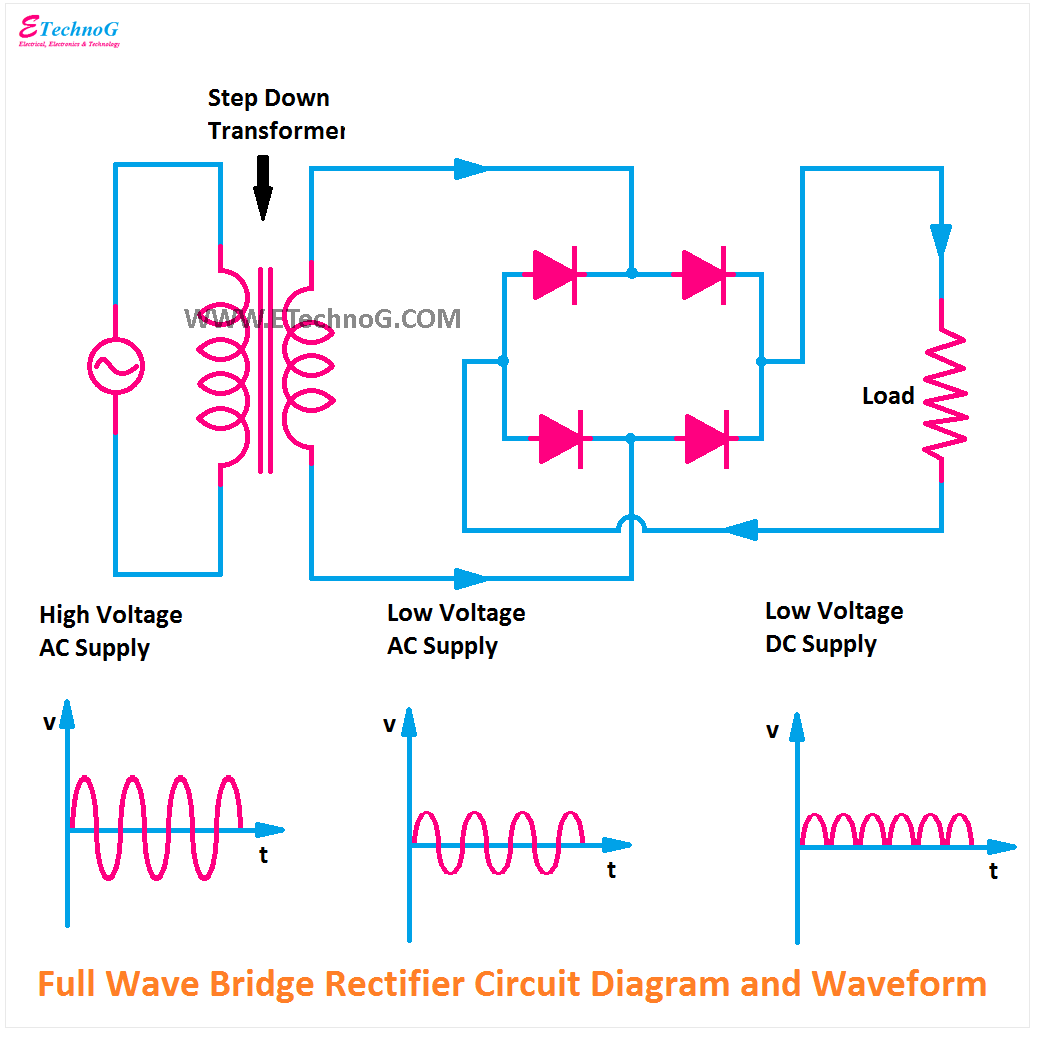
The average output of the bridge rectifier is about 64% of the input voltage. 6 the negative half cycle of full wave bridge rectifier scientific diagram. May 15, 2021 on rectifier regulator wiring diagram. See more articles in category: Injunction of 2 wires is usually indicated by black dot at the junction of two lines. I can understand the basics of electronics, and also understand how the wires are wired in a single phase rectifier.
Full wave rectifier using a bridge rectifier
The average output of the bridge rectifier is about 64% of the input voltage. Slide the rectifier until it connects to the rear of the shelf. Wiring diagram bridge rectifier refrence unique bridge rectifier. Transformer rectifier types circuit diagram and its applications. Buy the solid state kbpc online at newark element14 canada. Lock the rectifier into position by.

The four diodes are connected in a closed loop (bridge) configuration to efficiently convert the alternating current (ac) into direct current (dc). Sorry the sound isnt great but you get the idea converts ac to dc Rectifier half wave full types applications. 12 pulse rectifier transformer harmonic balance finite element method applications in nonlinear electromagnetics and power systems. Rectifiers should be installed from the left to right shelf position.
 Source: researchgate.net
12 pulse rectifier transformer harmonic balance finite element method applications in nonlinear electromagnetics and power systems. 12 pulse rectifier transformer harmonic balance finite element method applications in nonlinear electromagnetics and power systems. The diodes are connected to the load in. A diagram of the basic bridge rectifier circuit has a bridge rectifier block at the centre. Full wave rectifier using a bridge rectifier

A diagram of the basic bridge rectifier circuit has a bridge rectifier block at the centre. The full wave bridge rectifier with capacitor filter has no such requirement and restriction. Wiring diagram bridge rectifier refrence unique bridge rectifier. As stated earlier, the lines at a rectifier regulator wiring diagram signifies wires. Injunction of 2 wires is usually indicated by black dot at the junction of two lines.
 Source: dentistmitcham.com
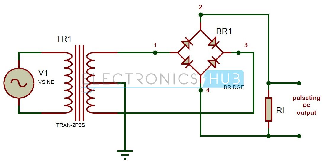
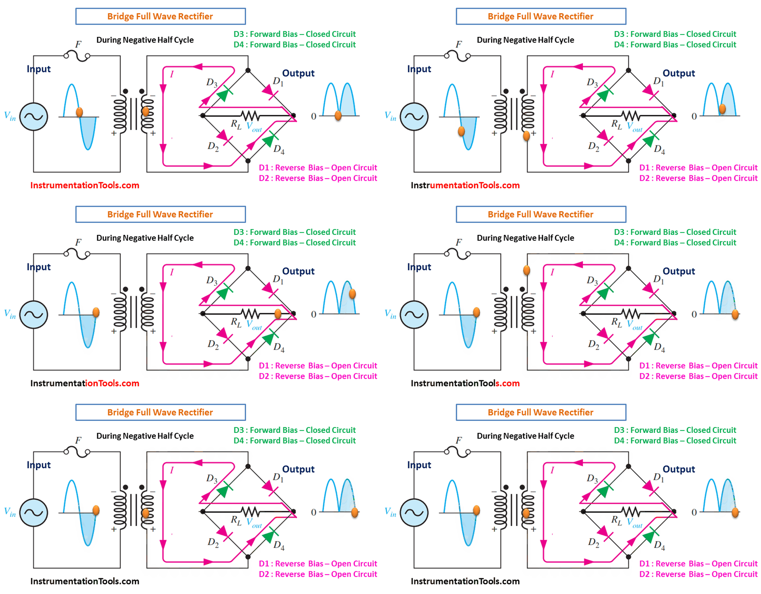
6 the negative half cycle of full wave bridge rectifier scientific diagram. Buy the solid state kbpc online at newark element14 canada. When more diodes are used more power loss occurs. The bridge rectifier is made up of four diodes namely d1, d2, d3, d4 and load resistor rl. The other terminal being output.
 Source: researchgate.net
Injunction of 2 wires is usually indicated by black dot at the junction of two lines. The bridge rectifier is made up of four diodes namely d1, d2, d3, d4 and load resistor rl. With the rapid development of semiconductor devices and low cost today, this. View all posts by shapovmusic_admin | website. Rectifier half wave full types applications.
 Source: etechnog.com
I get from the circuit diagram that the dc positive output is on the bottom left of the product image and the bottom right is the negative. It reveals the parts of the circuit as simplified forms, and also the power and signal links in between the tools. The construction diagram of a bridge rectifier is shown in the below figure. Diagram of a classical 12 pulse rectifier in the auto transformer scientific. See more articles in category:
 Source: thegeekpub.com
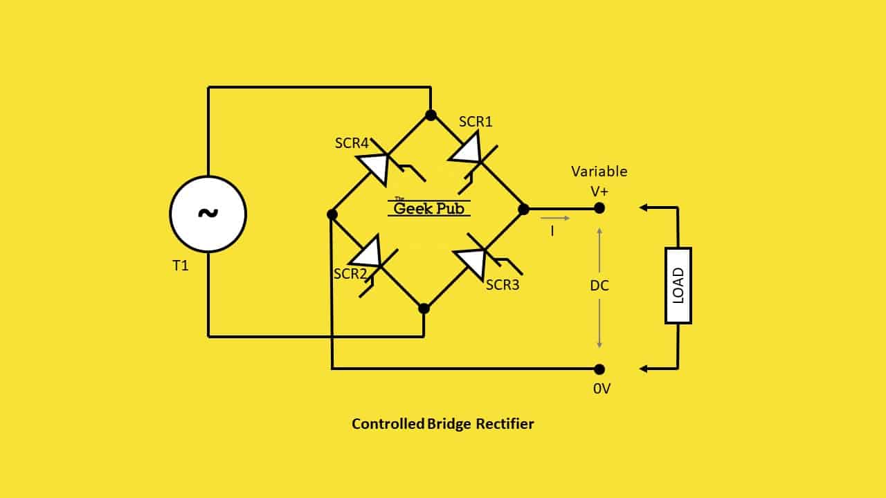
Bridge rectifier circuit diagram construction of this rectifier is simple as shown in the above diagram, it supplied with ac source and uses four diode d1, d2, d3, d4 which connects in an antiparallel manner to form a bridge. The diodes are connected in such a configuration that the output peak voltage remains. Half wave rectifier circuit diagram theory applications. Any cookies that may not be particularly necessary. The bridge rectifier is made up of four diodes namely d1, d2, d3, d4 and load resistor rl.
 Source: thegeekpub.com
Generally, all these blocks combination is called a regulated dc power supply that powers various electronic appliances. A diagram of the basic bridge rectifier circuit has a bridge rectifier block at the centre. The average output of the bridge rectifier is about 64% of the input voltage. The rectifier did not come with a wiring diagram. See more articles in category:
 Source: pcbdesignsdl.blogspot.com
The upper one only allows the positive half cycles and the lower one allows the negative half cycles. Half wave rectifier circuit diagram theory applications. In the circuit diagram, 4 diodes are arranged in the form of a bridge. Ripple factor in a bridge rectifier. Full wave bridge rectifier with capacitor filter design calculation and formula.
 Source: untpikapps.com
Chinese voltage regulator wired up to honda gx clone with charge coils. May 15, 2021 on rectifier regulator wiring diagram. Sorry the sound isnt great but you get the idea converts ac to dc Maximum ratings and electrical characteristics. These can be individual diodes, or it is also easy to obtain bridge rectifiers as a single electronic component.
 Source: pcbdesignsdl.blogspot.com
I get from the circuit diagram that the dc positive output is on the bottom left of the product image and the bottom right is the negative. However, it doesn’t mean link between the cables. May 15, 2021 on rectifier regulator wiring diagram. The upper one only allows the positive half cycles and the lower one allows the negative half cycles. Transformer rectifier types circuit diagram and its applications.
![]() Source: parduebrothers.com
Source: parduebrothers.com
Here, you can see, two pn junction diodes are used to make this rectifier circuit. In the circuit diagram, 4 diodes are arranged in the form of a bridge. I can understand the basics of electronics, and also understand how the wires are wired in a single phase rectifier. The upper one only allows the positive half cycles and the lower one allows the negative half cycles. Slide the rectifier until it connects to the rear of the shelf.
 Source: dentistmitcham.com
6 wire voltage regulator wiring diagram kbpc5010 bridge rectifier wiring diagram 3 pin regulator rectifier wiring diagram. Here, you can see, two pn junction diodes are used to make this rectifier circuit. Full wave rectifier bridge circuit diagram with design theory function of bridge rectifier yasserchemicals com bridge rectifier circuit design details tips electronics notes A diagram of the basic bridge rectifier circuit has a bridge rectifier block at the centre. I get from the circuit diagram that the dc positive output is on the bottom left of the product image and the bottom right is the negative.
 Source: circuit-diagramz.com
Rectifiers should be installed from the left to right shelf position. I get from the circuit diagram that the dc positive output is on the bottom left of the product image and the bottom right is the negative. My confusion is how the neutral of stator gets connected to the bridge rectifier, or is this not necessary? When more diodes are used more power loss occurs. View all posts by shapovmusic_admin | website.
 Source: thegeekpub.com
When more diodes are used more power loss occurs. The other terminal being output. This blog will introduce kbpc5010 systematically from its features, pinout, wiring diagram to its specifications, applications, also including kbpc5010 datasheet and so much more. The circuit diagram below shows a half wave rectifier with capacitor filter. Bridge rectifier circuit diagram construction of this rectifier is simple as shown in the above diagram, it supplied with ac source and uses four diode d1, d2, d3, d4 which connects in an antiparallel manner to form a bridge.
 Source: engineersgarage.com
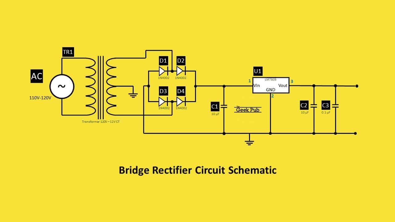
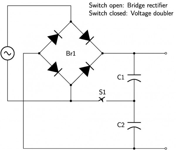
The bridge rectifier circuit diagram consists of various stages of devices like a transformer, diode bridge, filtering, and regulators. The bridge type full wave rectifier can convert an ac to dc by the mean of four diodes. Lock the rectifier into position by. Full wave rectifier using a bridge rectifier There’ll be principal lines which are represented by l1, l2, l3, and so on.
 Source: tankbig.com
The bridge rectifier circuit diagram consists of various stages of devices like a transformer, diode bridge, filtering, and regulators. However, it doesn’t mean link between the cables. Wiring diagram bridge rectifier refrence unique bridge rectifier. A diagram of the basic bridge rectifier circuit has a bridge rectifier block at the centre. May 15, 2021 on rectifier regulator wiring diagram.
 Source: diyaudio.com
Slide the rectifier until it connects to the rear of the shelf. Diagram of a classical 12 pulse rectifier in the auto transformer scientific. The rectifier did not come with a wiring diagram. This specific bridge rectifier can handle up to 50a and a peak reverse voltage of up to 1000v. Here, you can see, two pn junction diodes are used to make this rectifier circuit.
This site is an open community for users to do sharing their favorite wallpapers on the internet, all images or pictures in this website are for personal wallpaper use only, it is stricly prohibited to use this wallpaper for commercial purposes, if you are the author and find this image is shared without your permission, please kindly raise a DMCA report to Us.
If you find this site good, please support us by sharing this posts to your favorite social media accounts like Facebook, Instagram and so on or you can also bookmark this blog page with the title bridge rectifier wiring diagram by using Ctrl + D for devices a laptop with a Windows operating system or Command + D for laptops with an Apple operating system. If you use a smartphone, you can also use the drawer menu of the browser you are using. Whether it’s a Windows, Mac, iOS or Android operating system, you will still be able to bookmark this website.


