Your Cnc control box wiring diagram images are available in this site. Cnc control box wiring diagram are a topic that is being searched for and liked by netizens now. You can Find and Download the Cnc control box wiring diagram files here. Get all free photos.
If you’re looking for cnc control box wiring diagram images information connected with to the cnc control box wiring diagram keyword, you have come to the ideal blog. Our website frequently provides you with suggestions for seeking the maximum quality video and picture content, please kindly surf and find more informative video content and images that fit your interests.
Cnc Control Box Wiring Diagram. 11th april 2016, 01:26 pm #5. Arduino uno with grbl pin connection scientific diagram. I�m a bit of a dummy, when it comes to electronics and wiring, so this looks good. Wiring instructions of extended manual control box
 17 Wiring Relay Module To CNC Controller 17 / CNC From youtube.com
Wiring home and limit switches. Cnc4you ltd assumes our equipment will be integrated into industrial control equipment and as above integrated safely to avoid injury to yourselves or third. Dc wire then 1.25mm/2 (awg 16) for higher loads ie: Thanks kryn to grow old is mandatory, growing up is optional. Make sure the control box and vfd are off before proceeding. Wiring instructions of extended manual control box
Are you able to draw the wiring diagram if it�s able to do so please?
Wading through all the wire available is a monumental task of its own, but for the purposes of this article it is only necessary to consider the types of wires typically used when wiring a cnc controller. If in doubt, have your electrician refer to the wiring diagram included in the control box door. Camtool v3 3 optical limit switches cnc 3018 pro issue 645 gnea grbl github. Each ih switch contains 2 optical switches and can sense a limit in either direction. Or, use a 4 core wire to the control box and individual wires within. Below is the manufacturer’s suggested installation procedure.
![[XM_8232] Cnc Control Box Wiring Diagram Schematic Wiring](https://static-assets.imageservice.cloud/529886/acorn-cnc-controller-step-and-direction-4-axis-cnc-control-board.png "[XM_8232] Cnc Control Box Wiring Diagram Schematic Wiring") Source: benkeme.umng.itive.kumb.sequ.phae.mohammedshrine.org
Source: benkeme.umng.itive.kumb.sequ.phae.mohammedshrine.org
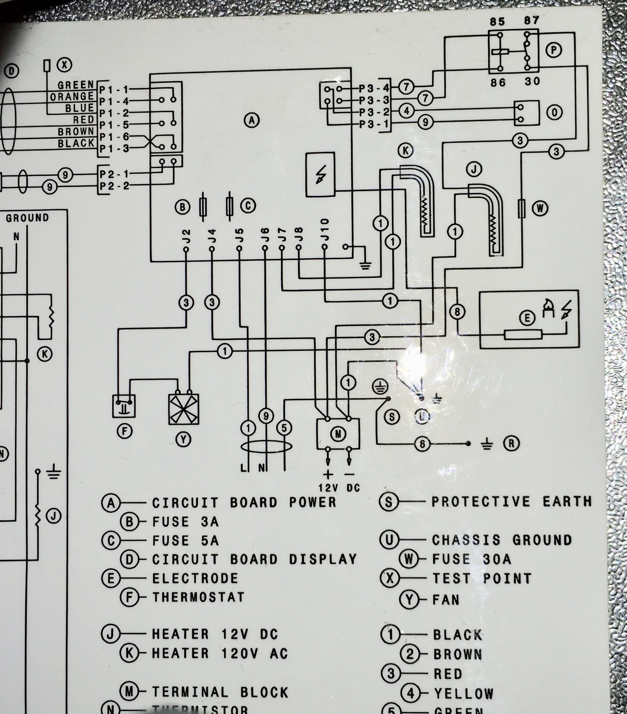
Can/will the cnc control box accept a 4th axis? Tormach offers a passive cnc touch probe for its pcnc milling machines, which is ideal for defining work offsets on a mill. Wiring a dg3s driver using a c34gd. L/n and ground wires are connected to wire terminal blocks which are mounted in the cnc control box. Nema 23 3 axis control.
![[XM_8232] Cnc Control Box Wiring Diagram Schematic Wiring](https://static-cdn.imageservice.cloud/2272717/wiring-cnc-control-box-carbonvotemuditblog.jpg "[XM_8232] Cnc Control Box Wiring Diagram Schematic Wiring") Source: benkeme.umng.itive.kumb.sequ.phae.mohammedshrine.org
Source: benkeme.umng.itive.kumb.sequ.phae.mohammedshrine.org
Can/will the cnc control box accept a 4th axis? Are you able to draw the wiring diagram if it�s able to do so please? Front panel connects signal wire, another end of signal wire connects control panel interface on the computer. Or, use a 4 core wire to the control box and individual wires within. The wiring of the parallel breakout board from the output terminals to the driver digital pulse (step pulse) and direction lines are explained.
![[BG_0852] Cnc Control Box Wiring Diagram Free Diagram](https://static-cdn.imageservice.cloud/529820/cnc-machine-wiring-diagram-wiring-diagram-tutorial.jpg "[BG_0852] Cnc Control Box Wiring Diagram Free Diagram") Source: benkeme.umng.itive.kumb.sequ.phae.mohammedshrine.org
Source: benkeme.umng.itive.kumb.sequ.phae.mohammedshrine.org
Make sure the control box and vfd are off before proceeding. On the electrical control box, it prints the marks of the ports. Altivar 61 control wiring diagram stepper motors divide a full rotation into hundreds of discrete steps which makes them ideal to precisely control movements be it in cars robots 3d printers or cnc machines most stepper while early efi systems had their failings the technology brought with it a new standard of reliability and control expect. Front panel connects signal wire, another end of signal wire connects control panel interface on the computer. Wiring guide for rev 2.
 Source: get-gets.blogspot.com
L/n and ground wires are connected to wire terminal blocks which are mounted in the cnc control box. Thanks kryn to grow old is mandatory, growing up is optional. The new parallel breakout board appears a bit different, but the process of wiring and testing is the same. The wiring is simple but there is no indication if one of the switches is the schematic of the end sensor board which uses optocouplers. 11th april 2016, 01:26 pm #5.
![[DIAGRAM] Cnc Control Box Wiring Diagram FULL Version HD](https://schematron.org/image/lofrans-control-box-wiring-diagram-8.jpg "[DIAGRAM] Cnc Control Box Wiring Diagram FULL Version HD") Source: sacwiringh.loomloom.it
Source: sacwiringh.loomloom.it
This kit contains the following matched parts for your cnc project. Cnc cutting machine user�s manual contents functional overview main menu auto man edit command system setup libminit diagnose i/o interface appendix 1. If in doubt, have your electrician refer to the wiring diagram included in the control box door. Are you able to draw the wiring diagram if it�s able to do so please? Make sure the control box and vfd are off before proceeding.
 Source: campo-alegre.blogspot.com
A torch on/off cable and a thc port wiring cable. The electronics combos come with stepping motor drivers, stepping motors, breakout board (interface between the computer and the drivers) and power supply. 102xx) have an alternate wiring setup. All cables and wires are routed inside and out of the control box. On the electrical control box, it prints the marks of the ports.
![[BG_0852] Cnc Control Box Wiring Diagram Free Diagram](https://static-assets.imageservice.cloud/2272714/mini-cnc-controller-wiring-diagram-wiring-library.jpg "[BG_0852] Cnc Control Box Wiring Diagram Free Diagram") Source: benkeme.umng.itive.kumb.sequ.phae.mohammedshrine.org
Source: benkeme.umng.itive.kumb.sequ.phae.mohammedshrine.org
All cables and wires are routed inside and out of the control box. I�m a bit of a dummy, when it comes to electronics and wiring, so this looks good. Here are some of the components i�ve used to build cnc control boxes. I am putting together my first cnc, but need help with the wiring for the control box for the vfd to make sure it will work and i don�t blow my self up. Introduction of wiring of cnc router rear ends of control box of cnc router connect with x and y (two pieces), z, frequency converter, limit switch and external power source (ac 220v) separately.
 Source: maher-ramblings.blogspot.com
The wiring of the parallel breakout board from the output terminals to the driver digital pulse (step pulse) and direction lines are explained. Nema 23 3 axis control. Cnc stepper motor control box. Ac wire needs to be 2.5mm/2 flex wire cable not ridged stuff like in walls. Camtool v3 3 optical limit switches cnc 3018 pro issue 645 gnea grbl github.
![[BG_0852] Cnc Control Box Wiring Diagram Free Diagram](https://static-cdn.imageservice.cloud/2272724/mach3-control-panel-wiring-wiring-diagram-data-schema.jpg "[BG_0852] Cnc Control Box Wiring Diagram Free Diagram") Source: benkeme.umng.itive.kumb.sequ.phae.mohammedshrine.org
Source: benkeme.umng.itive.kumb.sequ.phae.mohammedshrine.org
Adding axis limit and emergency stop switches to a sainsmart 3018 pro cnc machine resource center. Cnc shield 2 stepper motors how to setup grbl control machine arduino uno with a4988 tb6560 plus v3 0 usb project manual lcd controller clone one axis on the for motor driver tb6600 nema23 6 robotics pin connection set up and get using mega as diy plotter kit printer dengan papan rancang ban. Discussion starter · #1 · feb 9, 2021. Or, use a 4 core wire to the control box and individual wires within. I�m a bit of a dummy, when it comes to electronics and wiring, so this looks good.
 Source: youtube.com
I am going to be running nema 23�s 425oz drawing 3amps. Introduction to cnc for a total novice setting up laser sainsmart resource center 3018 pro engraver review and setup tutorial upgrade version 2 in 1 3000mw grbl control diy mini machine 3 axis wood router with offline controller bits er11 extension ro online taiwan b07hnwt572 engraving gf3018 紐軒cnc3018 2418 1610鐳射數控雕刻機控制板grbl控制板ttl. Each ih switch contains 2 optical switches and can sense a limit in either direction. Here are some of the components i�ve used to build cnc control boxes. Are you able to draw the wiring diagram if it�s able to do so please?
![[BG_0852] Cnc Control Box Wiring Diagram Free Diagram](https://static-assets.imageservice.cloud/2272735/cnc-router-for-diy-pcb-manufacturing-pocketmagic.jpg "[BG_0852] Cnc Control Box Wiring Diagram Free Diagram") Source: benkeme.umng.itive.kumb.sequ.phae.mohammedshrine.org
Source: benkeme.umng.itive.kumb.sequ.phae.mohammedshrine.org
Cnc cutting machine user�s manual contents functional overview main menu auto man edit command system setup libminit diagnose i/o interface appendix 1. Arduino uno with grbl pin connection scientific diagram. This unit is suitable for our nema23 stepper motors from 1.5nm to our 4.5nm or your own steppers please check for compatibility if in doubt as no steppers are supplied with this unit please see other controller�s as full kits. Outputs on the grbl board in the following diagram. 0.5mm/2 (awg 20) for smaller loads relays etc.
 Source: pinterest.com.au
This instructable is in 3 parts: The wiring of the parallel breakout board from the output terminals to the driver digital pulse (step pulse) and direction lines are explained. Operation of your cnc or automated machinery. Tormach offers a passive cnc touch probe for its pcnc milling machines, which is ideal for defining work offsets on a mill. I�m a bit of a dummy, when it comes to electronics and wiring, so this looks good.
 Source: tradecraftspecialties.com
Wiring a dg3s driver using a c34gd. Need a cnc control panel layed out for a cnc mill i would like a wiring diagram and a parts list along with a cad drawing showing the layout. This instructable is in 3 parts: Below is the manufacturer’s suggested installation procedure. Eletric wiring diagram scientific cnc 014 ocean controls electrical of the 3 axis milling machine emco compact 5 pdf doent plasma cutting block connect hardware for board rev2 x mechmate 25feb txt xy plotter.
 Source: schematron.org
Autocad, cad/cam, mechanical engineering, product design, solidworks Wiring a dg3s driver using a c27. I am going to be running nema 23�s 425oz drawing 3amps. Two cnc cables are also provided in the plasma cutter box; Autocad, cad/cam, mechanical engineering, product design, solidworks
 Source: ebay.com
Autocad, cad/cam, mechanical engineering, product design, solidworks On the electrical control box, it prints the marks of the ports. Cnc cutting machine user�s manual contents functional overview main menu auto man edit command system setup libminit diagnose i/o interface appendix 1. Dc wire then 1.25mm/2 (awg 16) for higher loads ie: Wiring instructions of extended manual control box
![[YT_6044] Cnc Control Box Wiring Diagram Free Diagram](https://static-cdn.imageservice.cloud/2272718/upgrading-a-cnc-milling-machine-part-1.jpg "[YT_6044] Cnc Control Box Wiring Diagram Free Diagram") Source: benkeme.umng.itive.kumb.sequ.phae.mohammedshrine.org
Source: benkeme.umng.itive.kumb.sequ.phae.mohammedshrine.org
I�m a bit of a dummy, when it comes to electronics and wiring, so this looks good. Go to the new parallel breakout board to get more information and the wiring diagram. This instructable is in 3 parts: Additionally, how the wire is to be used can have some effect on the overall system. Are you able to draw the wiring diagram if it�s able to do so please?
Source: youtube.com
However, i am undecided as to whether to use individual wires so i can match up the motor colours all the way through to the drivers. Two cnc cables are also provided in the plasma cutter box; I am putting together my first cnc, but need help with the wiring for the control box for the vfd to make sure it will work and i don�t blow my self up. Camtool v3 3 optical limit switches cnc 3018 pro issue 645 gnea grbl github. This unit is suitable for our nema23 stepper motors from 1.5nm to our 4.5nm or your own steppers please check for compatibility if in doubt as no steppers are supplied with this unit please see other controller�s as full kits.
 Source: cnccookbook.com
Cnc stepper motor control box. The wiring is simple but there is no indication if one of the switches is the schematic of the end sensor board which uses optocouplers. Cnc stepper motor control box. Make sure the control box and vfd are off before proceeding. I am putting together my first cnc, but need help with the wiring for the control box for the vfd to make sure it will work and i don�t blow my self up.
This site is an open community for users to do submittion their favorite wallpapers on the internet, all images or pictures in this website are for personal wallpaper use only, it is stricly prohibited to use this wallpaper for commercial purposes, if you are the author and find this image is shared without your permission, please kindly raise a DMCA report to Us.
If you find this site beneficial, please support us by sharing this posts to your preference social media accounts like Facebook, Instagram and so on or you can also bookmark this blog page with the title cnc control box wiring diagram by using Ctrl + D for devices a laptop with a Windows operating system or Command + D for laptops with an Apple operating system. If you use a smartphone, you can also use the drawer menu of the browser you are using. Whether it’s a Windows, Mac, iOS or Android operating system, you will still be able to bookmark this website.