Your Arc fault receptacle wiring diagram images are available in this site. Arc fault receptacle wiring diagram are a topic that is being searched for and liked by netizens today. You can Download the Arc fault receptacle wiring diagram files here. Get all royalty-free photos.
If you’re searching for arc fault receptacle wiring diagram pictures information related to the arc fault receptacle wiring diagram topic, you have come to the right blog. Our website frequently provides you with hints for viewing the maximum quality video and image content, please kindly surf and find more enlightening video articles and graphics that fit your interests.
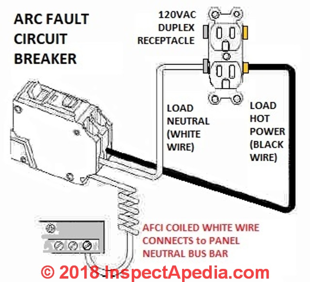
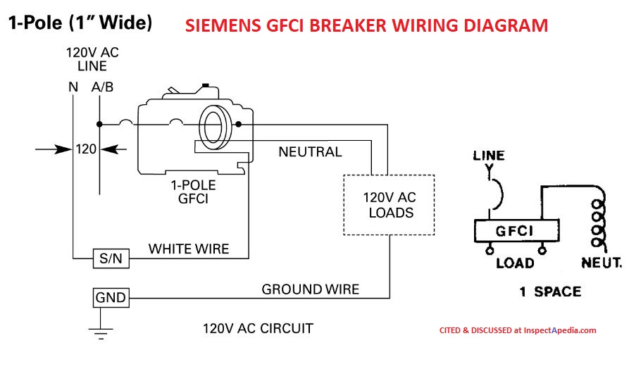
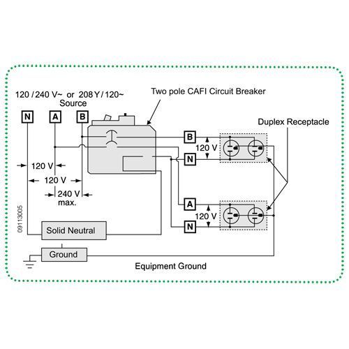
Arc Fault Receptacle Wiring Diagram. Depending on the location of the receptacle being installed or replaced, it may need to be protected with arc fault or ground fault circuit interruption. How to wire a gfci breaker the river pool is rooted in italian wiring square d 50 amp electrical requirements two men and homeline 30 2 pole 20 1 dual single circuit at arc fault interrupter afci. Many individuals believe that gfci (ground fault circuit interrupter), in either the receptacle (figure 1) or breaker (figure 2) style cannot be used on a 2 wire circuit. Turn off the power at the main circuit panel and remove the old outlet.
 Arc Fault Breaker Wiring Diagram Free Wiring Diagram From ricardolevinsmorales.com
You can also learn about wiring gfci outlets in. To switch the recepticle, remove the jumper link, and wire according to diagram. Afci wiring room wiring diagram 500. Wiring diagrams for electrical receptacle outlets. Where a recepta cle outlet is located in any areas specified in 210.12(a) or (b), a replacement receptacle at this outlet shall be one of the following: The term afci is an acronym that stands for arc fault circuit interrupter and is applied to a certain type of circuit breaker or outlet receptacle that aims at preventing sparking or arcing that can potentially cause an.
Arc fault wiring diagram wiring diagram.
Wiring for a switch and gfci receptacle in the same box is also shown. Ground fault breaker wiring diagram. Since one main purpose of afci circuits is to detect arc faults in the in wall wiring (such as from hammering a nail into the wiring) as well as devices plugged into the wiring, the placement at the breaker is crucial. Arcing creates high intensity heating at the point of the arc, resulting in burning particles that can exceed 10,000 degrees fahrenheit and may over time ignite surrounding material such as wood framing or insulation. • understand basic wiring principles and techniques • can interpret wiring diagrams • have circuit wiring experience The load must be connected to the load terminals.
 Source: pinterest.com
To properly wire gfci, or ground fault circuit interrupter receptacles, turn off the power to the circuit you’re working on and unscrew the cover plate on the outlet box. This diagram illustrates the wiring for a circuit with 2 gfci receptacles followed by a light and switch. Ground fault protection systems performance testing basics. In our previous posts we have learned different types of afci wiring diagrams such. In this four wire afci wiring diagram, two lines as l 1 and l 2 has been connected to the input terminals of afci breaker and the builtin white is connected to the neutral busbar in the mains supply.

Since one main purpose of afci circuits is to detect arc faults in the in wall wiring (such as from hammering a nail into the wiring) as well as devices plugged into the wiring, the placement at the breaker is crucial. In this four wire afci wiring diagram two lines as l 1 and l 2 has been connected to the input terminals of afci breaker and the builtin white is connected to the neutral busbar in the mains supply. Arc fault breaker wiring diagram wiring diagram. Here is a picture gallery about ground fault circuit interrupter wiring diagram complete with the description of the image please find. Search for wiring diagrams ground fault wiring here and subscribe to this site wiring diagrams ground fault wiring read more!
 Source: tonetastic.info
In this four wire afci wiring diagram, two lines as l 1 and l 2 has been connected to the input terminals of afci breaker and the builtin white is connected to the neutral busbar in the mains supply. You can also learn about wiring gfci outlets in. The three load terminals of afci breaker is directly connected to the electric stove control box panel following the sequence as line 1 (red), neutral (black in the middle) and line 2 (blue). How to wire for both ground fault arc fault protection youtube from i.ytimg.com. To properly wire gfci, or ground fault circuit interrupter receptacles, turn off the power to the circuit you’re working on and unscrew the cover plate on the outlet box.
 Source: kelvin-okl.blogspot.com
Many individuals believe that gfci (ground fault circuit interrupter), in either the receptacle (figure 1) or breaker (figure 2) style cannot be used on a 2 wire circuit. Installing an outlet branch circuit afci receptacle can be more complicated than installing a conventional receptacle. 220 vokt ground fault breaker. Single pole switches can control just one circuit and a double pole switch can control two circuits. The 8 most common national electric code violations diyers.

How to wire for both ground fault arc fault protection youtube from i.ytimg.com. You can also learn about wiring gfci outlets in. Legrand radiant 15 amp dual function self test tamper. Turn off the power at the main circuit panel and remove the old outlet. Wiring for a switch and gfci receptacle in the same box is also shown.
 Source: texags.com
Single pole switches can control just one circuit and a double pole switch can control two circuits. Many individuals believe that gfci (ground fault circuit interrupter), in either the receptacle (figure 1) or breaker (figure 2) style cannot be used on a 2 wire circuit. Since one main purpose of afci circuits is to detect arc faults in the in wall wiring (such as from hammering a nail into the wiring) as well as devices plugged into the wiring, the placement at the breaker is crucial. Arc fault breaker wiring diagram wiring diagram. Depending on the location of the receptacle being installed or replaced, it may need to be protected with arc fault or ground fault circuit interruption.
 Source: rebablakuf.blogspot.com
Afci wiring room wiring diagram 500. Arc fault circuit interrupters afcis replace an electrical outlet. The three load terminals of afci breaker is directly connected to the electric stove control box panel following the sequence as line 1 (red), neutral (black in the middle) and line 2 (blue). The term afci is an acronym that stands for arc fault circuit interrupter and is applied to a certain type of circuit breaker or outlet receptacle that aims at preventing sparking or arcing that can potentially cause an. In this basic wiring diagram, a standard outlet has been connected to the gfci load terminals while the gfci has been connected to the load terminals of afci.
 Source: diychatroom.com
Wiring diagrams for electrical receptacle outlets. Many individuals believe that gfci (ground fault circuit interrupter), in either the receptacle (figure 1) or breaker (figure 2) style cannot be used on a 2 wire circuit. Installing an outlet branch circuit afci receptacle can be more complicated than installing a conventional receptacle. Arc fault breaker wiring diagram wiring diagram. Eaton combination switch wiring diagram.
 Source: kelvin-okl.blogspot.com
Essential tips for safe electrical repairs Installing an outlet branch circuit afci receptacle can be more complicated than installing a conventional receptacle. To switch the recepticle, remove the jumper link, and wire according to diagram. Seek professional advice for the receptacle location. Turn off the power at the main circuit panel and remove the old outlet.
 Source: ricardolevinsmorales.com
Wall outlet wiring wiring diagram. Turn off the power at the main circuit panel and remove the old outlet. Single pole switches can control just one circuit and a double pole switch can control two circuits. 2) attach the ground pigtail to the green ground screw, then insert the neutral pigtail into a neutral “line” terminal hole on the back of the device. Wiring gfci outlets in series.
 Source: kelvin-okl.blogspot.com
Connect the bare ground wire to the green ground screw. Since one main purpose of afci circuits is to detect arc faults in the in wall wiring (such as from hammering a nail into the wiring) as well as devices plugged into the wiring, the placement at the breaker is crucial. The three load terminals of afci breaker is directly connected to the electric stove control box panel following the sequence as line 1 (red), neutral (black in the middle) and line 2 (blue). Here is a picture gallery about ground fault circuit interrupter wiring diagram complete with the description of the image please find. Many individuals believe that gfci (ground fault circuit interrupter), in either the receptacle (figure 1) or breaker (figure 2) style cannot be used on a 2 wire circuit.

Eaton combination switch wiring diagram. The term afci is an acronym that stands for arc fault circuit interrupter and is applied to a certain type of circuit breaker or outlet receptacle that aims at preventing sparking or arcing that can potentially cause an. Many individuals believe that gfci (ground fault circuit interrupter), in either the receptacle (figure 1) or breaker (figure 2) style cannot be used on a 2 wire circuit. Where a recepta cle outlet is located in any areas specified in 210.12(a) or (b), a replacement receptacle at this outlet shall be one of the following: Wiring diagram consists of numerous in depth illustrations that show the connection of assorted things.
 Source: kelvin-okl.blogspot.com
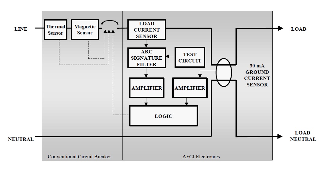
An arc fault circuit interrupter (afci) is a circuit protection device designed to protect against fires caused by arcing faults in electrical wiring. Shunt trip circuit breaker wiring diagram. Wiring diagrams for gfci outlets. Td03309004e for more information visit. This diagram illustrates the wiring for a circuit with 2 gfci receptacles followed by a light and switch.
 Source: kelvin-okl.blogspot.com
In our previous posts we have learned different types of afci wiring diagrams such. Wiring diagrams for electrical receptacle outlets. This diagram illustrates wiring a gfci receptacle and light switch in the same outlet box a common arrangement in a bathroom with limited space. Event of an arc fault. Residential electrical afci wiring diagrams.
![[GK_2392] Afci Outlet Wiring Diagram Wiring Diagram [GK_2392] Afci Outlet Wiring Diagram Wiring Diagram](https://static-assets.imageservice.cloud/397672/wiring-multiple-gfci-schematics-wiring-diagram-tutorial.jpg) Source: cular.phon.renstra.fr09.org
Source: cular.phon.renstra.fr09.org
Wall outlet wiring wiring diagram. Arc fault wiring diagram wiring diagram. Td03309004e for more information visit. Installing an outlet branch circuit afci receptacle can be more complicated than installing a conventional receptacle. Wiring for a switch and gfci receptacle in the same box is also shown.
 Source: afcisafetyreceptacles.org
To properly wire gfci, or ground fault circuit interrupter receptacles, turn off the power to the circuit you’re working on and unscrew the cover plate on the outlet box. Wall outlet wiring wiring diagram. Essential tips for safe electrical repairs This way, the standard outlet receptacle is protected by both afci and gfci. 15a, 125v/ac 20a, 125v/ac design features • protects against arc faults in wiring resulting from damaged insulation and other causes that can lead to electrical fires • outlet branch circuit (obc) afci receptacles protect from series and.

Shunt trip circuit breaker wiring diagram. It works by comparing the input current on the ungrounded side red wire to the output current on the neutral side black wire. Single pole switches can control just one circuit and a double pole switch can control two circuits. Many individuals believe that gfci (ground fault circuit interrupter), in either the receptacle (figure 1) or breaker (figure 2) style cannot be used on a 2 wire circuit. Shunt trip circuit breaker wiring diagram.
 Source: amateurradio.com
Legrand radiant 15 amp dual function self test tamper. Installing an outlet branch circuit afci receptacle can be more complicated than installing a conventional receptacle. Where a recepta cle outlet is located in any areas specified in 210.12(a) or (b), a replacement receptacle at this outlet shall be one of the following: Wiring diagrams for electrical receptacle outlets. You can also learn about wiring gfci outlets in.
This site is an open community for users to share their favorite wallpapers on the internet, all images or pictures in this website are for personal wallpaper use only, it is stricly prohibited to use this wallpaper for commercial purposes, if you are the author and find this image is shared without your permission, please kindly raise a DMCA report to Us.
If you find this site beneficial, please support us by sharing this posts to your own social media accounts like Facebook, Instagram and so on or you can also bookmark this blog page with the title arc fault receptacle wiring diagram by using Ctrl + D for devices a laptop with a Windows operating system or Command + D for laptops with an Apple operating system. If you use a smartphone, you can also use the drawer menu of the browser you are using. Whether it’s a Windows, Mac, iOS or Android operating system, you will still be able to bookmark this website.

