Your 4 wire bipolar stepper motor wiring diagram images are ready in this website. 4 wire bipolar stepper motor wiring diagram are a topic that is being searched for and liked by netizens today. You can Get the 4 wire bipolar stepper motor wiring diagram files here. Find and Download all royalty-free photos and vectors.
If you’re looking for 4 wire bipolar stepper motor wiring diagram pictures information linked to the 4 wire bipolar stepper motor wiring diagram topic, you have visit the ideal blog. Our website frequently gives you hints for downloading the highest quality video and image content, please kindly surf and find more enlightening video articles and graphics that fit your interests.
4 Wire Bipolar Stepper Motor Wiring Diagram. 6 wire stepper motor wiring diagram. The following diagram shows the connections to be made for an 8 wire series connected bipolar stepper motor. 4 wire stepper motor driver circuit diagram wiring diagram line wiring diagram. 4 wire stepper motor driver circuit diagram wiring diagram line wiring diagram.
 4 Wire Stepper Motor Wiring Diagram Collection From dentistmitcham.com
Of 4, 5, 6, and 8 wires, which can be unipolar or bipolar. Connecting this motor type is very straightforward and simply requires connecting the a and a� leads to the corresponding phase outputs on your motor drive. 4 wire bipolar stepper motor driver schematic wiring diagram line wiring diagram wiring diagram line we are make source the schematics, wiring diagrams and technical photos Since coils a and b on the diagram above are not connected, the resistance between leads a1 and b1, or between a1 and b2 will be infinite. The first element is symbol that indicate electrical element from the circuit. Connecting a stepper motor to a buildbotics cnc controller requires properly connecting the four wires from the driver to the right wires on the motor.
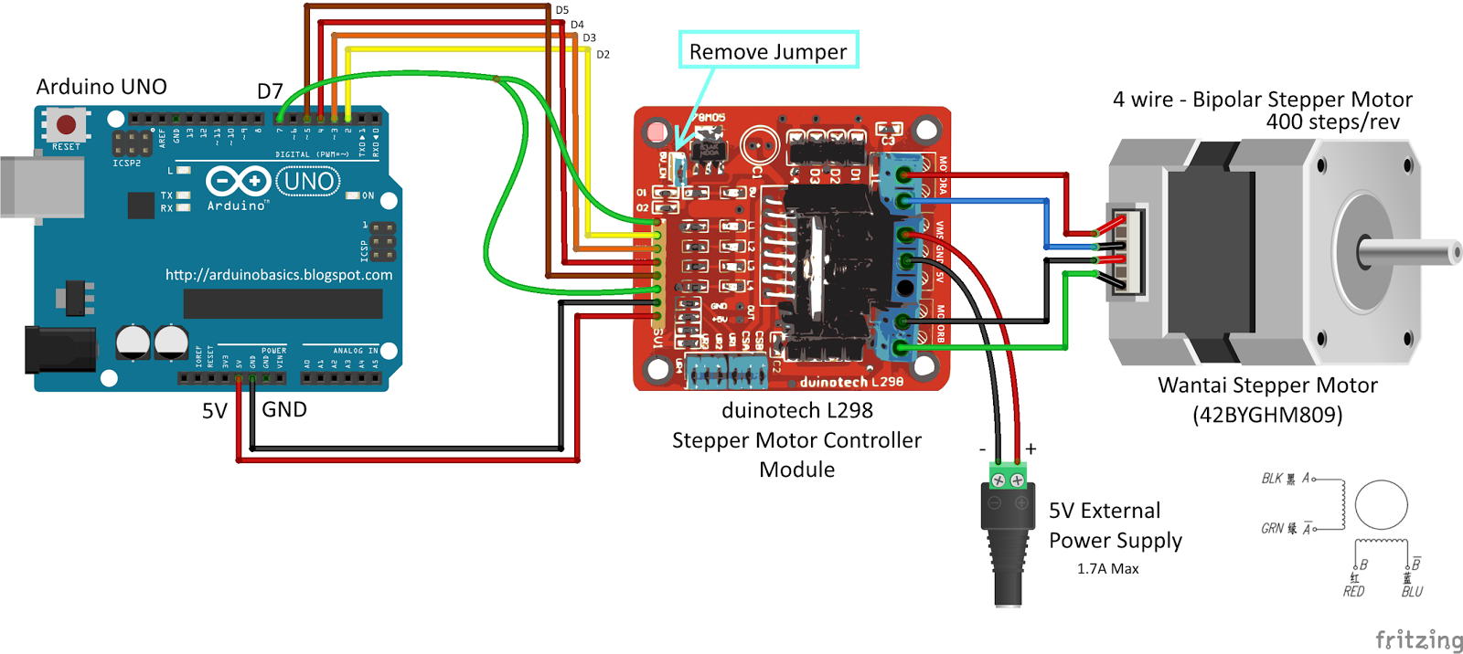
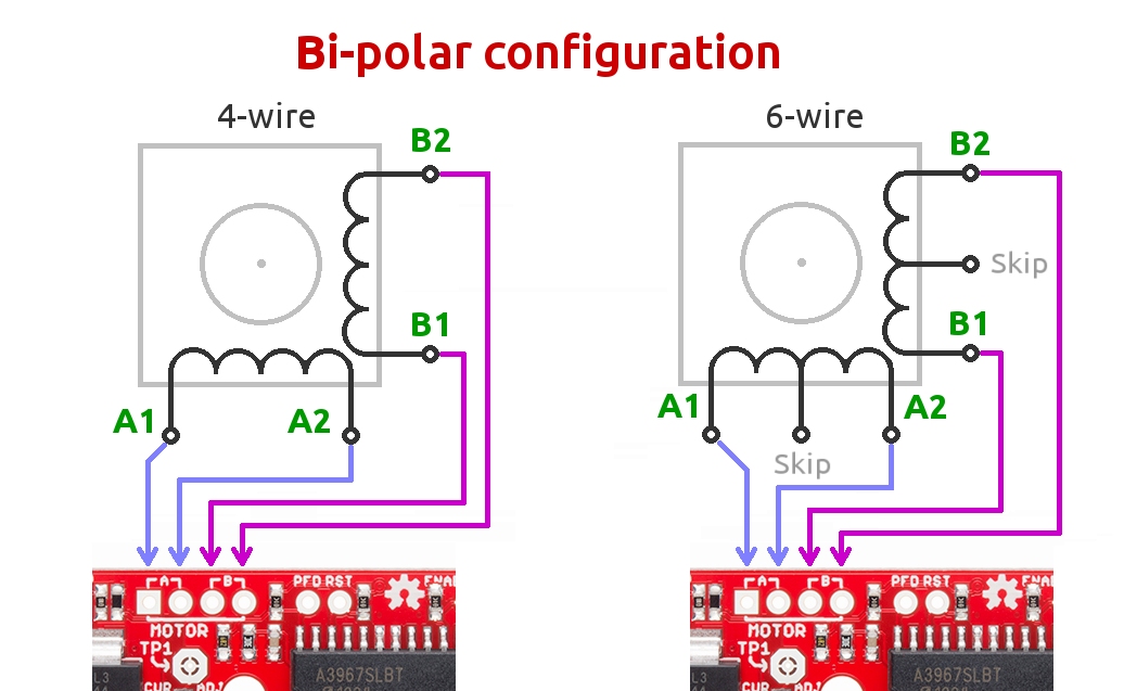
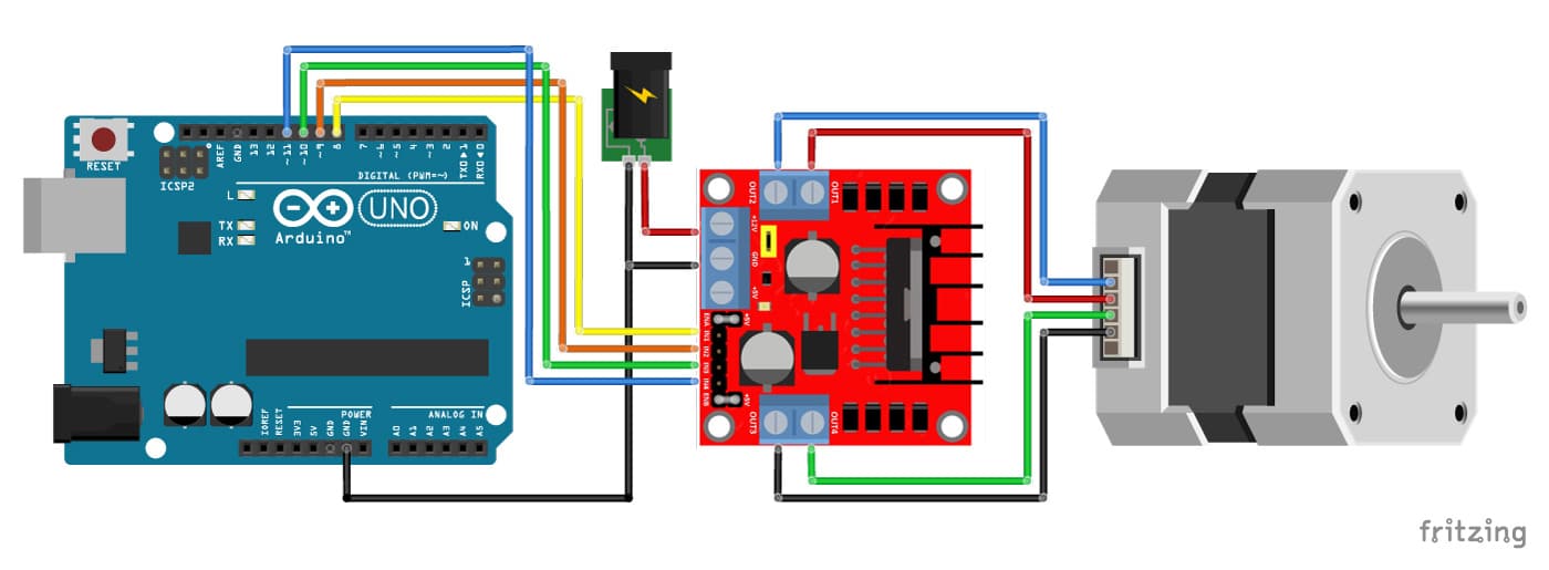
For example, if using the above 4 wire motor with color code 1, the red wire would be connected to a, blue connected to a, green connected to b, and black connected to b.
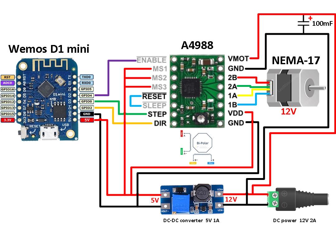
Each phase nema 17 dimensions wiring diagram. The only thing you need to identify is the two pairs of wires which are connected to each of the two coils. This is a common word during discussions involving peculiarities of step motors which can have 4 5 6 and 8 wires. Unfortunately, stepper motors come in a variety of configurations and it is not always immediately obvious how to hook them up. Since i do not have a driver at hand, i need to convert the circuit so it works with 4 transistors instead. Stepper motor with l298n and arduino tutorial 4 examples 555 timer controller circuit a4988 driver how to wire motors bipolar control simple projects what is it sequence electrical4u.
 Source: wiringschemas.blogspot.com
One coil gets connected to out1 and out2 and the. If your stepper motor has 4 wires, it is a bipolar stepper motor. The 4 wires, 5 wires and 6 wires stepper motors). The trick is figuring out which wires make up the coil pairs. 6 wire stepper motor wiring diagram.
 Source: wiringschemas.blogspot.com
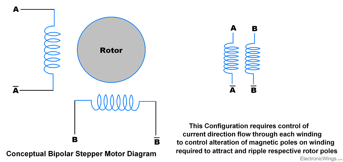
If you have a unipolar drive, the terminal will be labeled a, b, c, d and a/c common, b/d common (or comm) notes: Account suspended stepper motor printer 3d printer. On arduino website, the sample circuit�s stepper has 4 wires and is directly connected to a driver ic (a lmxxx), and the driver is connected to arduino. Bipolar stepper motors have two windings, which are not connected to each other, wired internally like this: The trick is figuring out which wires make up the coil pairs.
 Source: schematron.org
If your stepper motor has 4 wires it is a bipolar stepper motor. Learning to control a stepper motor with the arduino motor shield. There are several characteristics that make stepper motors different from one. For instance , if a module is usually powered up and it sends out a new signal of half the voltage and the technician will not know this, he would think he has a challenge, as he would. The 4 wires, 5 wires and 6 wires stepper motors).
 Source: dentistmitcham.com
Rb_1509 5 wire fan motor diagram. There are slight differences on how the different variant of stepper motors work (i.e. Connecting this motor type is very straightforward and simply requires connecting the a and a� leads to the corresponding phase outputs on your motor drive. For instance , if a module is usually powered up and it sends out a new signal of half the voltage and the technician will not know this, he would think he has a challenge, as he would. So do check out my other instructable videos on these motors to learn more.
 Source: schematron.org
Lin engineering step motors are available with either 2 coil bipolar or 4 coil unipolar windings. The first element is symbol that indicate electrical element from the circuit. Vm_8397 fan motor wiring diagrams 3 wire condenser fan motor wiring diagrams download diagram. The following diagram shows the connections to be made for an 8 wire series connected bipolar stepper motor. If your stepper motor has 4 wires, it is a bipolar stepper motor.
 Source: diyprojects.eu
Since coils a and b on the diagram above are not connected, the resistance. 4 wire bipolar stepper motor driver schematic wiring diagram line wiring diagram wiring diagram line we are make source the schematics, wiring diagrams and technical photos Rb_1509 5 wire fan motor diagram. 4 wire stepper motor driver circuit diagram wiring diagram line wiring diagram. Each phase nema 17 dimensions wiring diagram.
 Source: forum.arduino.cc
Since coils a and b on the diagram above are not connected, the resistance. And this is exactly the source of confusion: There are slight differences on how the different variant of stepper motors work (i.e. You can always depend on wiring diagram being an crucial reference that can assist you to conserve time and cash. This is a really easy method to identify a matching set of coils for a stepper motor when the vendor or manufacturer doesnt have it or wont provide it.
 Source: easywiring.info
Since coils a and b on the diagram above are not connected, the resistance. 6 wire stepper motor wiring diagram. Since coils a and b on the diagram above are not connected, the resistance between leads a1 and b1, or between a1 and b2 will be infinite. One coil gets connected to out1 and out2 and the. Stepper motor with l298n and arduino tutorial 4 examples 555 timer controller circuit a4988 driver how to wire motors bipolar control simple projects what is it sequence electrical4u.
 Source: wiringall.com
Bipolar stepper motors have two windings, which are not connected to each other, wired internally like this: This is a common word during discussions involving peculiarities of step motors which can have 4 5 6 and 8 wires. The basics on how stepper motor, stepper controller, and stepper driver work. For instance , if a module is usually powered up and it sends out a new signal of half the voltage and the technician will not know this, he would think he has a challenge, as he would. A two phase bipolar stepper motor will have 4 leads.
 Source: faceitsalon.com
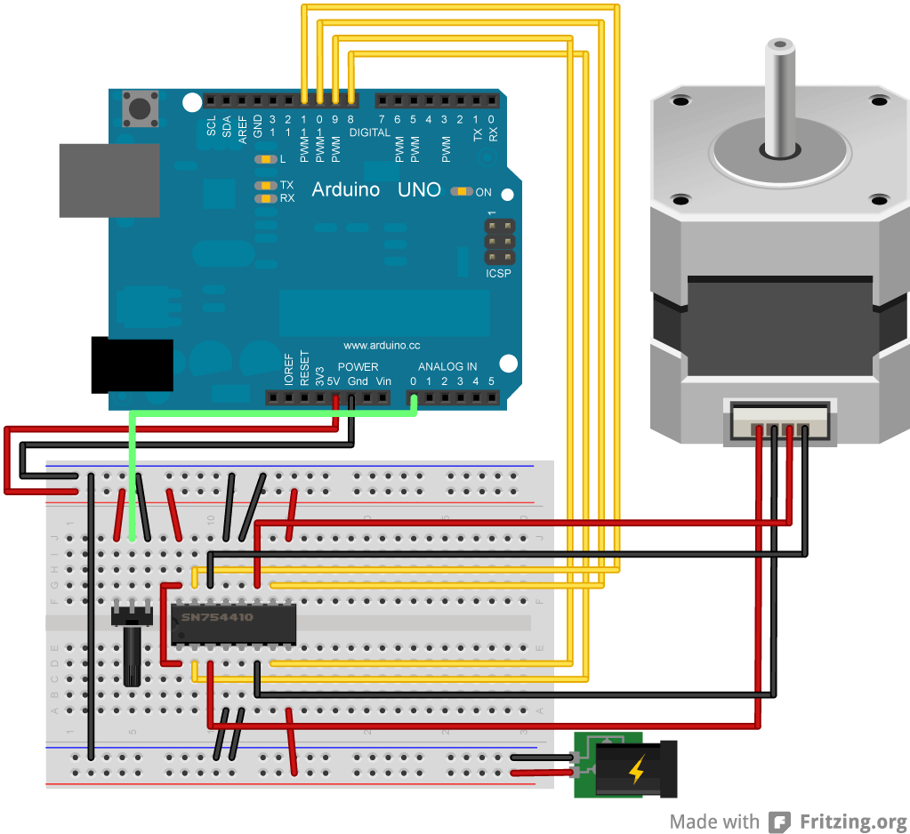
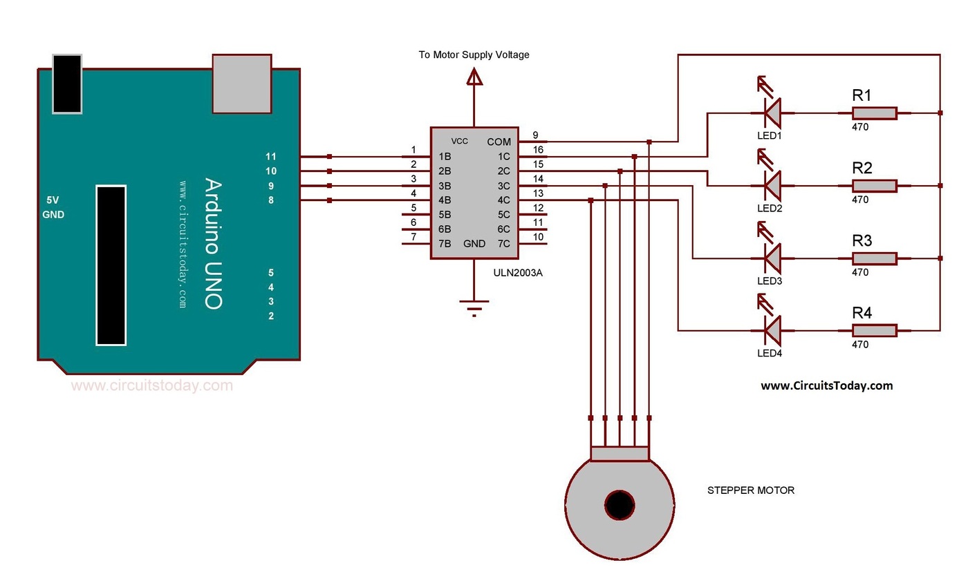
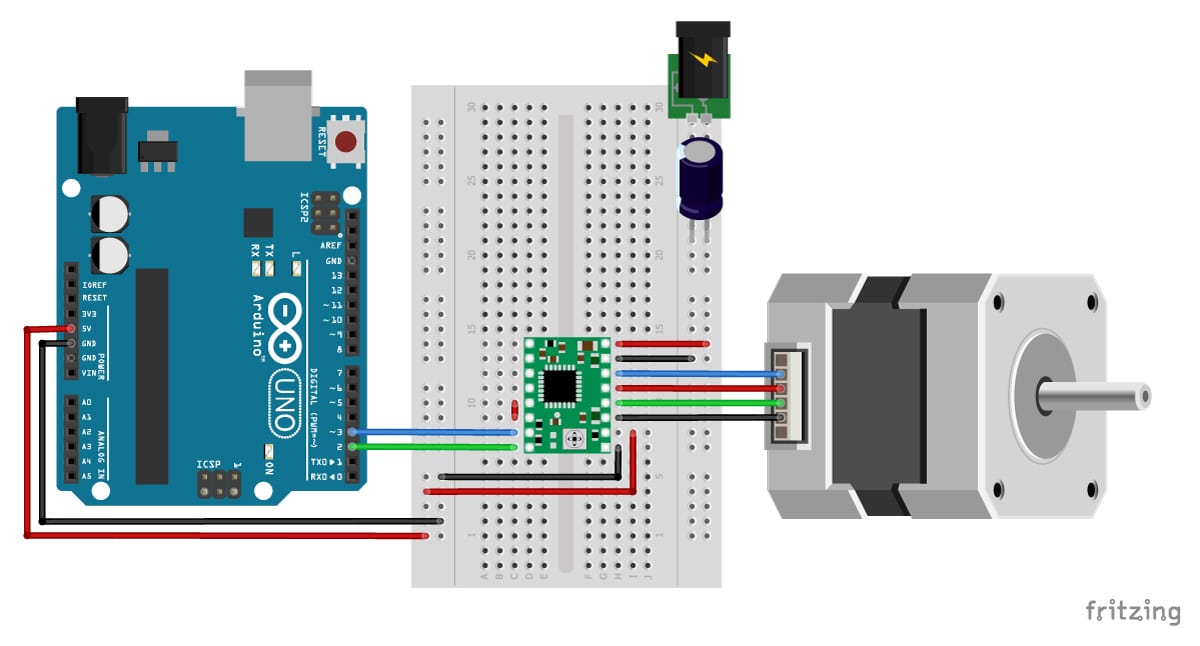
Unfortunately, stepper motors come in a variety of configurations and it is not always immediately obvious how to hook them up. On arduino website, the sample circuit�s stepper has 4 wires and is directly connected to a driver ic (a lmxxx), and the driver is connected to arduino. Stepper motor with l298n and arduino tutorial 4 examples 555 timer controller circuit a4988 driver how to wire motors bipolar control simple projects what is it sequence electrical4u. Since coils a and b on the diagram above are not connected, the resistance. 6 wire stepper motor wiring diagram.
 Source: rachelleogyaz.blogspot.com
If your stepper motor has 4 wires, it is a bipolar stepper motor. Rb_1509 5 wire fan motor diagram. Learning to control a stepper motor with the arduino motor shield. The basics on how stepper motor, stepper controller, and stepper driver work. But what the wiring should be?
 Source: wiringschemas.blogspot.com
1 phase motor wiring diagram 6 wire. If you have a unipolar drive, the terminal will be labeled a, b, c, d and a/c common, b/d common (or comm) notes: 1 phase motor wiring diagram 6 wire. Stepper motor with l298n and arduino tutorial 4 examples 555 timer controller circuit a4988 driver how to wire motors bipolar control simple projects what is it sequence electrical4u. The 4 wires, 5 wires and 6 wires stepper motors).
 Source: motorcyclepict.co
Lin engineering step motors are available with either 2 coil bipolar or 4 coil unipolar windings. The basics on how stepper motor, stepper controller, and stepper driver work. You can always depend on wiring diagram being an crucial reference that can assist you to conserve time and cash. A two phase bipolar stepper motor will have 4 leads. Here, we will talk about the most common motors:
 Source: untpikapps.com
The following diagram shows the connections to be made for an 8 wire series connected bipolar stepper motor. Here, we will talk about the most common motors: Nov 22, if your stepper motor has 4 wires, it is a bipolar stepper motor. Unlike a unipolar stepper motor a bipolar stepper only has a single winding per phase with no taps. Connecting this motor type is very straightforward and simply requires connecting the a and a� leads to the corresponding phase outputs on your motor drive.
 Source: electronicwings.com
The first element is symbol that indicate electrical element from the circuit. The 4 wires, 5 wires and 6 wires stepper motors). There are slight differences on how the different variant of stepper motors work (i.e. A circuit is generally composed by several components. Since coils a and b on the diagram above are not connected, the resistance between leads a1 and b1, or between a1 and b2 will be infinite.
 Source: diagramweb.net
Here, we will talk about the most common motors: Learning to control a stepper motor with the arduino motor shield. 4 5 6 and 8 wire stepper motors. Here, we will talk about the most common motors: There are just two things which are going to be found in any 4 wire motor wiring diagram.
 Source: youtube.com
At the end of this post, we share a stepper motor wiring cheatsheet to make this easier. So do check out my other instructable videos on these motors to learn more. Learning to control a stepper motor with the arduino motor shield. Since coils a and b on the diagram above are not connected, the resistance between leads a1 and b1, or between a1 and b2 will be infinite. While connecting a four wire bipolar stepper motor to a four terminal bipolar driver is pretty straight forward, you�ll really need to know what you�re doing in order to connect six or eight wire bipolar stepper motors to a bipolar driver.
 Source: wiringschemas.blogspot.com
While connecting a four wire bipolar stepper motor to a four terminal bipolar driver is pretty straight forward, you�ll really need to know what you�re doing in order to connect six or eight wire bipolar stepper motors to a bipolar driver. The following diagram shows the connections to be made for an 8 wire series connected bipolar stepper motor. The only thing you need to identify is the two pairs of wires which are connected to each of the two coils. 4 wire stepper motor driver circuit diagram wiring diagram line wiring diagram. One coil gets connected to out1 and out2 and the.
This site is an open community for users to share their favorite wallpapers on the internet, all images or pictures in this website are for personal wallpaper use only, it is stricly prohibited to use this wallpaper for commercial purposes, if you are the author and find this image is shared without your permission, please kindly raise a DMCA report to Us.
If you find this site beneficial, please support us by sharing this posts to your own social media accounts like Facebook, Instagram and so on or you can also bookmark this blog page with the title 4 wire bipolar stepper motor wiring diagram by using Ctrl + D for devices a laptop with a Windows operating system or Command + D for laptops with an Apple operating system. If you use a smartphone, you can also use the drawer menu of the browser you are using. Whether it’s a Windows, Mac, iOS or Android operating system, you will still be able to bookmark this website.


