Your Ford ballast resistor wiring diagram images are ready in this website. Ford ballast resistor wiring diagram are a topic that is being searched for and liked by netizens now. You can Download the Ford ballast resistor wiring diagram files here. Find and Download all free vectors.
If you’re searching for ford ballast resistor wiring diagram images information linked to the ford ballast resistor wiring diagram topic, you have pay a visit to the right site. Our website always gives you suggestions for seeking the highest quality video and picture content, please kindly hunt and locate more informative video articles and images that fit your interests.
Ford Ballast Resistor Wiring Diagram. The yellow wire is the signal for a tachometer. Ford ballast resistor wiring diagram. As i remember, a full 12v goes to the box/dist; Ford tractor ignition wiring diagram allis chalmers wd 12 volt alternator ford tractors tractors.
 Ford Ballast Resistor Wiring Diagram For Your Needs From dentistmitcham.com
For instance , if a module is usually powered up and it also sends out a signal of fifty percent the voltage and the technician does not know this, he would think he. One wire goes to the bottom stud on the terminal block & the other goes to the stud on right side of the resistor. But a resistor is used just for the ford coil of that era. 8n ford tractor wiring diagram eyelash me. One ought to never attempt working on electrical electrical wiring without knowing typically the below tips & tricks followed simply by even the the majority of experienced electrician. Key to wiring diagrams below.
3679f ford 800 pertronix ignitor wiring diagram digital.
Ford ballast resistor wiring diagram pictures. Next connect the white wire to the “i” terminal on the starter solenoid. Images december 29, 2019 post a comment coil pack wiring diagram anvelopesecondhand net. Diagram attached for wiring of points dizzy and coil with ballast resistor. Bypass any resistance unit to provide full 12v key on power to the coil and module. Depends on which ballast resistor being used locate your wiring diagram here trace out both start run circuits on a sheet of paper then locate both.
 Source: cars-trucks24.blogspot.com
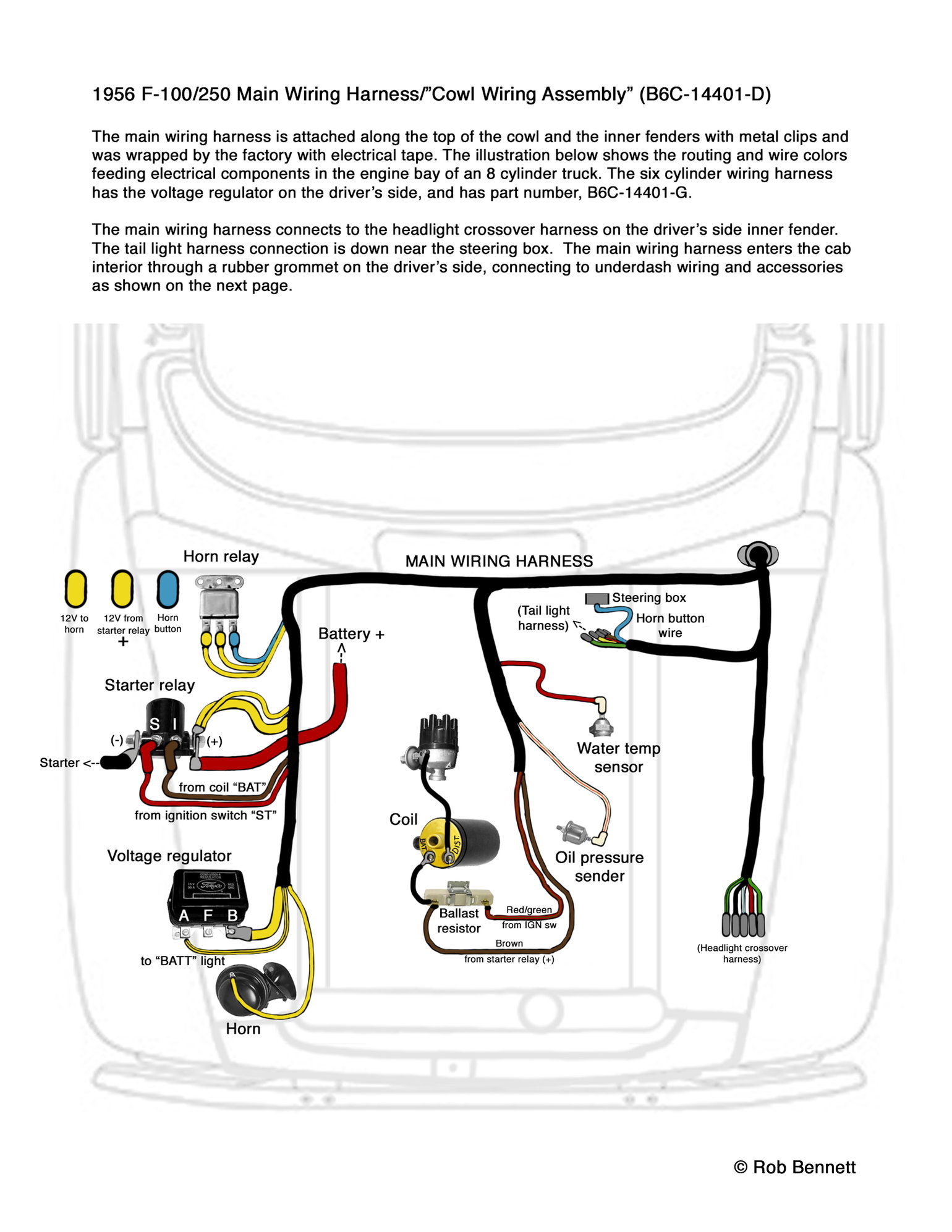
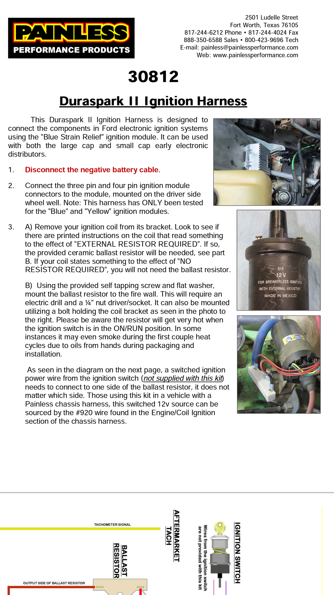
Ford started using the ballast resistor wire with the 1960 models. This simple system is easy for even the novice mechanic to wire. 8n ford tractor wiring diagram eyelash me. Diagram attached for wiring of points dizzy and coil with ballast resistor. Connect the red/green wire to the output side of the ballast resistor.
 Source: mgbreakers.com
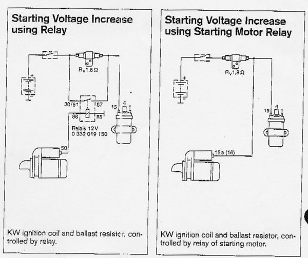
8n ford tractor wiring diagram eyelash me. Ford ballast resistor wiring diagram to properly read a electrical wiring diagram, one offers to learn how the particular components in the system operate. In a points type ignition the ballast resistor would help to keep the spark down and the coil from being burned up too quickly. Diagram attached for wiring of points dizzy and coil with ballast resistor. This page links directly to all of my 6 volt and 12 volt wiring diagrams.
 Source: sl113.org
Ford started using the ballast resistor wire with the 1960 models. Ford ballast resistor wiring diagram to properly read a electrical wiring diagram, one offers to learn how the particular components in the system operate. Next connect the white wire to the “i” terminal on the starter solenoid. Now look at your terminal block & resistor. W/ wrap around back rest.
Source: forabodiesonly.com
You will see a nice hot spark out of the secondary. The coil gets a full momentary 12volts in the start position to give you a hotter spark during start ups. For instance , if a module is usually powered up and it also sends out a signal of fifty percent the voltage and the technician does not know this, he would think he. Here is a picture gallery about ignition coil ballast resistor wiring diagram complete with the description of the image, please find the image you need. Now look at your terminal block & resistor.
 Source: schematron.org
Ignition coil ballast resistor wiring diagram with ignition coil ballast resistor wiring diagram, image size 609 x 360 px, and to view image details please click the image. Attach the resistor to the two on the top. The coil gets a full momentary 12volts in the start position to give you a hotter spark during start ups. You will see a nice hot spark out of the secondary. Diagram attached for wiring of points dizzy and coil with ballast resistor.
 Source: kelvin-okl.blogspot.com
In a points type ignition the ballast resistor would help to keep the spark down and the coil from being burned up too quickly. One second and ill pull up the wiring diagram. You will see a nice hot spark out of the secondary. Ford ballast resistor wiring diagram by prof. A resistor that has the property of increasing in resistance as current flowing through it increases and decreasing in resistance as current decreases.
 Source: automotorpad.com
Strip 1/2 inch of insulation from each end of this wire and crimp a connector onto each end. Leak may be in your ballast resistor connections or your ignition (key) switch. Key to wiring diagrams below. Ford ballast resistor wiring diagram. Run through a ballast resistor or wire.
 Source: faceitsalon.com
Links to other sites often break when they rename or move files. Ford ballast resistor wiring diagram. Depends on which ballast resistor being used locate your wiring diagram here trace out both start run circuits on a sheet of paper then locate both. Ford ballast resistor wiring diagram oleh anonim mei 04, 2020 posting komentar coil pack wiring diagram anvelopesecondhand net. The yellow wire is the signal for a tachometer.
 Source: pinterest.com
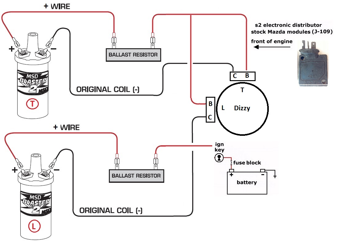
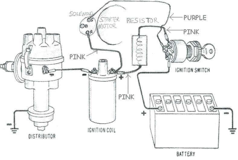
Images december 29, 2019 post a comment coil pack wiring diagram anvelopesecondhand net. Here is a picture gallery about ignition coil ballast resistor wiring diagram complete with the description of the image, please find the image you need. Ballast resistor wiring diagram points. A resistor that has the property of increasing in resistance as current flowing through it increases and decreasing in resistance as current decreases. Connect one side of the ballast resistor to the positive side of the coil.
 Source: nopistons.com
You will see a nice hot spark out of the secondary. This page links directly to all of my 6. Connect one side of the ballast resistor to the positive side of the coil. You will see a nice hot spark out of the secondary. Ballast resistor wiring diagram points.
 Source: yourmechanic.com
Pertronix electronic ignition wiring diagram ford. This page links directly to all of my 6. Electrical electrical wiring is really a potentially hazardous task if carried out improperly. Ballast resistor or in the case of stock ford wiring, a resistor wire, cuts the voltage to the coil to 6volts in the run position of the ignition key (longer coil life). Nhtc45d, nh lb75b, ford jubilee i�ve even seen one diagram where a lamp is installed in series with p1 so contact points and the ballast resistor or internal resistor in the coil.
 Source: facybulka.me
Ford ballast resistor wiring diagram oleh anonim mei 04, 2020 posting komentar coil pack wiring diagram anvelopesecondhand net. Ford ballast resistor wiring diagram from lh6.googleusercontent.com effectively read a wiring diagram, one provides to learn how typically the components within the system operate. 3679f ford 800 pertronix ignitor wiring diagram digital. Because of this, i added a backup ignition box using a duraspark box. Accel points eliminator wiring diagram using oem primary resistance wire.
 Source: tokachi1969.blogspot.com
Ford ballast resistor wiring diagram oleh anonim juni 06, 2020 posting komentar coil pack wiring diagram anvelopesecondhand net. Print the wiring diagram off plus use highlighters to trace the signal. One wire goes to the bottom stud on the terminal block & the other goes to the stud on right side of the resistor. Ford ballast resistor wiring diagram april 04, 2018 get link; This page links directly to all of my 6.
 Source: dentistmitcham.com
3679f ford 800 pertronix ignitor wiring diagram digital. Connect one side of the ballast resistor to the positive side of the coil. Leak may be in your ballast resistor connections or your ignition (key) switch. Now look at your terminal block & resistor. Diagram attached for wiring of points dizzy and coil with ballast resistor.
Source: dentistmitcham.com
The car does have the fuse block and resistor under the dash. One ought to never attempt working on electrical electrical wiring without knowing typically the below tips & tricks followed simply by even the the majority of experienced electrician. The yellow wire is the signal for a tachometer. How to install an msd 6a digital ignition module on your. Cut a piece of wire long enough to reach from the other terminal of the ballast resistor to the bat, + or b+ terminal of the coil.
 Source: cars-trucks24.blogspot.com
3679f ford 800 pertronix ignitor wiring diagram digital. Ford ballast resistor wiring diagram by prof. How to install an msd 6a digital ignition module on your. One wire goes to the bottom stud on the terminal block & the other goes to the stud on right side of the resistor. The yellow wire is the signal for a tachometer.
 Source: faceitsalon.com
Electrical electrical wiring is really a potentially hazardous task if carried out improperly. 3679f ford 800 pertronix ignitor wiring diagram digital. Next connect the white wire to the “i” terminal on the starter solenoid. As i remember, a full 12v goes to the box/dist; Connect one side of the ballast resistor to the positive side of the coil.
 Source: animemusic696.blogspot.com
In a points type ignition the ballast resistor would help to keep the spark down and the coil from being burned up too quickly. Ford ballast resistor wiring diagram from lh6.googleusercontent.com effectively read a wiring diagram, one provides to learn how typically the components within the system operate. As i remember, a full 12v goes to the box/dist; Depends on which ballast resistor being used locate your wiring diagram here trace out both start run circuits on a sheet of paper then locate both. In a points type ignition the ballast resistor would help to keep the spark down and the coil from being burned up too quickly.
This site is an open community for users to share their favorite wallpapers on the internet, all images or pictures in this website are for personal wallpaper use only, it is stricly prohibited to use this wallpaper for commercial purposes, if you are the author and find this image is shared without your permission, please kindly raise a DMCA report to Us.
If you find this site good, please support us by sharing this posts to your favorite social media accounts like Facebook, Instagram and so on or you can also save this blog page with the title ford ballast resistor wiring diagram by using Ctrl + D for devices a laptop with a Windows operating system or Command + D for laptops with an Apple operating system. If you use a smartphone, you can also use the drawer menu of the browser you are using. Whether it’s a Windows, Mac, iOS or Android operating system, you will still be able to bookmark this website.

