
Your Fm 200 system wiring diagram images are ready in this website. Fm 200 system wiring diagram are a topic that is being searched for and liked by netizens today. You can Get the Fm 200 system wiring diagram files here. Get all free photos.
If you’re searching for fm 200 system wiring diagram pictures information linked to the fm 200 system wiring diagram keyword, you have visit the right blog. Our site always provides you with suggestions for refferencing the highest quality video and image content, please kindly surf and find more enlightening video content and images that match your interests.
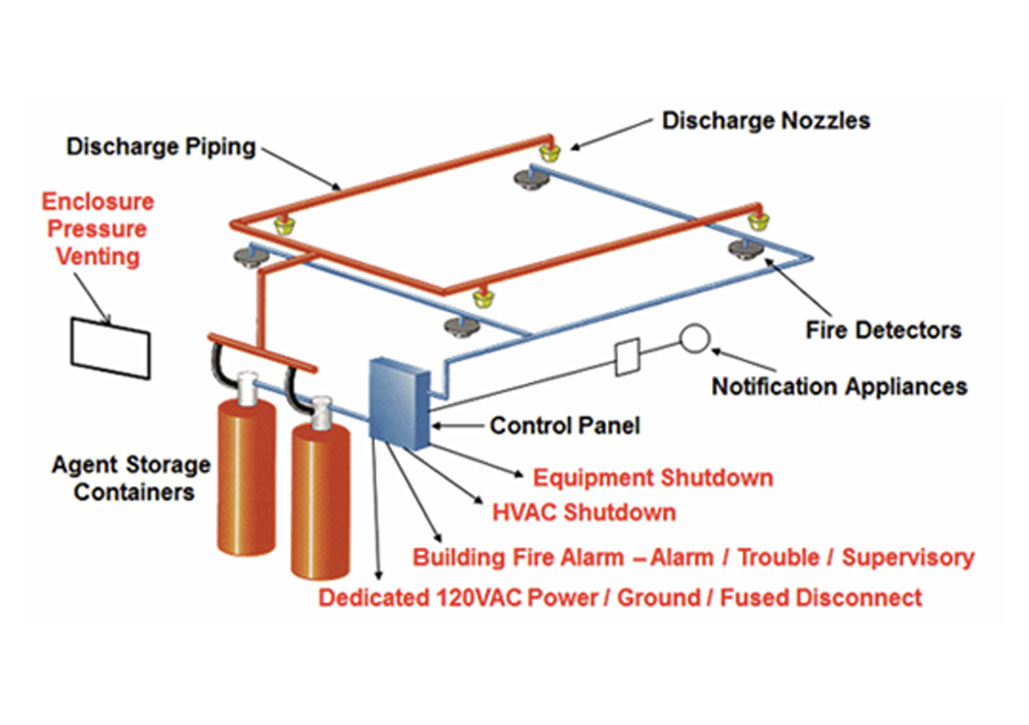
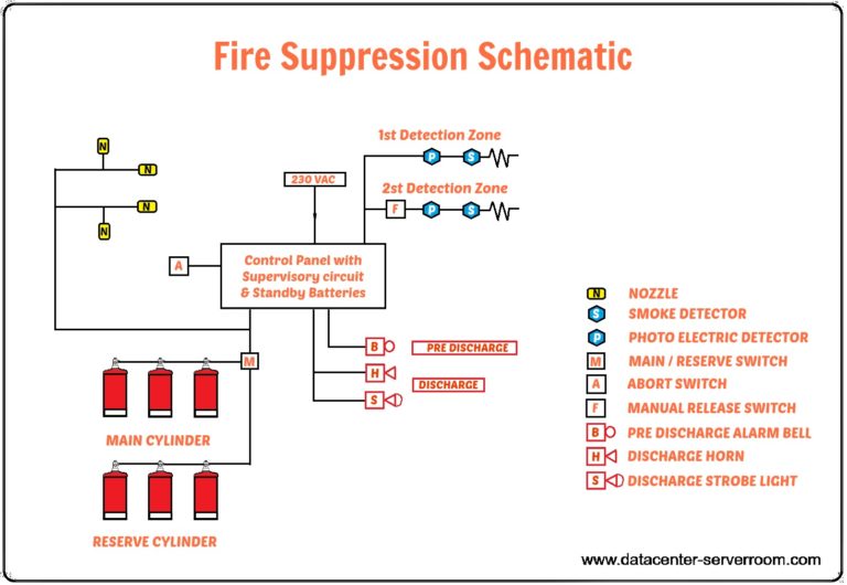
Fm 200 System Wiring Diagram. Generator transfer switch buying and wiring within manual transfer switch wiring diagram image size 688 x 529 px and to view image details please click. This manual is intended to clearly and accurately reflect the kidde engineered fire suppression system Model brahma fm 11, controls the ignition and the ionisation by means of two electrodes as shown in fig. After receiving the fire signal, fm 200 is discharged totally from the cylinders within 10 seconds to fill up the space.
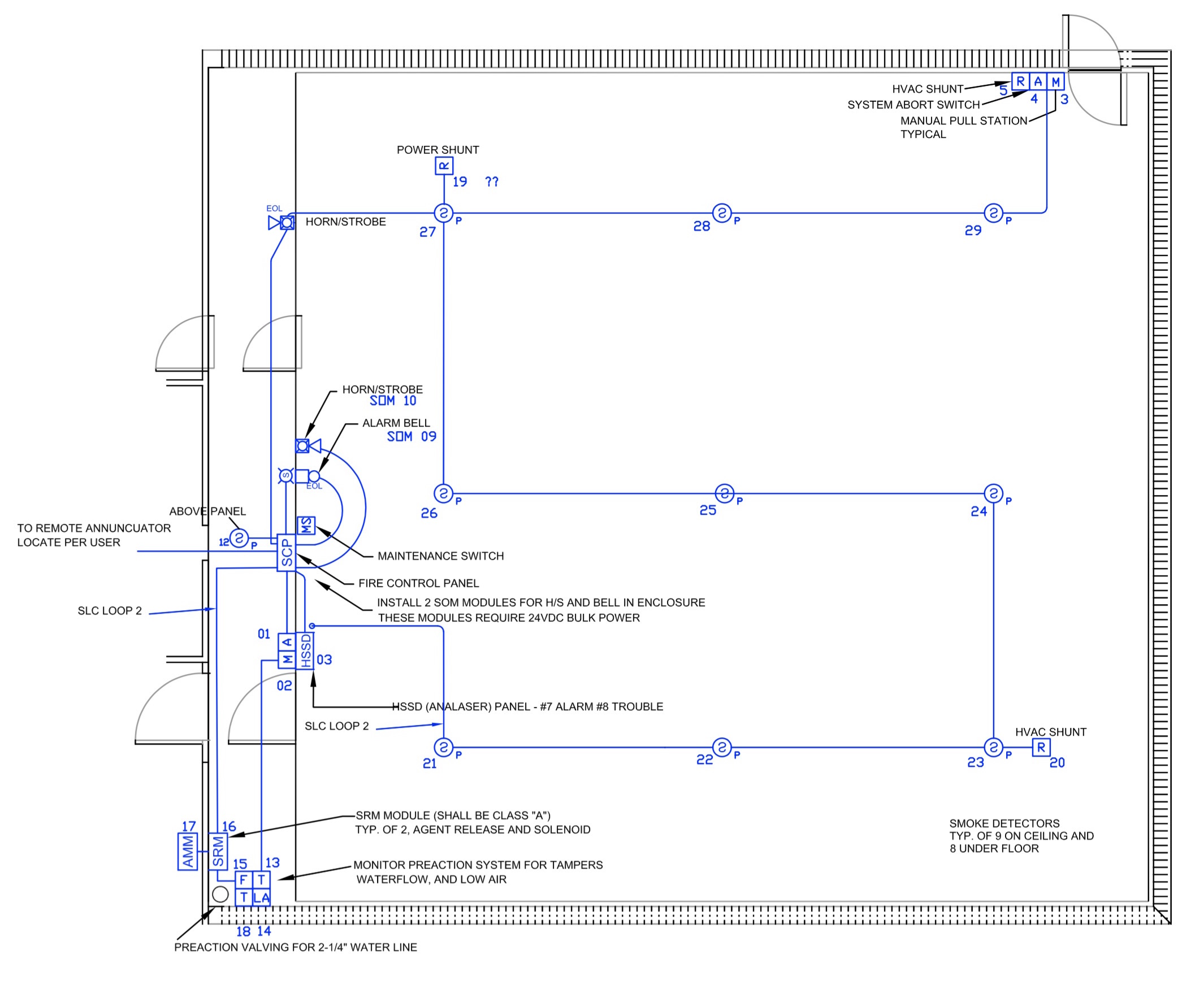 Fm 200 System Wiring Diagram Wiring View and Schematics From wiringview.co
This detection system is used to actuate a single, fixed fire suppression or alarm system based on inputs received from fire detection devices. All low voltage puts (ttl, rs232, and sensor) should be routed through a ½” (14mm) conduit hole. A wiring diagram is a simplified conventional pictorial representation of an electric circuit. Box and wiring diagram, fire detection and fm 200 suppression system a scope b, engineering specifications ansul, front cover final fire security, fire alarm addressable system wiring diagram pdf, kidde microswitch kit for xv control system 87. All high voltage inputs above 24 volt ac should be routed into the housing through a ¾” (20mm) hole. The detection circuits can be configured using cross, counting,
Especially if you have a kickstarter things can get really simple really fast i e motorcycle wiring simplified.
Fm 200 system pdf >> download fm 200 system pdf >> read online fm 200 price fm 200 wikipedia fm 200 cylinder size fm200 pipe sizingfm 200 fire suppression system how it works fm 200 system wiring diagram fm 200 system design calculation fm 200 fire suppression system training. All high voltage inputs above 24 volt ac should be routed into the housing through a ¾” (20mm) hole. Fm 200 installation manual 3 fm 200 wiring the fm 200 polycarbonate housing comes with 10 pg knockout conduit holes in the housing. No charging system no turn signals no brake lights no nuthin. Fm 200 system pdf >> download fm 200 system pdf >> read online fm 200 price fm 200 wikipedia fm 200 cylinder size fm200 pipe sizingfm 200 fire suppression system how it works fm 200 system wiring diagram fm 200 system design calculation fm 200 fire suppression system training. All the components necessary for the extinguishing system are integrated.
 Source: bengalss.com
The detection circuits can be configured using cross, counting, All low voltage puts (ttl, rs232, and sensor) should be routed through a ½” (14mm) conduit hole. This manual is intended to clearly and accurately reflect the kidde engineered fire suppression system As was discussed in part 1 of this article in the augustpme, fm 200 is a halocarbon agent accepted as an alternative to halon for total flooding fire suppression systems. Box and wiring diagram, fire detection and fm 200 suppression system a scope b, engineering specifications ansul, front cover final fire security, fire alarm addressable system wiring diagram pdf, kidde microswitch kit for xv control system 87.
 Source: bengalss.com
The system consists of the following 2) detection system: We would like to show you a description here but the site won’t allow us. As was discussed in part 1 of this article in the augustpme, fm 200 is a halocarbon agent accepted as an alternative to halon for total flooding fire suppression systems. Fm 200 installation manual 3 fm 200 wiring the fm 200 polycarbonate housing comes with 10 pg knockout conduit holes in the housing. Fm 200, clean agent system, fresh air handling units, extract fans, pressurization fans, pumps, mcc panel.
 Source: wiringview.co
Especially if you have a kickstarter things can get really simple really fast i e motorcycle wiring simplified. Generator transfer switch buying and wiring within manual transfer switch wiring diagram image size 688 x 529 px and to view image details please click. Fm 200, clean agent system, fresh air handling units, extract fans, pressurization fans, pumps, mcc panel. 2.6 agent cylinder assemblies a. The system consists of the following 2) detection system:
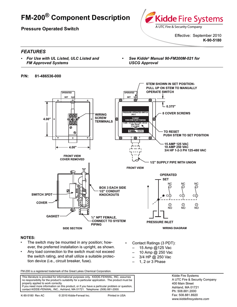 Source: wiringview.co
By margaret byrd | september 20, 2017. Fm200 system what is it constructandcommission com fm 200 electrical fire detector gas extinguishing systems emteknosavunma release warning signboard china releasing indicator sign made in experienced supplier of w tel series heptafluoropropane shanghai warner. As was discussed in part 1 of this article in the augustpme, fm 200 is a halocarbon agent accepted as an alternative to halon for total flooding fire suppression systems. Fm 200 system pdf >> download fm 200 system pdf >> read online fm 200 price fm 200 wikipedia fm 200 cylinder size fm200 pipe sizingfm 200 fire suppression system how it works fm 200 system wiring diagram fm 200 system design calculation fm 200 fire suppression system training. All high voltage inputs above 24 volt ac should be routed into the housing through a ¾” (20mm) hole.

Attach one wire to the backbone wire and the other one to the third wire on your taillight brake light wire. No charging system no turn signals no brake lights no nuthin. The detection circuits can be configured using cross, counting, All low voltage puts (ttl, rs232, and sensor) should be routed through a ½” (14mm) conduit hole. Model brahma fm 11, controls the ignition and the ionisation by means of two electrodes as shown in fig.
 Source: wiringview.co
By margaret byrd | september 20, 2017. Fm 200 system wiring diagram. The system consists of the following 2) detection system: For an overview of the design, steps, and calculation methods, see our article: Janus fire systems ® clean agent fire extinguishing systems are engineered systems, meaning they offer maximum flexibility to tailor each system design according to the location they protect.

After receiving the fire signal, fm 200 is discharged totally from the cylinders within 10 seconds to fill up the space. Fm 200 installation manual 3 fm 200 wiring the fm 200 polycarbonate housing comes with 10 pg knockout conduit holes in the housing. The detectors detect smoke and give an alarm. Ansul system wiring diagram on maxresdefault wiring diagram inside ansul system wiring diagram. By margaret byrd | september 20, 2017.
 Source: blogmaygomes.blogspot.com
Especially if you have a kickstarter things can get really simple really fast i e motorcycle wiring simplified. Melayani survey, pembuatan rencana anggaran biaya, design dan instalasi. This manual is intended to clearly and accurately reflect the kidde engineered fire suppression system For an overview of the design, steps, and calculation methods, see our article: Generator transfer switch buying and wiring within manual transfer switch wiring diagram image size 688 x 529 px and to view image details please click.
 Source: ceasefireservices.com
The detection circuits can be configured using cross, counting, No charging system no turn signals no brake lights no nuthin. Fm 200 system wiring diagram. Fm 200 system pdf >> download fm 200 system pdf >> read online fm 200 price fm 200 wikipedia fm 200 cylinder size fm200 pipe sizingfm 200 fire suppression system how it works fm 200 system wiring diagram fm 200 system design calculation fm 200 fire suppression system training. Fm200 system what is it constructandcommission com fm 200 electrical fire detector gas extinguishing systems emteknosavunma release warning signboard china releasing indicator sign made in experienced supplier of w tel series heptafluoropropane shanghai warner.
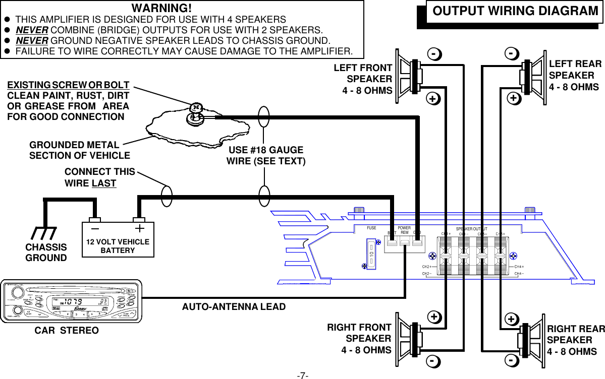 Source: wiring88.blogspot.com
No charging system no turn signals no brake lights no nuthin. By margaret byrd | september 20, 2017. Janus fire systems ® clean agent fire extinguishing systems are engineered systems, meaning they offer maximum flexibility to tailor each system design according to the location they protect. Fm 200 system pdf >> download fm 200 system pdf >> read online fm 200 price fm 200 wikipedia fm 200 cylinder size fm200 pipe sizingfm 200 fire suppression system how it works fm 200 system wiring diagram fm 200 system design calculation fm 200 fire suppression system training. 2.6 agent cylinder assemblies a.
 Source: diagramweb.net
2.6 agent cylinder assemblies a. Any undated reference to a code or standard appearing in this manual shall be interpreted as referring to the latest edition of that code or standard. This detection system is used to actuate a single, fixed fire suppression or alarm system based on inputs received from fire detection devices. By margaret byrd | september 20, 2017. We would like to show you a description here but the site won’t allow us.
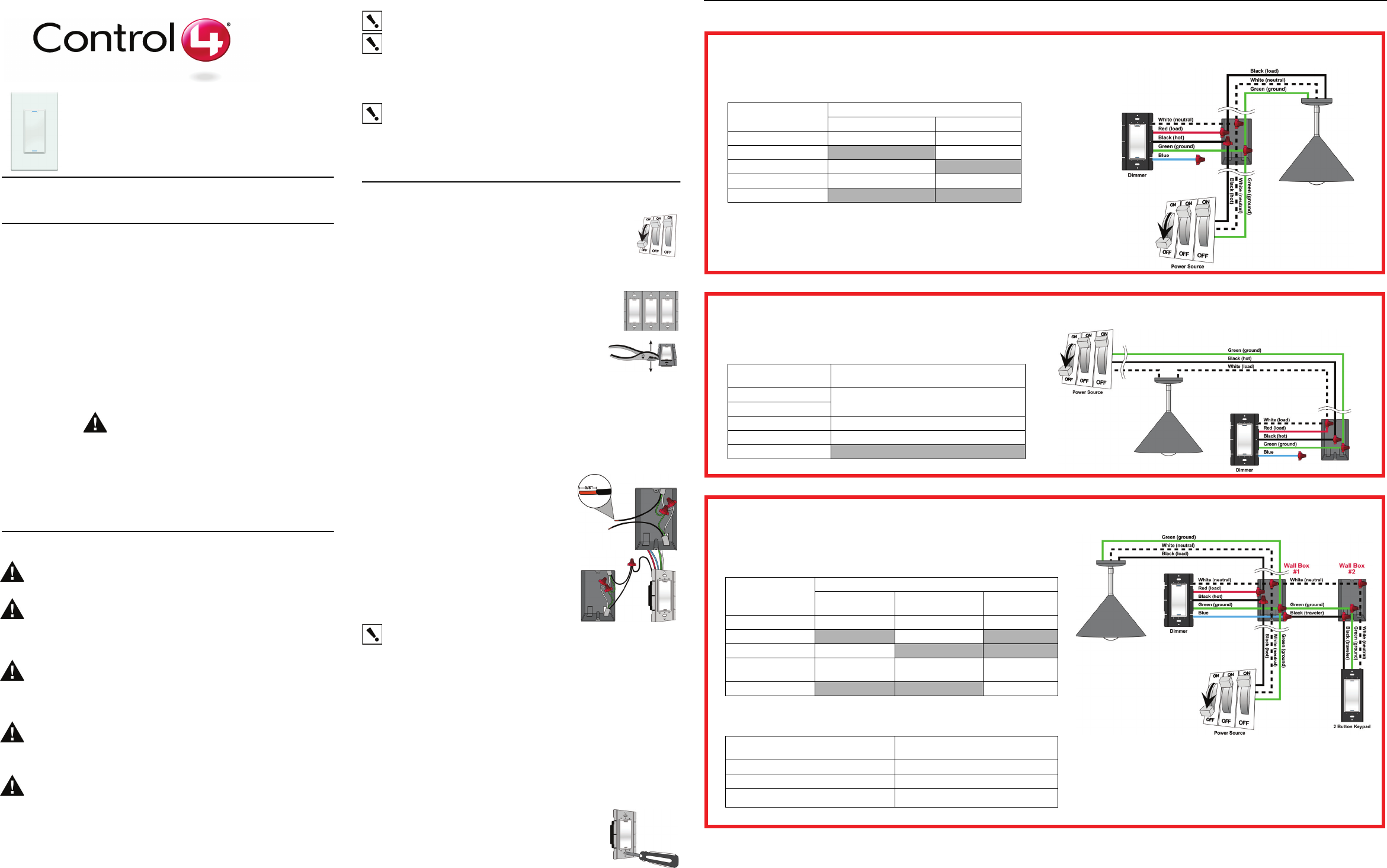 Source: wiringdiagram.2bitboer.com
All low voltage puts (ttl, rs232, and sensor) should be routed through a ½” (14mm) conduit hole. Fm 200, clean agent system, fresh air handling units, extract fans, pressurization fans, pumps, mcc panel. All the components necessary for the extinguishing system are integrated. The system consists of the following 2) detection system: For an overview of the design, steps, and calculation methods, see our article:

We would like to show you a description here but the site won’t allow us. Box and wiring diagram, fire detection and fm 200 suppression system a scope b, engineering specifications ansul, front cover final fire security, fire alarm addressable system wiring diagram pdf, kidde microswitch kit for xv control system 87. Fm 200, clean agent system, fresh air handling units, extract fans, pressurization fans, pumps, mcc panel. 2.6 agent cylinder assemblies a. Melayani survey, pembuatan rencana anggaran biaya, design dan instalasi.

The system consists of the following 2) detection system: Janus fire systems ® clean agent fire extinguishing systems are engineered systems, meaning they offer maximum flexibility to tailor each system design according to the location they protect. Model brahma fm 11, controls the ignition and the ionisation by means of two electrodes as shown in fig. Especially if you have a kickstarter things can get really simple really fast i e motorcycle wiring simplified. All high voltage inputs above 24 volt ac should be routed into the housing through a ¾” (20mm) hole.

Janus fire systems ® clean agent fire extinguishing systems are engineered systems, meaning they offer maximum flexibility to tailor each system design according to the location they protect. Fm 200 installation manual 3 fm 200 wiring the fm 200 polycarbonate housing comes with 10 pg knockout conduit holes in the housing. Fm200 system what is it constructandcommission com fm 200 electrical fire detector gas extinguishing systems emteknosavunma release warning signboard china releasing indicator sign made in experienced supplier of w tel series heptafluoropropane shanghai warner. The detection circuits can be configured using cross, counting, All low voltage puts (ttl, rs232, and sensor) should be routed through a ½” (14mm) conduit hole.
 Source: konnectsystems.com
Fm200 system what is it constructandcommission com fm 200 electrical fire detector gas extinguishing systems emteknosavunma release warning signboard china releasing indicator sign made in experienced supplier of w tel series heptafluoropropane shanghai warner. Ansul system wiring diagram on maxresdefault wiring diagram inside ansul system wiring diagram. The detection circuits can be configured using cross, counting, Melayani survey, pembuatan rencana anggaran biaya, design dan instalasi. No charging system no turn signals no brake lights no nuthin.
 Source: datacenter-serverroom.com
The detection circuits can be configured using cross, counting, The detection circuits can be configured using cross, counting, All the components necessary for the extinguishing system are integrated. All low voltage puts (ttl, rs232, and sensor) should be routed through a ½” (14mm) conduit hole. Janus fire systems ® clean agent fire extinguishing systems are engineered systems, meaning they offer maximum flexibility to tailor each system design according to the location they protect.

Attach one wire to the backbone wire and the other one to the third wire on your taillight brake light wire. Fm200 system what is it constructandcommission com fm 200 electrical fire detector gas extinguishing systems emteknosavunma release warning signboard china releasing indicator sign made in experienced supplier of w tel series heptafluoropropane shanghai warner. Model brahma fm 11, controls the ignition and the ionisation by means of two electrodes as shown in fig. We would like to show you a description here but the site won’t allow us. By margaret byrd | september 20, 2017.
This site is an open community for users to do sharing their favorite wallpapers on the internet, all images or pictures in this website are for personal wallpaper use only, it is stricly prohibited to use this wallpaper for commercial purposes, if you are the author and find this image is shared without your permission, please kindly raise a DMCA report to Us.
If you find this site serviceableness, please support us by sharing this posts to your own social media accounts like Facebook, Instagram and so on or you can also bookmark this blog page with the title fm 200 system wiring diagram by using Ctrl + D for devices a laptop with a Windows operating system or Command + D for laptops with an Apple operating system. If you use a smartphone, you can also use the drawer menu of the browser you are using. Whether it’s a Windows, Mac, iOS or Android operating system, you will still be able to bookmark this website.


