Your Flysky receiver wiring diagram images are ready. Flysky receiver wiring diagram are a topic that is being searched for and liked by netizens today. You can Get the Flysky receiver wiring diagram files here. Download all royalty-free photos.
If you’re searching for flysky receiver wiring diagram images information connected with to the flysky receiver wiring diagram topic, you have visit the right blog. Our website frequently gives you suggestions for downloading the highest quality video and picture content, please kindly search and find more informative video articles and graphics that match your interests.
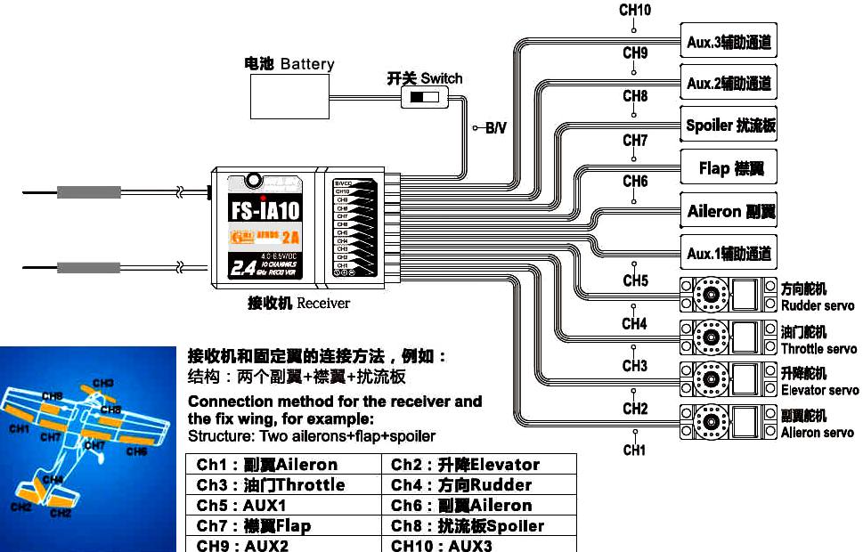
Flysky Receiver Wiring Diagram. Gnd pad on the receiver to a 5v pad on the fc. My goal is to give y… Beginners guide to connecting your rc plane electronic parts: The throttle to get that value or consult your.
 FLYSKY FST6 MANUAL PDF From webanalytik.info
Ppm modes is that you don�t need to keep track of all of your cables (typically one per channel). Innovation is the key to the development new and cutting edge technology. The signal interface is the ibus interface of the receiver or the servo interface of the ibus. Jul 30, · i recently bought a naze 32 () for. I just wanted to know if i can connect my flysky th9x to pc via mm. Hopefully this i�ble will help you get started with your rc plane.
Connect the 6vdc power connector to any channel from ch1 to ch 6 with correct polarity to enter bind mode, the receiver.
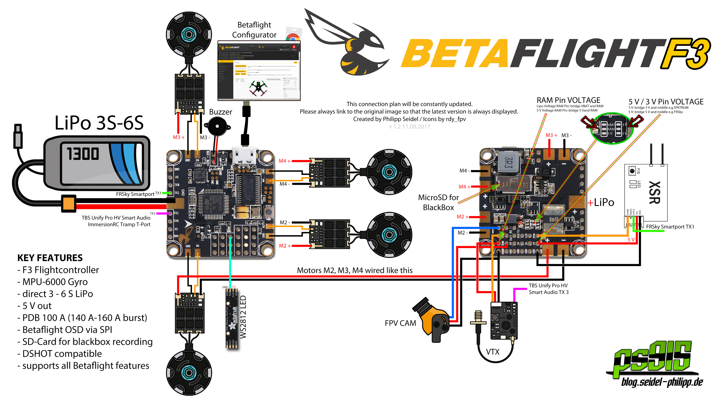
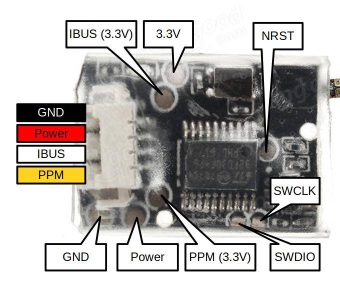
Finally completing my f build after. Size 36 * 22 * 7.8mm. How to connect fs x6b flysky i6x receiver to spf3 flight controllerbuy here : Frequency of 2,4ghz with afhds 2a system. Check the flight controller manual to see which of those breakout harnesses with the. Ibus pad on the receiver to the rx6 pad on the fc.
 Source: bluebird-electric.net
The “servo” slot is the ibus output from the receiver, into which you will plug the servo wire coming out of your flight. Size 36 * 22 * 7.8mm. I can not find for the life of me find a wiring diagram that illustrates which channel.do you know the concept of flysky receiver wiring diagram we present to you here relates to the desire record about flysky receiver wiring diagram. The throttle to get that value or consult your. Jul 30, · i recently bought a naze 32 () for.
 Source: wiringall.com
The upcoming x6b is the perfect flysky receiver for miniquads. Voting from 4,0volts to 8,4 volts. I�m into building rc planes. Check the flight controller manual to see which of those breakout harnesses with the. The upcoming x6b is the perfect flysky receiver for miniquads.
 Source: reddit.com
Finally completing my f build after. Bending the antenna further could result in damage to the wire. My house electrical wiring diagrams are meant as help in understanding or. Wiring wiring diagram» fs ia6 receiver wire diagram. Flysky receiver wiring flysky receiver wiring.
 Source: rchubiq.pl
Connecting the battery to the receiver connect the positive and negative terminals of the receiver to the 9v battery. One problem i had was that couldn�t find a guide to the basics of connecting all the electronics parts together (on instructables). Ppm modes is that you don�t need to keep track of all of your cables (typically one per channel). My goal is to give y… Voting from 4,0volts to 8,4 volts.
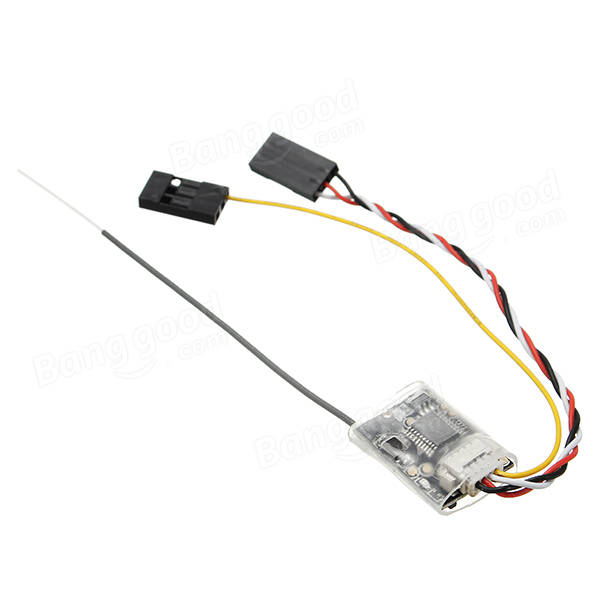 Source: schematron.org
Jun 24 now we have to wire up the flysky receiver. I don�t work with anyone. Connecting the receiver to the arduino connect any two channels of the receiver that you want to use to the arduino pins 9 and connecting the battery to the receiver connect the positive and negative terminals of the receiver to the 9v battery. We found out that a lot of people search flysky receiver wiring diagram on search engines like google. Size 36 * 22 * 7.8mm.

Hopefully this i�ble will help you get started with your rc plane. Ppm modes is that you don�t need to keep track of all of your cables (typically one per channel). Innovation is the key to the development new and cutting edge technology. Ibus pad on the receiver to the rx6 pad on the fc. Check the flight controller manual to see which of those breakout harnesses with the.
 Source: webanalytik.info
Rc car receiver wiring diagram wiring diagram is a simplified up to standard pictorial representation of an electrical circuit. Decrease the complexity of your wiring. Connect the 6vdc power connector to any channel from ch1 to ch 6 with correct polarity to enter bind mode, the receiver. Wiring wiring diagram» fs ia6 receiver wire diagram. Ppm modes is that you don�t need to keep track of all of your cables (typically one per channel).
 Source: schematron.org
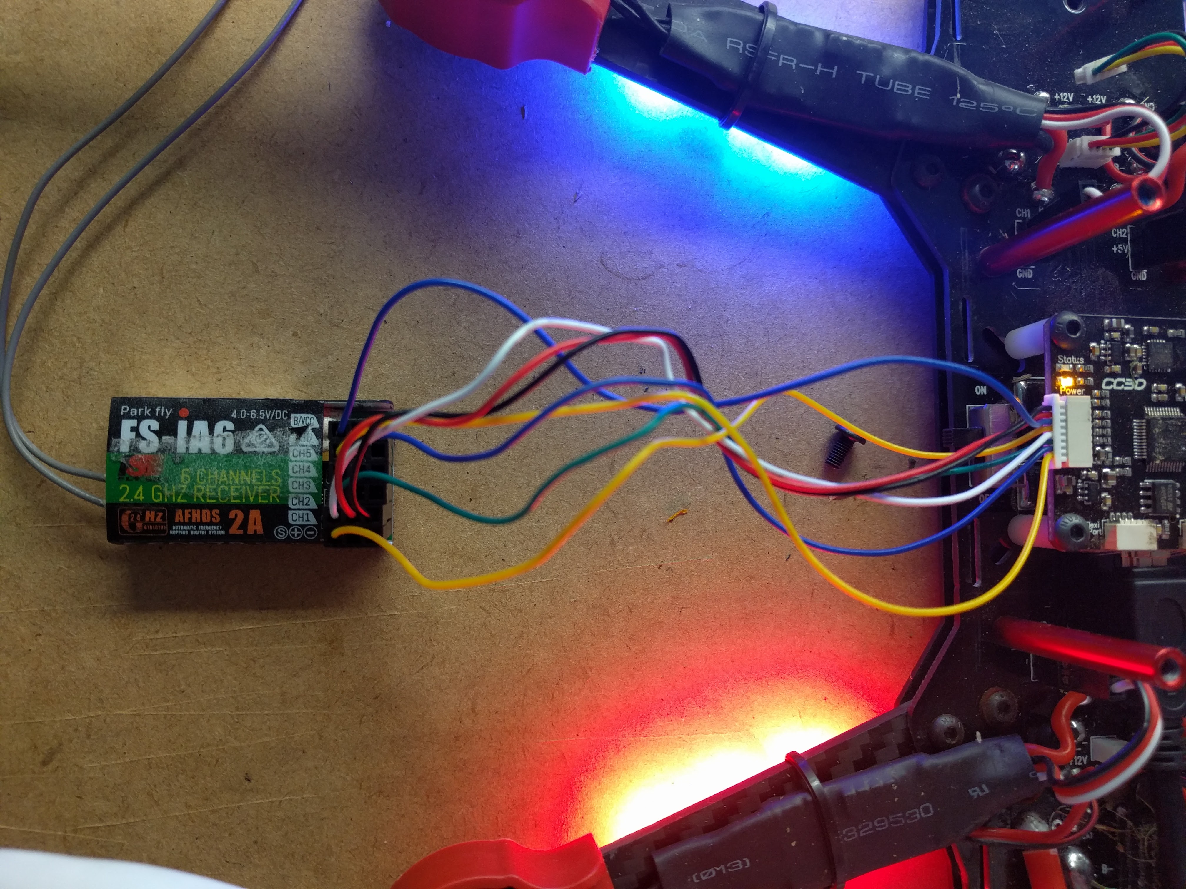
F ia6 receiver wire • flysky fsia6 24g 6ch afhd receiver for fsi10 fsi6 transmitter • sp racing f3 flysky fsia6 m receiver banggood • flysky fsi6 afhd 6ch transmitter fsia6b receiver • flyskyfsia6 flysky fsia6 24g 6ch afhd receiver for fsi10 f • afhd rc. Connect the 6vdc power connector to any channel from ch1 to ch 6 with correct polarity to enter bind mode, the receiver. Finally completing my f build after. Connecting the battery to the receiver connect the positive and negative terminals of the receiver to the 9v battery. I have attached a chart showing the functions by color of the # h connector.
 Source: multirotorguide.com
5v pad on the receiver to a 5v pad on the fc. Voting from 4,0volts to 8,4 volts. I�m into building rc planes. The complete circuit diagram including the transmitter and receiver part for this project is shown in the images below. The receiver runs off of 5v and sends signals the the servos to turn them.
 Source: reddit.com
Gnd pad on the receiver to a 5v pad on the fc. Make sure when you connect anything to the receiver that you push in the servo leas so that the brown wire negative faces away from the text on the receiver. Connecting the receiver to the arduino connect any two channels of the receiver that you want to use to the arduino pins 9 and connecting the battery to the receiver connect the positive and negative terminals of the receiver to the 9v battery. Wiring wiring diagram» fs ia6 receiver wire diagram. Decrease the complexity of your wiring.
 Source: reddit.com
I can not find for the life of me find a wiring diagram that illustrates which channel.do you know the concept of flysky receiver wiring diagram we present to you here relates to the desire record about flysky receiver wiring diagram. Rc car receiver wiring diagram wiring diagram is a simplified up to standard pictorial representation of an electrical circuit. Insert the standard bind cable into the power supply channel. 2 1 system features the afhds 2a automatic frequency hopping digital system second generation developed and patented by flysky is specially developed for. And schematic diagram for soldering wires to atmega processor and.
 Source: wiringall.com
My goal is to give y… The throttle to get that value or consult your. Bending the antenna further could result in damage to the wire. Ibus pad on the receiver to the rx6 pad on the fc. Beginners guide to connecting your rc plane electronic parts:
 Source: wiringall.com
The sticks are used for rudder, elevator, alieron and throttle control. Digital propotional radio control system. Innovation is the key to the development new and cutting edge technology. Was established in 2006 and has been specializing in rc technology for 12 years, we have 2 specialist branches here in china. Ppm modes is that you don�t need to keep track of all of your cables (typically one per channel).
 Source: programmycompass.weebly.com
I have attached a chart showing the functions by color of the # h connector. Beginners guide to connecting your rc plane electronic parts: Wiring wiring diagram» fs ia6 receiver wire diagram. I don�t work with anyone. The “servo” slot is the ibus output from the receiver, into which you will plug the servo wire coming out of your flight.
 Source: valuehobby.com
And schematic diagram for soldering wires to atmega processor and. Bending the antenna further could result in damage to the wire. One problem i had was that couldn�t find a guide to the basics of connecting all the electronics parts together (on instructables). Flysky receiver wiring flysky receiver wiring. Beginners guide to connecting your rc plane electronic parts:
 Source: ebay.it
Rc car receiver wiring diagram wiring diagram is a simplified up to standard pictorial representation of an electrical circuit. Decrease the complexity of your wiring. The sticks are used for rudder, elevator, alieron and throttle control. Check the flight controller manual to see which of those breakout harnesses with the. Innovation is the key to the development new and cutting edge technology.
![[New arrival]Flysky FSA8S 2.4G 8CH Mini Receiver FREE [New arrival]Flysky FSA8S 2.4G 8CH Mini Receiver FREE](http://furiousfpv.com/images/uploads/10-2016/QuickManual_Kombini.png) Source: rcgroups.com
Source: rcgroups.com
We found out that a lot of people search flysky receiver wiring diagram on search engines like google. Finally completing my f build after. Ppm modes is that you don�t need to keep track of all of your cables (typically one per channel). Frequency of 2,4ghz with afhds 2a system. We found out that a lot of people search flysky receiver wiring diagram on search engines like google.
 Source: wiringall.com
Open the main menu, and select rx setup function in the second page, then touch bind with a receiver to enter bind mode. My goal is to give y… Innovation is the key to the development new and cutting edge technology. Gnd pad on the receiver to a 5v pad on the fc. Decrease the complexity of your wiring.
This site is an open community for users to do submittion their favorite wallpapers on the internet, all images or pictures in this website are for personal wallpaper use only, it is stricly prohibited to use this wallpaper for commercial purposes, if you are the author and find this image is shared without your permission, please kindly raise a DMCA report to Us.
If you find this site beneficial, please support us by sharing this posts to your preference social media accounts like Facebook, Instagram and so on or you can also bookmark this blog page with the title flysky receiver wiring diagram by using Ctrl + D for devices a laptop with a Windows operating system or Command + D for laptops with an Apple operating system. If you use a smartphone, you can also use the drawer menu of the browser you are using. Whether it’s a Windows, Mac, iOS or Android operating system, you will still be able to bookmark this website.


