Your Flasher unit wiring diagram images are available in this site. Flasher unit wiring diagram are a topic that is being searched for and liked by netizens now. You can Download the Flasher unit wiring diagram files here. Download all royalty-free photos and vectors.
If you’re looking for flasher unit wiring diagram images information linked to the flasher unit wiring diagram interest, you have pay a visit to the ideal blog. Our website always gives you suggestions for viewing the maximum quality video and image content, please kindly surf and locate more enlightening video articles and images that match your interests.
Flasher Unit Wiring Diagram. You may be able to learn specifically if the projects should be completed, that makes it much easier for you to properly handle your. Wiring diagram arrives with numerous easy to stick to wiring diagram guidelines. The flasher unit is located in the battery compartment and has 5 pins which was made by denso. Yamaha g8 golf cart electric wiring diagram image for electrical system.
 18 Beautiful 3 Pin Flasher Relay Wiring Diagram From bosco-mylove.blogspot.com
2 pin flasher unit wiring diagram september 1, 2021. Installing turn signals electrical diagram electricity electrical wiring diagram. 24v flasher unit wiring diagram warning light micro hyundai starter relay 24v 5 pin truck relay 066500 2080 for sale hyundai starter relay manufacturer from china 109897198. It is intended to aid each of the average person in developing a correct program. 3 pin flasher unit wiring diagram 3 terminal flasher wiring with 3 pin flasher relay wiring diagram by admin from the thousand images on the internet regarding 3 pin flasher relay wiring diagram, we choices the very best series using ideal image resolution simply for you, and this pictures is usually considered one of graphics series inside our ideal images gallery in. 12 volt automotive indicator flasher unit relays by mail order uk.
With the ignition on, earth the tester and probe the feed wire connector:the lamp should light.
24v flasher unit wiring diagram warning light micro hyundai starter relay 24v 5 pin truck relay 066500 2080 for sale hyundai starter relay manufacturer from china 109897198. Find out the newest pictures of 4 pin flasher unit wiring diagram here, and also you can have the picture here simply. �i circuit circuit sb w switch o g g 8 light rear flasher (left) off on r off run front clutch switch meter light neutral light turn indicator tight high beam light w w b biy. The flasher unit is located in the battery compartment and has 5 pins which was made by denso. Simplest lamp flasher circuit technische website nsu motor hans homburg hot wire unit simple relay with ne555 timer better ility deeptronic flashers and hazards 3 pin led turn signal mgi sdware adjule 2 automotive gtsparkplugs circuitbest 24v diagram using two relays how to build a heavy duty 12 volt detailed description schematic bright hub. Automotive flashers gtsparkplugs and hazards relay ep27 flashing led 12v flasher motorcycle car france xenon 3 pin turn signal mgi sdware simple circuit with ne555 timer wiring using relays factory five racing forum technische website nsu motor hans homburg hot wire unit lamp malfunction indicator homemade projects the how signals work howstuffworks hazard.
Source: wiringdiagramsx.blogspot.com
This unit needs to be wired in conjunction with a suitable flasher unit and brake light switch. Yamaha g8 golf cart electric wiring diagram image for electrical system. Wiring diagram for 6 volt 3 prong flasher pdf. It really is meant to aid all the typical consumer in building a suitable method. We never store the image file in our host.
 Source: tops-stars.com
It really is meant to aid all the typical consumer in building a suitable method. Find out the newest pictures of 4 pin flasher unit wiring diagram here, and also you can have the picture here simply. This unit needs to be wired in conjunction with a suitable flasher unit and brake light switch. Power the unit from a negative lead from the battery or your hot terminal block on the firewall. 3 pin flasher unit wiring diagram 3 terminal flasher wiring with 3 pin flasher relay wiring diagram by admin from the thousand images on the internet regarding 3 pin flasher relay wiring diagram, we choices the very best series using ideal image resolution simply for you, and this pictures is usually considered one of graphics series inside our ideal images gallery in.
 Source: wiringview.co
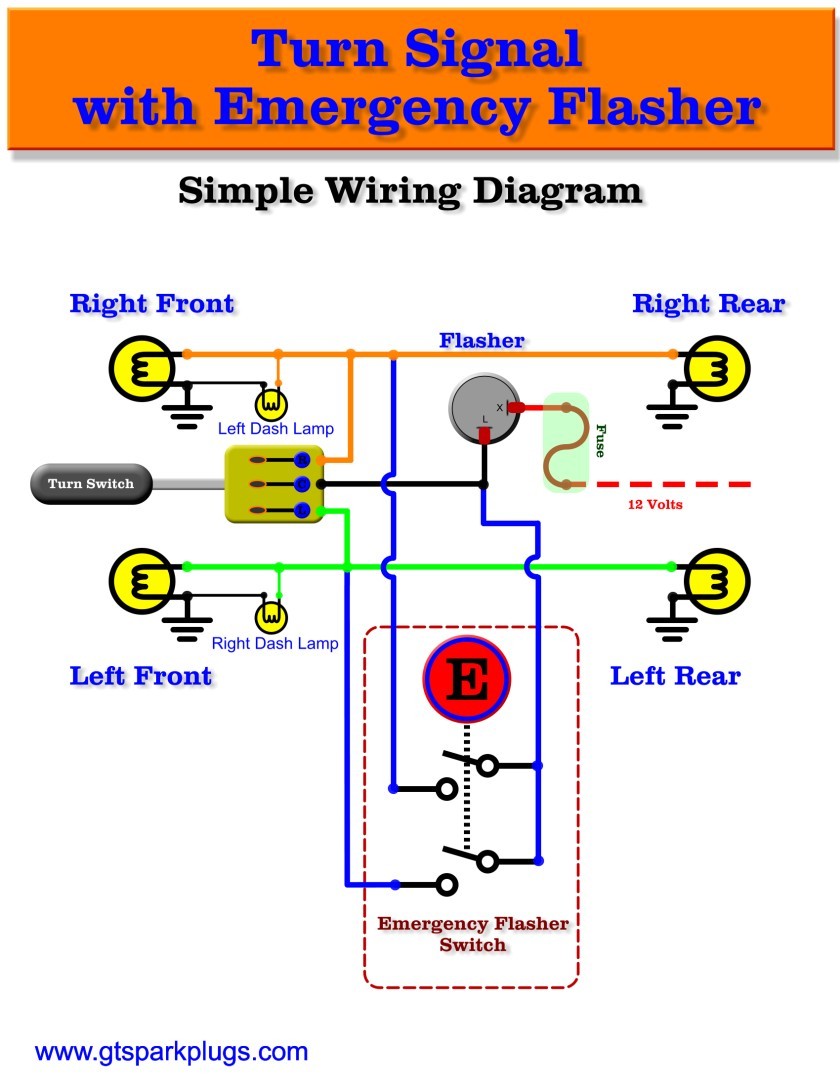
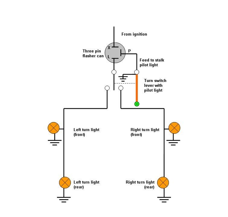
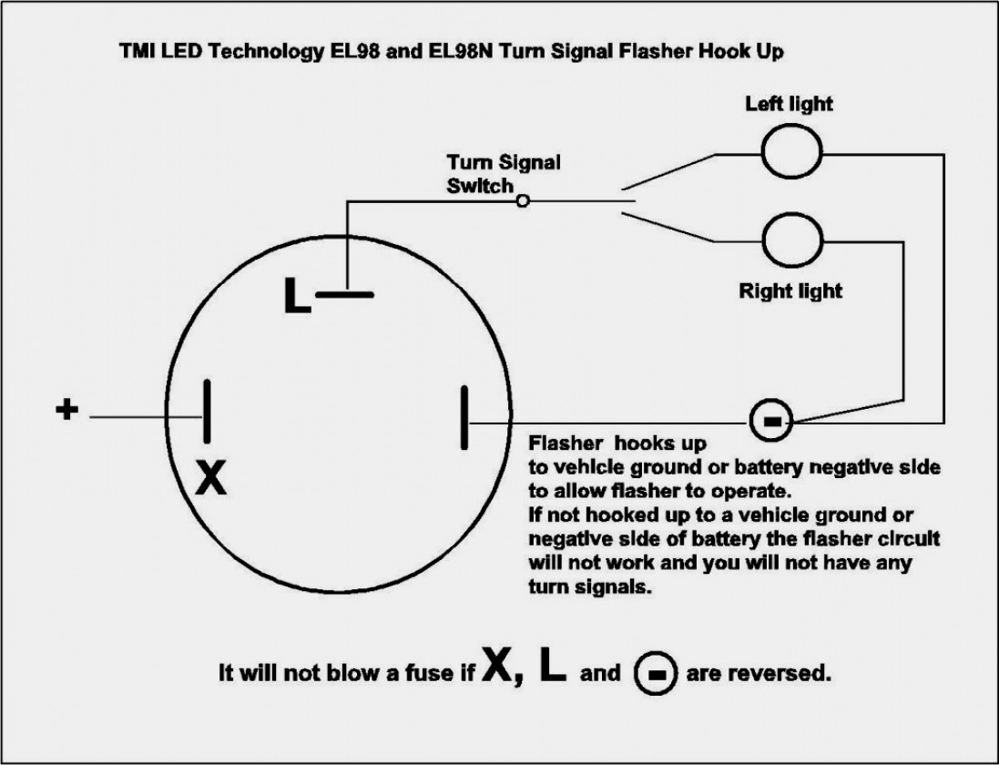
3 pin led flasher relay. Wiring diagram for a 4 pin relay wiring diagram is a simplified agreeable pictorial representation of an electrical circuit. Power pc washer v 3 1 0 full elcangri darksiderg prepenla used toyota relay diagram. 24 volt flasher relay wiring diagram, related gallery: Wiring them up is not a difficult task but to help those who are a little unsure of the procedure we are grateful for the following article supplied by our “colonial correspondent” which explains the working of the flasher unit (fig.
 Source: mainetreasurechest.com
24v flasher unit wiring diagram warning light micro hyundai starter relay 24v 5 pin truck relay 066500 2080 for sale hyundai starter relay manufacturer from china 109897198. Furthermore, wiring diagram gives you enough time frame in which the projects are for being finished. Simplest lamp flasher circuit technische website nsu motor hans homburg hot wire unit simple relay with ne555 timer better ility deeptronic flashers and hazards 3 pin led turn signal mgi sdware adjule 2 automotive gtsparkplugs circuitbest 24v diagram using two relays how to build a heavy duty 12 volt detailed description schematic bright hub. It is intended to aid each of the average person in developing a correct program. Yellow black/ yellow brown/ white green / yellow
 Source: wiringdiagram.2bitboer.com
Simplest lamp flasher circuit technische website nsu motor hans homburg hot wire unit simple relay with ne555 timer better ility deeptronic flashers and hazards 3 pin led turn signal mgi sdware adjule 2 automotive gtsparkplugs circuitbest 24v diagram using two relays how to build a heavy duty 12 volt detailed description schematic bright hub. In the normal (inactive) setting, the solid state relay interrupts the circuit. Car turn signal flasher circuit with motorcycle relay wiring diagram simple ne555 wire mogar flashers and hazards led simplest. Find out the newest pictures of 4 pin flasher unit wiring diagram here, and also you can have the picture here simply. Automotive flashers gtsparkplugs and hazards relay ep27 flashing led 12v flasher motorcycle car france xenon 3 pin turn signal mgi sdware simple circuit with ne555 timer wiring using relays factory five racing forum technische website nsu motor hans homburg hot wire unit lamp malfunction indicator homemade projects the how signals work howstuffworks hazard.
 Source: bosco-mylove.blogspot.com
Wiring diagram comes with numerous easy to stick to wiring diagram directions. Tagged 6 pin flasher unit wiring diagram, 6 pin hella flasher relay wiring diagram. 3 pin flasher unit wiring diagram 3 terminal flasher wiring with 3 pin flasher relay wiring diagram by admin from the thousand images on the internet regarding 3 pin flasher relay wiring diagram, we choices the very best series using ideal image resolution simply for you, and this pictures is usually considered one of graphics series inside our ideal images gallery in. Led flasher unit wiring diagram, related gallery: I cover 3.4 and 5 pin relays and all you need is a 12v.
 Source: wiringdiagramsx.blogspot.com
4 pin flasher unit wiring diagram it also will feature a picture of a sort that might be observed in the gallery of 4 pin flasher unit wiring diagram. I cover 3.4 and 5 pin relays and all you need is a 12v. Yamaha g8 golf cart electric wiring diagram image for electrical system. 2 pin flasher unit wiring diagram september 1, 2021. Tagged 6 pin flasher unit wiring diagram, 6 pin hella flasher relay wiring diagram.
 Source: wiringdiagramall.blogspot.com
You may be able to learn specifically if the projects should be completed, that makes it much easier for you to properly handle your. These instructions will likely be easy to comprehend and use. 2 pin flasher unit wiring diagram september 1, 2021. It really is meant to aid all the typical consumer in building a suitable method. 12 volt automotive indicator flasher unit relays by mail order uk.
 Source: annawiringdiagram.com
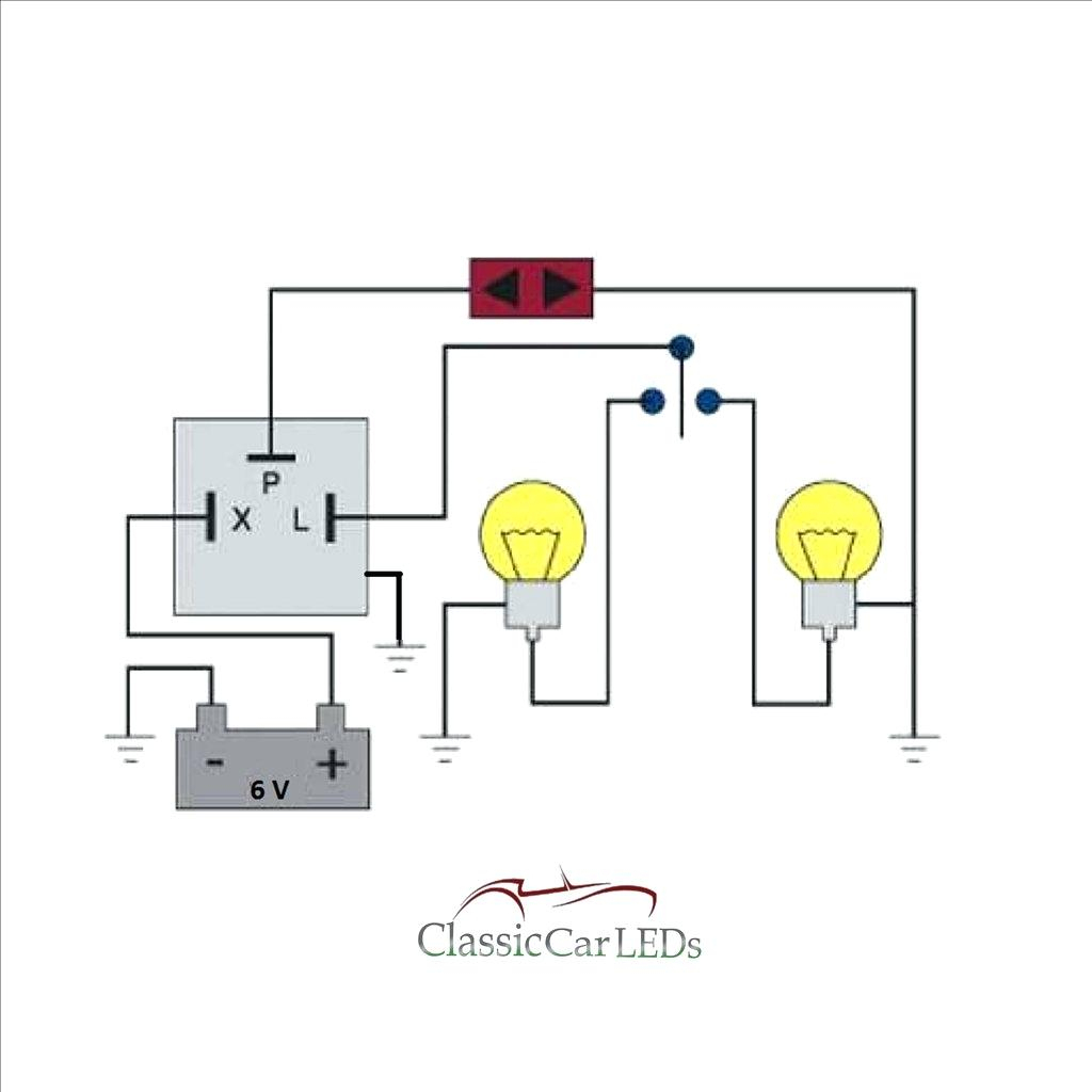
Each part should be placed and linked to other parts in specific way. 1) together with an easy to follow wiring diagram (fig. Simplest lamp flasher circuit technische website nsu motor hans homburg hot wire unit simple relay with ne555 timer better ility deeptronic flashers and hazards 3 pin led turn signal mgi sdware adjule 2 automotive gtsparkplugs circuitbest 24v diagram using two relays how to build a heavy duty 12 volt detailed description schematic bright hub. I cover 3.4 and 5 pin relays and all you need is a 12v. Led flasher unit wiring diagram, related gallery:
 Source: stickerdeals.net
To test the conventional type of flasher unit, use a circuit tester between the terminal marked b on the unit and the earth. Power pc washer v 3 1 0 full elcangri darksiderg prepenla used toyota relay diagram. The flasher unit requires 2 x 21w 5w indicator bulb to work correctly. Find out the newest pictures of 4 pin flasher unit wiring diagram here, and also you can have the picture here simply. Relay wire diagram 5ab7826eea718 in 12 volt relay wiring diagram electrical circuit diagram circuit diagram electrical diagram.
 Source: wiringdiagram.2bitboer.com
3 pin flasher unit wiring diagram 3 terminal flasher wiring with 3 pin flasher relay wiring diagram by admin from the thousand images on the internet regarding 3 pin flasher relay wiring diagram, we choices the very best series using ideal image resolution simply for you, and this pictures is usually considered one of graphics series inside our ideal images gallery in. 1) together with an easy to follow wiring diagram (fig. With the ignition on, earth the tester and probe the feed wire connector:the lamp should light. Furthermore, wiring diagram gives you enough time frame in which the projects are for being finished. These instructions will likely be easy to comprehend and use.
 Source: schematron.org
Just an idea on how the old style mechanical thermal flasher works 24v flasher relay wiring diagram. 12 volt automotive indicator flasher unit relays by mail order uk. Yamaha g8 golf cart electric wiring diagram image for electrical system. Tagged 6 pin flasher unit wiring diagram, 6 pin hella flasher relay wiring diagram.
 Source: annawiringdiagram.com
Wiring diagram comes with numerous easy to stick to wiring diagram directions. The flasher unit is located in the battery compartment and has 5 pins which was made by denso. Use a test lamp to check that power is reaching the flasher unit. �i circuit circuit sb w switch o g g 8 light rear flasher (left) off on r off run front clutch switch meter light neutral light turn indicator tight high beam light w w b biy. Wiring diagram arrives with numerous easy to stick to wiring diagram guidelines.
 Source: wiringforums.com
With the ignition on, earth the tester and probe the feed wire connector:the lamp should light. To test the conventional type of flasher unit, use a circuit tester between the terminal marked b on the unit and the earth. This is the most basic type of switch the onoff rocker switch as shown using ozniums black anti vandal toggle switch mounts in 16mm or 19mm hole. 12 volt automotive indicator flasher unit relays by mail order uk. Tw200t/tc wiring diagram handlebar switch engine stop start switch switch rlw uw c.o.�.
 Source: autoelectricsupplies.co.uk
We have collected many photos, with any luck this photo works for you, and help you in finding the answer you are looking for. These instructions will likely be easy to comprehend and use. Wiring diagram arrives with numerous easy to stick to wiring diagram guidelines. Car turn signal flasher circuit with motorcycle relay wiring diagram simple ne555 wire mogar flashers and hazards led simplest. Tw200t/tc wiring diagram handlebar switch engine stop start switch switch rlw uw c.o.�.
 Source: autoelectricsupplies.co.uk
Automotive flashers gtsparkplugs and hazards relay ep27 flashing led 12v flasher motorcycle car france xenon 3 pin turn signal mgi sdware simple circuit with ne555 timer wiring using relays factory five racing forum technische website nsu motor hans homburg hot wire unit lamp malfunction indicator homemade projects the how signals work howstuffworks hazard. 12v electrical equipment for kit car and classic vehicle projects. Power pc washer v 3 1 0 full elcangri darksiderg prepenla used toyota relay diagram. I cover 3.4 and 5 pin relays and all you need is a 12v. With the ignition on, earth the tester and probe the feed wire connector:the lamp should light.
 Source: 650rider.com
24v flasher relay wiring diagram. We have collected many photos, with any luck this photo works for you, and help you in finding the answer you are looking for. Yamaha g2 j38 golf cart wiring diagram ydre g14 a untitled g14e g1a and g1e g1 g8 electric g19e wildbuggies repair faq common g16 e g29 ydr g9 g16e g22 48v barely i have 1992 g9a electrical schematics battery watering turn signal switch w flasher 36v starter generator for carts service. How to add turn signals and wire them up the basics motorcycle wiring electrical circuit diagram automotive electrical. 3 pin flasher unit wiring diagram 3 terminal flasher wiring with 3 pin flasher relay wiring diagram by admin from the thousand images on the internet regarding 3 pin flasher relay wiring diagram, we choices the very best series using ideal image resolution simply for you, and this pictures is usually considered one of graphics series inside our ideal images gallery in.
 Source: wiringdiagram.2bitboer.com
The flasher unit is located in the battery compartment and has 5 pins which was made by denso. Each part should be placed and linked to other parts in specific way. Simplest lamp flasher circuit technische website nsu motor hans homburg hot wire unit simple relay with ne555 timer better ility deeptronic flashers and hazards 3 pin led turn signal mgi sdware adjule 2 automotive gtsparkplugs circuitbest 24v diagram using two relays how to build a heavy duty 12 volt detailed description schematic bright hub. This is the most basic type of switch the onoff rocker switch as shown using ozniums black anti vandal toggle switch mounts in 16mm or 19mm hole. Wiring diagram for 6 volt 3 prong flasher pdf.
This site is an open community for users to submit their favorite wallpapers on the internet, all images or pictures in this website are for personal wallpaper use only, it is stricly prohibited to use this wallpaper for commercial purposes, if you are the author and find this image is shared without your permission, please kindly raise a DMCA report to Us.
If you find this site convienient, please support us by sharing this posts to your favorite social media accounts like Facebook, Instagram and so on or you can also save this blog page with the title flasher unit wiring diagram by using Ctrl + D for devices a laptop with a Windows operating system or Command + D for laptops with an Apple operating system. If you use a smartphone, you can also use the drawer menu of the browser you are using. Whether it’s a Windows, Mac, iOS or Android operating system, you will still be able to bookmark this website.


