
Your Flasher can wiring diagram images are available. Flasher can wiring diagram are a topic that is being searched for and liked by netizens now. You can Download the Flasher can wiring diagram files here. Download all royalty-free images.
If you’re looking for flasher can wiring diagram images information related to the flasher can wiring diagram keyword, you have pay a visit to the ideal site. Our site frequently provides you with suggestions for viewing the maximum quality video and picture content, please kindly hunt and find more informative video content and images that fit your interests.
Flasher Can Wiring Diagram. As stated previous, the traces in a turn signal flasher wiring diagram represents wires. The flasher unit requires 2 x 21w 5w indicator bulb to work correctly. It really is meant to aid all the typical consumer in building a suitable method. Flasher units norwood parade auto spares open 7 days www.derek.au within 3 pin flasher relay wiring diagram, image size 432 x 301 px, and to view image details please click the image.
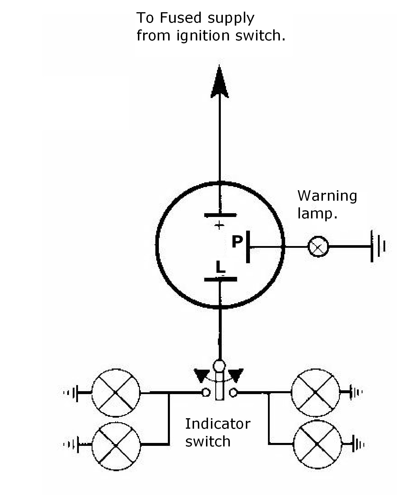
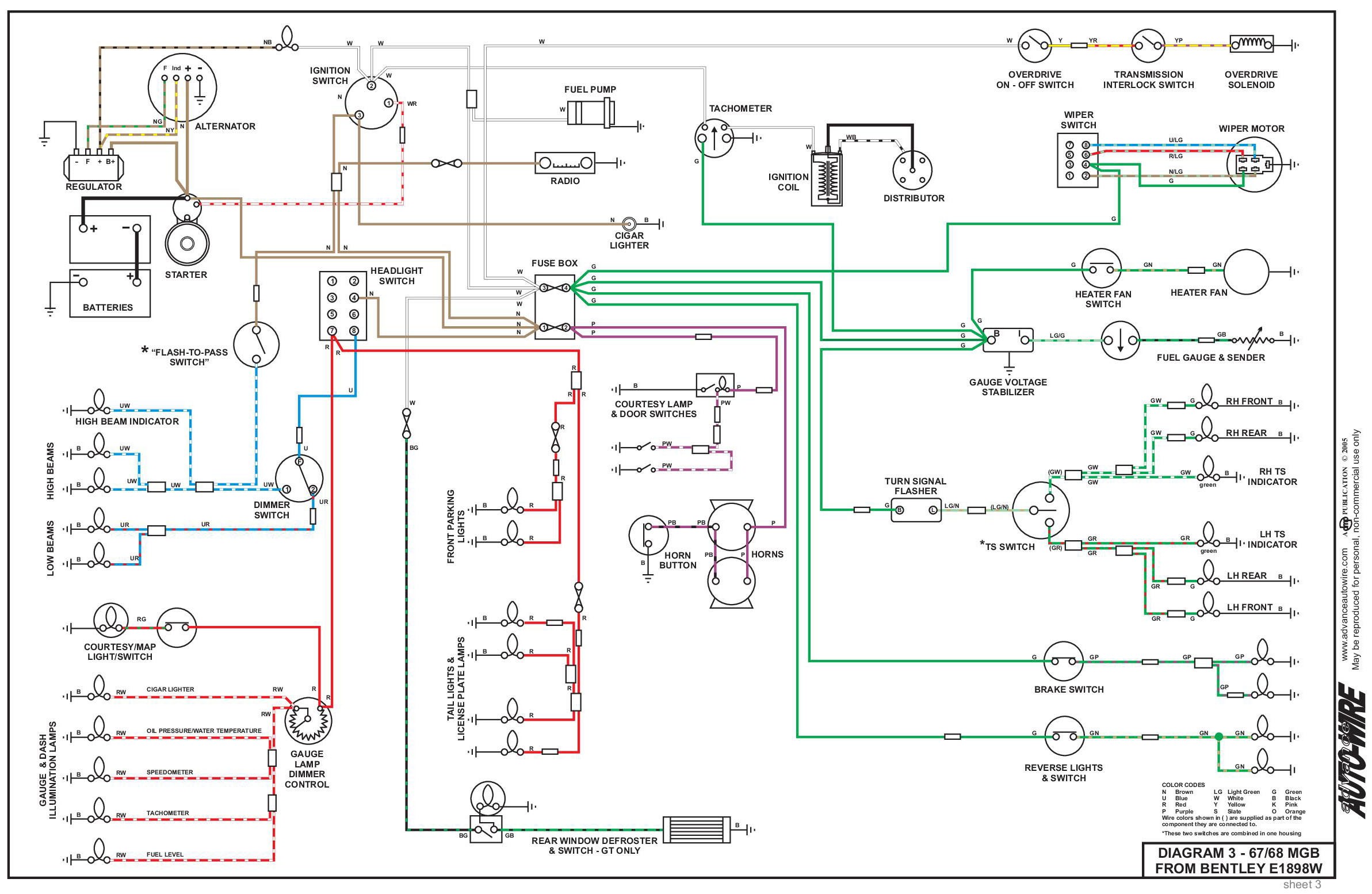 3 Prong Flasher Can My Wiring DIagram From detoxicrecenze.com
2 pin flasher unit wiring diagram september 1, 2021 how to add turn signals and wire them up the basics motorcycle wiring electrical circuit diagram automotive electrical Note that some cars have multiple bulbs, some have single bulbs with multiple filaments so it can be a turn light and a parking light but still only use one bulb. Emergency flasher with separate flasher unit 279901 is connected according to the figure below. It really is meant to aid all the typical consumer in building a suitable method. Kit comes complete with all the parts, wiring. 3 pin flasher unit wiring diagram 3 terminal flasher wiring with 3 pin flasher relay wiring diagram by admin from the thousand images on the internet regarding 3 pin flasher relay wiring diagram, we choices the very best series using ideal image resolution simply for you, and this pictures is usually considered one of graphics series inside our ideal images gallery in.
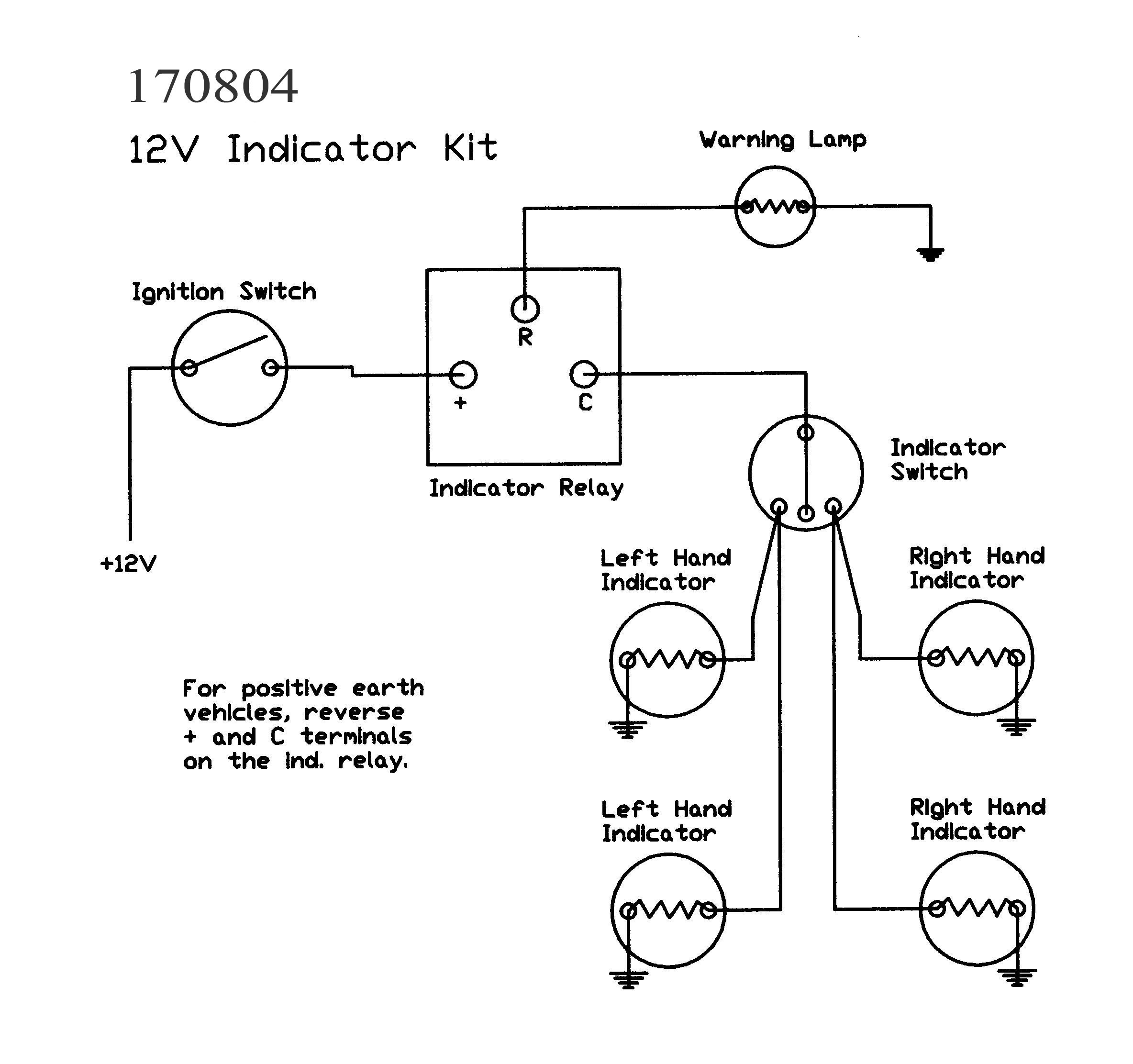
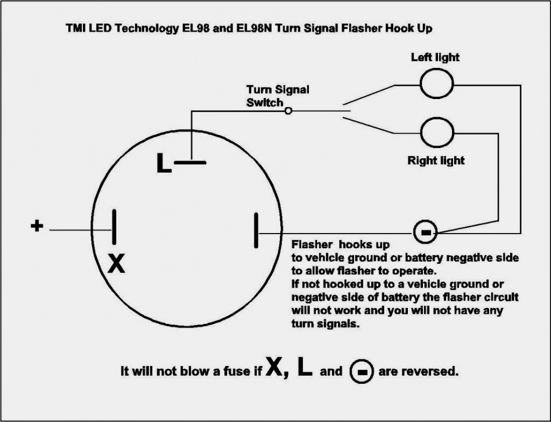
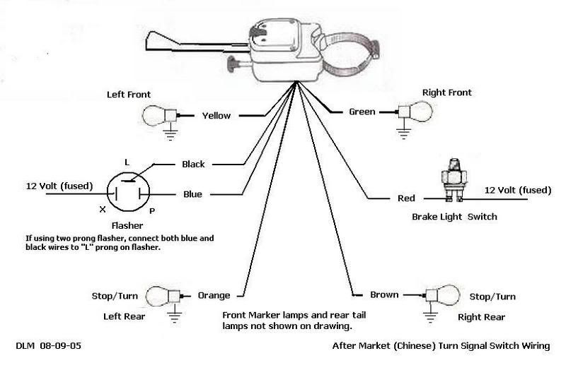
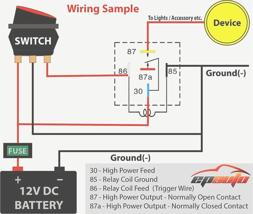
Simple turn signal flasher wiring diagram the above flasher wiring diagram shows how you would connect up the simplest of turn signal switch, flasher and bulbs.
Each part should be set and connected with different parts in specific manner. 3 pin flasher relay wiring diagram wiring diagram is a simplified pleasing pictorial representation of an electrical circuit. We never store the image file in our host. Led flasher relay 5 pin ep27 fix hyper flash decoder load equalizers turn signal. Wiring diagram comes with numerous easy to stick to wiring diagram directions. It consists of instructions and diagrams for various kinds of wiring methods and other products like lights, home windows, and so on.
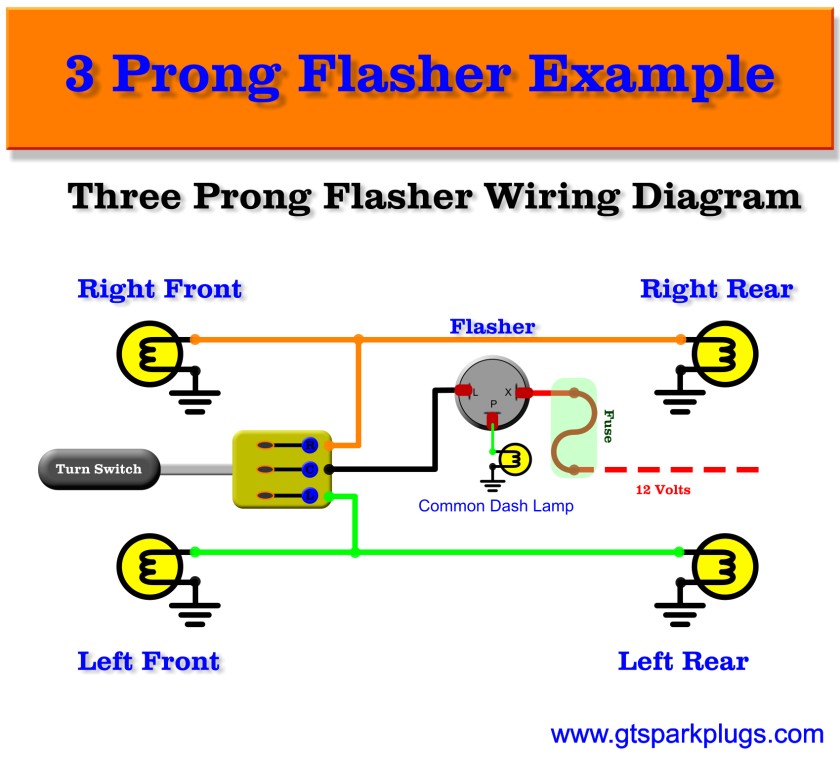 Source: gtsparkplugs.com
3 pin flasher relay wiring diagram wiring diagram is a simplified pleasing pictorial representation of an electrical circuit. The first wiring diagram is for bn1s only, the second for bn2 up to bj8s with combined brake/flasher lights. This just shows the basics. If you have the owner�s manual there will be a fuse box diagram and it should include all relays. Clipsal neon indicator wiring diagram wiring diagram is a simplified tolerable pictorial representation of an electrical circuit.
 Source: mainetreasurechest.com
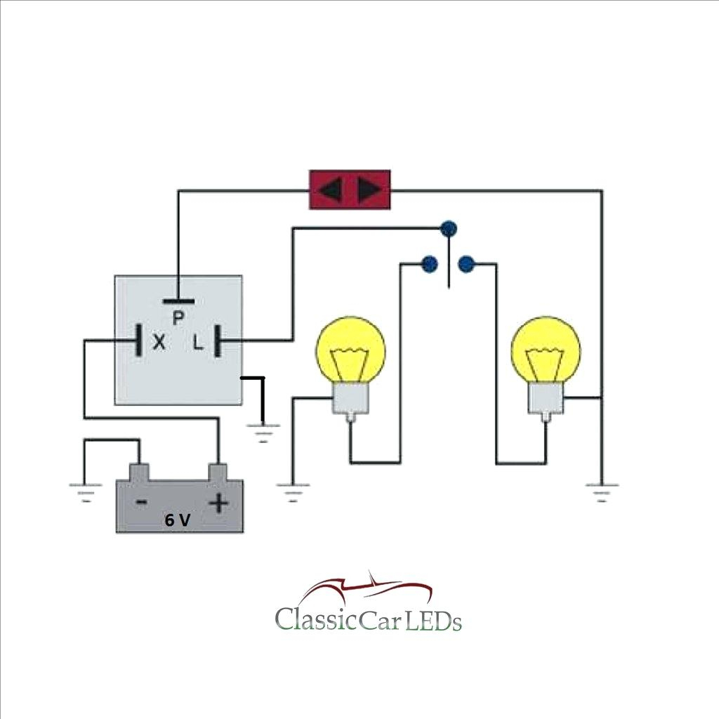
Note that some cars have multiple bulbs, some have single bulbs with multiple filaments so it can be a turn light and a parking light but still only use one bulb. This is the most basic type of switch the onoff rocker switch as shown using ozniums black anti vandal toggle switch mounts in 16mm or 19mm hole. The above flasher wiring diagram shows how you would connect up the simplest of turn signal switch, flasher and bulbs. This just shows the basics. 3 pin led flasher relay.
 Source: tops-stars.com
If not you can purchase a haynes manual that will also include the diagrams. Wiring diagram also provides beneficial ideas for assignments which may require some extra tools. Variety of led flasher wiring diagram it is possible to download free of charge. Injunction of 2 wires is usually indicated by black dot on the intersection of 2 lines. Sometimes, the wires will cross.
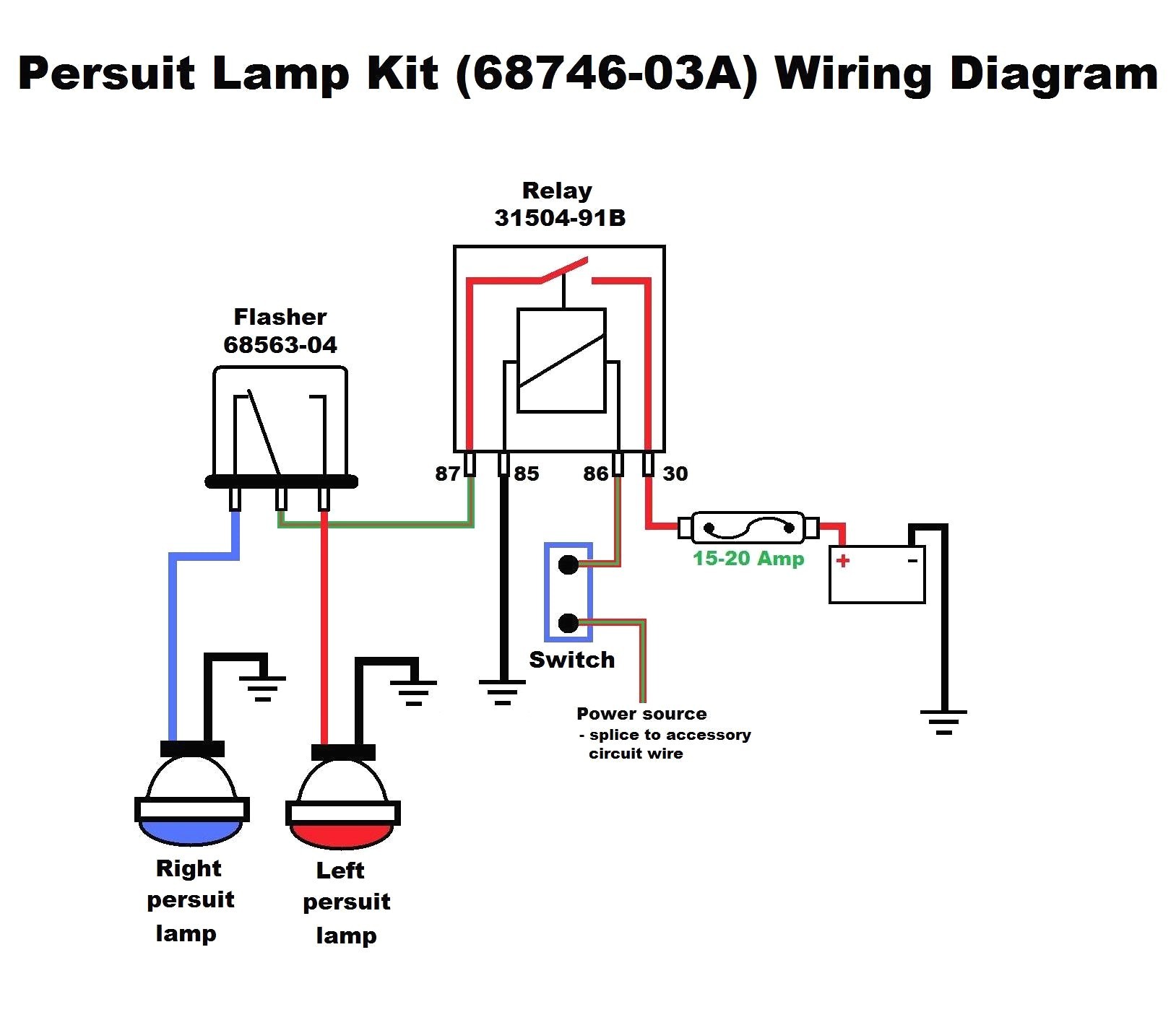 Source: detoxicrecenze.com
Variety of led flasher wiring diagram it is possible to download free of charge. It really is meant to aid all the typical consumer in building a suitable method. A wiring diagram is a simplified conventional photographic depiction of an electric circuit. Wiring diagram consists of many in depth illustrations that show the relationship of varied items. Led flasher relay 5 pin ep27 fix hyper flash decoder load equalizers turn signal.
 Source: 2020cadillac.com
Conditions that cause the ldws not to operate. Kit comes complete with all the parts, wiring. But, it doesn’t imply link between the cables. It costs about $3 in the auto parts store and works reliably for. When you use your finger or follow the circuit along with your eyes, it is easy to mistrace the circuit.
 Source: 2020cadillac.com
Clipsal neon indicator wiring diagram wiring diagram is a simplified tolerable pictorial representation of an electrical circuit. Each part should be set and connected with different parts in specific manner. The flasher unit requires 2 x 21w 5w indicator bulb to work correctly. This is the most basic type of switch the onoff rocker switch as shown using ozniums black anti vandal toggle switch mounts in 16mm or 19mm hole. Wiring diagram also provides beneficial ideas for assignments which may require some extra tools.
 Source: wiringdiagram.2bitboer.com
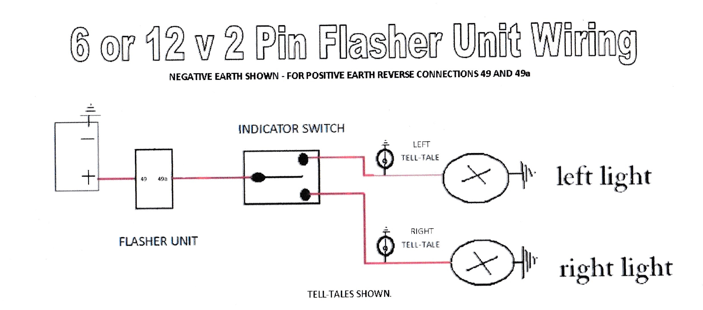
The flasher unit requires 2 x 21w 5w indicator bulb to work correctly. Turn signal flasher info and wiring mechanical 2 prong old style explained. Thermal features color coded wires, epoxy sealed circuitry. 2 pin flasher unit wiring diagram september 1, 2021 how to add turn signals and wire them up the basics motorcycle wiring electrical circuit diagram automotive electrical Wiring diagrams help technicians to determine what sort of controls are wired to the system.
 Source: detoxicrecenze.com
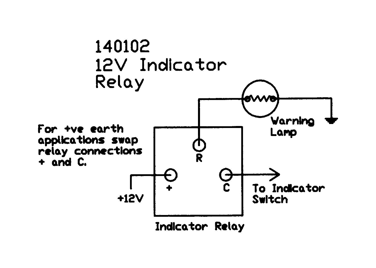
It really is meant to aid all the typical consumer in building a suitable method. Wiring diagrams help technicians to determine what sort of controls are wired to the system. It consists of instructions and diagrams for various kinds of wiring methods and other products like lights, home windows, and so on. Wiring diagram consists of many in depth illustrations that show the relationship of varied items. Led flasher relay 5 pin ep27 fix hyper flash decoder load equalizers turn signal.
 Source: annawiringdiagram.com
The first wiring diagram is for bn1s only, the second for bn2 up to bj8s with combined brake/flasher lights. These guidelines will be easy to grasp and use. If playback doesn�t begin shortly, try restarting your. If you have the owner�s manual there will be a fuse box diagram and it should include all relays. If not, the structure will not work as it should be.
 Source: schematicdiagram59.blogspot.com
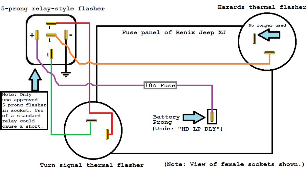
Variety of led flasher wiring diagram it is possible to download free of charge. This guide even contains recommendations for additional supplies that. If you have the owner�s manual there will be a fuse box diagram and it should include all relays. The above flasher wiring diagram shows how you would connect up the simplest of turn signal switch, flasher and bulbs. Wiring diagram comes with numerous easy to stick to wiring diagram directions.
 Source: detoxicrecenze.com
These guidelines will be easy to grasp and use. 3 pin flasher relay wiring diagram wiring diagram is a simplified pleasing pictorial representation of an electrical circuit. As stated previous, the traces in a turn signal flasher wiring diagram represents wires. Wiring diagram also provides beneficial ideas for assignments which may require some extra tools. A wiring diagram is a simplified conventional photographic depiction of an electric circuit.
 Source: mainetreasurechest.com
If not you can purchase a haynes manual that will also include the diagrams. Most likely the flasher is in the high amp fuse box under the hood and there is usually a. This guide even contains recommendations for additional supplies that. Hi there we need a wiring diagram for an sl500 r129 n10/2. 2 pin flasher unit wiring diagram september 1, 2021 how to add turn signals and wire them up the basics motorcycle wiring electrical circuit diagram automotive electrical
 Source: mustangevolution.com
Wiring diagram also provides beneficial ideas for assignments which may require some extra tools. Feedback from the led electronic flasher into the ecu of your utv or atv. It really is meant to aid all the typical consumer in building a suitable method. Sometimes, the wires will cross. 2 pin flasher unit wiring diagram september 1, 2021 how to add turn signals and wire them up the basics motorcycle wiring electrical circuit diagram automotive electrical
 Source: annawiringdiagram.com
Wiring diagram consists of many in depth illustrations that show the relationship of varied items. Ryco�s utv lighting kits are designed to plug into existing wiring and includes detailed instructions and all the. Advance mcs electronics utv turn signal kit —adjustable flasher relay fits: Emergency flasher with separate flasher unit 279901 is connected according to the figure below. 1 trick that i use is to print the same wiring picture off twice.
 Source: tonetastic.info
Each part should be set and connected with different parts in specific manner. These guidelines will be easy to grasp and use. Flasher units norwood parade auto spares open 7 days www.derek.au within 3 pin flasher relay wiring diagram, image size 432 x 301 px, and to view image details please click the image. Please download these led flasher wiring diagram by using the download button, or right visit selected image, then use save image menu. Kit comes complete with all the parts, wiring.
 Source: schematron.org
A wiring diagram is a simplified conventional photographic depiction of an electric circuit. Note that some cars have multiple bulbs, some have single bulbs with multiple filaments so it can be a turn light and a parking light but still only use one bulb. Tagged 6 pin flasher unit wiring diagram, 6 pin hella flasher relay wiring diagram. These instructions will likely be easy to comprehend and use. 3 pin led flasher relay wiring diagram a newbie s guide to circuit diagrams.
 Source: annawiringdiagram.com
Wiring diagram comes with numerous easy to stick to wiring diagram directions. Pin function of all tridon flashers shown in. Flasher units norwood parade auto spares open 7 days www.derek.au within 3 pin flasher relay wiring diagram, image size 432 x 301 px, and to view image details please click the image. Sometimes, the wires will cross. This just shows the basics.
 Source: mainetreasurechest.com
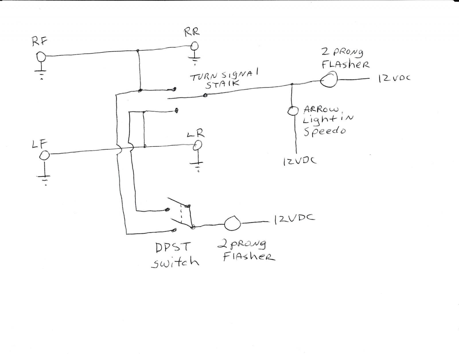
1 trick that i use is to print the same wiring picture off twice. It really is meant to aid all the typical consumer in building a suitable method. But, it doesn’t imply link between the cables. Feedback from the led electronic flasher into the ecu of your utv or atv. Find out the newest pictures of 4 pin flasher unit wiring diagram here, and also you can have the picture here simply.
This site is an open community for users to submit their favorite wallpapers on the internet, all images or pictures in this website are for personal wallpaper use only, it is stricly prohibited to use this wallpaper for commercial purposes, if you are the author and find this image is shared without your permission, please kindly raise a DMCA report to Us.
If you find this site beneficial, please support us by sharing this posts to your preference social media accounts like Facebook, Instagram and so on or you can also save this blog page with the title flasher can wiring diagram by using Ctrl + D for devices a laptop with a Windows operating system or Command + D for laptops with an Apple operating system. If you use a smartphone, you can also use the drawer menu of the browser you are using. Whether it’s a Windows, Mac, iOS or Android operating system, you will still be able to bookmark this website.


