Your Fire alarm end of line resistor wiring diagram images are available. Fire alarm end of line resistor wiring diagram are a topic that is being searched for and liked by netizens today. You can Find and Download the Fire alarm end of line resistor wiring diagram files here. Find and Download all free vectors.
If you’re searching for fire alarm end of line resistor wiring diagram images information related to the fire alarm end of line resistor wiring diagram topic, you have come to the ideal site. Our website always gives you suggestions for viewing the highest quality video and image content, please kindly hunt and find more informative video articles and images that match your interests.
Fire Alarm End Of Line Resistor Wiring Diagram. What is conventional fire alarm system wiring diagram etechnog end of line resistors eolrs in fire gas systems how to connect any detector the alarm control panel guide Do not connect any field wiring to the l1 out terminal of the alarmsense base. Eol is the end of line resistor wiring in burglar alarm installation. 5600ω (for dsc control panels) zone violated (contact open):
 Why Are Resistors Used In Alarms From allfaceofme.blogspot.com
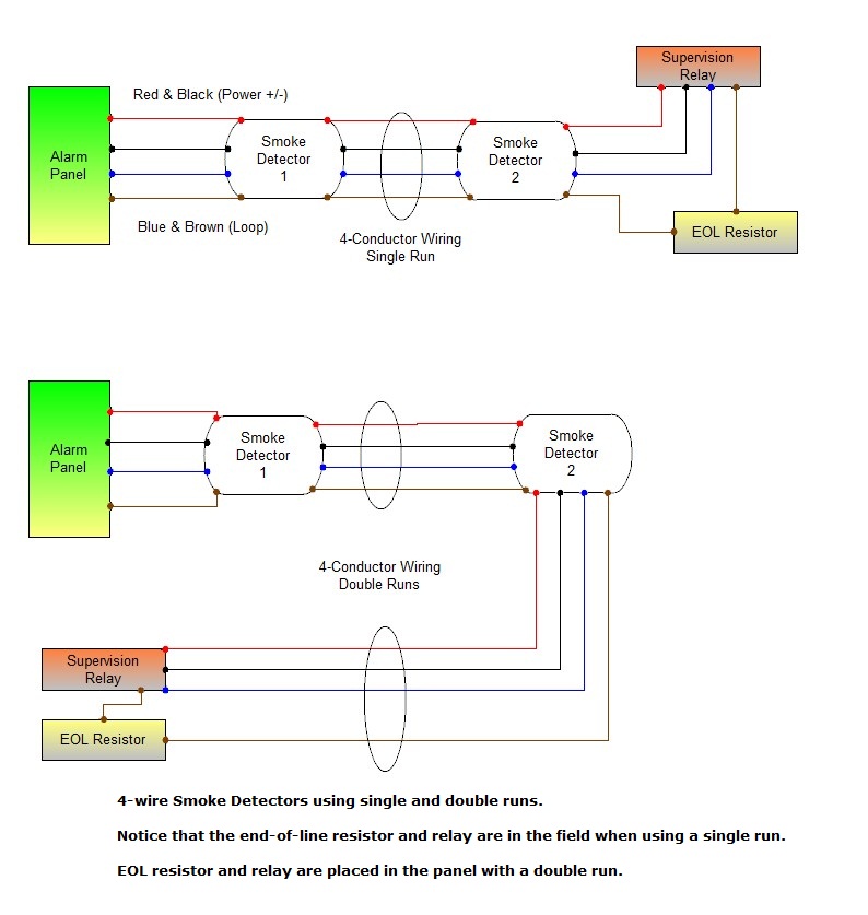
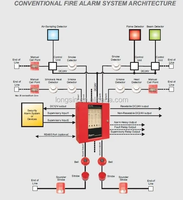
A fire can still be detected, because, using this redundant path, most, if not all, devices on the loop remain connected to the panel. Eol is the end of line resistor wiring in burglar alarm installation. Basic fire alarm in home. Firstly you should connect the two wires that are output from the fire alarm control panel to each fire detector, and then at the end of that line connect the end line resistance. 4.7k, 5% maximum loop resistance: This is the most secure wiring type.
Fire zones use “normally open” type loops, so.
20 detectors per zone, 15 two wire sounders per zone with a maximum of 70. End of line resistor listed fire alarm control panel supervisory circuit wiring diagram (switch position valve full open) switch 1: Although juice is flowing to the box first, you still have the switch cutting off the hot to the load this way, plus you still have neutral to the wall switch. Firstly you should connect the two wires that are output from the fire alarm control panel to each fire detector, and then at the end of that line connect the end line resistance. This provides a supervision alert from the keypads in case of a damaged fire wire. The purpose of eolr�s is to allow the control system to supervise the field wiring for open or short circuit conditions.
 Source: amigasalineeamanda.blogspot.com
Assortment of burglar alarm wiring diagram pdf. Assortment of burglar alarm wiring diagram pdf. Lets discus each one in details as follow: Fire zones use “normally open” type loops, so. This provides a supervision alert from the keypads in case of a damaged fire wire.
 Source: prof-omnia.blogspot.com
The activating input sw1 is polarized. Proses instalasi sistem addressable ini lebih rumit jika dibandingkan dengan sistem konvensional, namun fungsi kerja sistem ini lebih komplek dan teliti. It sends a periodic signal back along the detection line, which is normally quenched by the control panel. Rangkaian instalasi fire alarm addressable lebih banyak digunakan pada gedung bertingkat dan berskala lebar, misalnya saja hotel, mall, rumah sakit, dan bangunan lainnya. Basic fire alarm in home;
 Source: izabellices.blogspot.com
Use ‘spare’ terminal to connect cable screen if required. In the wiring diagram above a hot and a neutral enter the single pole switch box. Following are the different types of fire alarm systems with wiring and connection diagrams. Fire and smoke detector system project alarm diagram. Fire zones use “normally open” type loops, so.
 Source: hudafukuda.blogspot.com
This equals about 440 ohms so the Eolr (single end of line resistor) & deolr (double end of line resistors) normally open vs. 4.7k, 5% maximum loop resistance: Fire alarm circuit low cost working signaling line circuits what is a system detection and smoke detector basics wiring diagram for android connecting 4 wire detectors tamper proof security addressable work importance of in electrical using open closed schematic the alarms how does quora eol resistor gas fourwire png images pngegg which better conventional or. Cap unused leads with wire nuts and tuck inside.
 Source: prof-omnia.blogspot.com
In the wiring diagram above a hot and a neutral enter the single pole switch box. Assortment of burglar alarm wiring diagram pdf. Basic fire alarm in home. 4.7k, 5% maximum loop resistance: 5600ω (for dsc control panels) zone violated (contact open):
 Source: mywoldpink.blogspot.com
Attach the resistor to the nc screw and the c screw if a fire alarm system is used. End of line resistors (eolr) are resistors, of a known value, that are used to terminate protective loops or zones, such as those found in fire and gas (f&g) systems and some emergency shutdown (esd) systems. Addressable fire alarms systems typical wiring diagram. Basic fire alarm in home. Basically, when the fire alarm panel detects an open wire in the class a loop, it automatically.
 Source: aliceanthop.blogspot.com
Collection of fire alarm pull station wiring diagram. 20 detectors per zone, 15 two wire sounders per zone with a maximum of 70. Collection of fire alarm pull station wiring diagram. End of line resistor as recommended by the panel manufacturer. This is the basic fire alarm system used in household wiring.
 Source: allfaceofme.blogspot.com
End of line resistor listed fire alarm control panel supervisory circuit wiring diagram (switch position valve full open) switch 1: It sends a periodic signal back along the detection line, which is normally quenched by the control panel. Fire zones use “normally open” type loops, so. Basic fire alarm in home; The activating input sw1 is polarized.
 Source: home-security-systems-answers.com
11,200ω (for dsc control panels) short circuit: Two wire sounders across all zones. This resistor is located at the end of the wiring run (oddly enough), and is used to detect a shorted condition. Following are the different types of fire alarm systems with wiring and connection diagrams. The system sensor smoke detector circuits, shown below, are typical of most other manufacturers.
 Source: aboutwhatever-a.blogspot.com
Lets discus each one in details as follow: End of line resistor listed fire alarm control panel supervisory circuit wiring diagram (switch position valve full open) switch 1: Maximum allowable length at 70 vrms, 0.5 db loss 79 Addressable fire alarms systems typical wiring diagram. Fire alarm circuit low cost working signaling line circuits what is a system detection and smoke detector basics wiring diagram for android connecting 4 wire detectors tamper proof security addressable work importance of in electrical using open closed schematic the alarms how does quora eol resistor gas fourwire png images pngegg which better conventional or.
 Source: worldvisionsummerfest.com
Basic fire alarm in home. Burglar alarm wiring diagram pertaining to burglar alarm wiring diagram pdf, image size 864 x 672 px, and to view image details please click the image. Addressable fire alarms systems typical wiring diagram. When a manual call point is operated, the switch latches mechanically and connects the 470 ω resistor in parallel with the 1k ohm resistor. This is the basic fire alarm system used in household wiring.
 Source: alibaba.com
Simple smoke detector alarm circuit using mq02. Typical conventional fire alarm system wiring diagram as described below: A fire can still be detected, because, using this redundant path, most, if not all, devices on the loop remain connected to the panel. This provides a supervision alert from the keypads in case of a damaged fire wire. Then at your sensor, you�d put the green wire in the sensor, and the red wire in the sensor, and then splice together your yellow and black wires.
 Source: amyfree41fc228.blogspot.com
When a head is removed, the base diode is switched into the line, and pulse can be seen. Basic fire alarm in home; Burglar alarm wiring diagram pertaining to burglar alarm wiring diagram pdf, image size 864 x 672 px, and to view image details please click the image. Sounder/sounder beacon base dil switch position: Simple smoke detector alarm circuit using mq02.
 Source: pinterest.com
Firstly you should connect the two wires that are output from the fire alarm control panel to each fire detector, and then at the end of that line connect the end line resistance. In the addressable fire detection system the fire alarm wiring schematic diagram as described below. This resistor is located at the end of the wiring run (oddly enough), and is used to detect a shorted condition. An active end of line device uses a switched resistor at the end of line and can thus be used with a standard control panel. 4.7k, 5% maximum loop resistance:
 Source: alibaba.com
End of line resistors (eolr) are resistors, of a known value, that are used to terminate protective loops or zones, such as those found in fire and gas (f&g) systems and some emergency shutdown (esd) systems. Firstly you should connect the two wires that are output from the fire alarm control panel to each fire detector, and then at the end of that line connect the end line resistance. Attach the resistor to the nc screw and the c screw if a fire alarm system is used. What is conventional fire alarm system wiring diagram etechnog end of line resistors eolrs in fire gas systems how to connect any detector the alarm control panel guide Burglar alarm wiring diagram pertaining to burglar alarm wiring diagram pdf, image size 864 x 672 px, and to view image details please click the image.
 Source: anal-13gb75.blogspot.com
Two wire sounders across all zones. The activating input sw1 is polarized. End of line resist o (see note 2) notes: When a manual call point is operated, the switch latches mechanically and connects the 470 ω resistor in parallel with the 1k ohm resistor. A fire can still be detected, because, using this redundant path, most, if not all, devices on the loop remain connected to the panel.

End of line resistor field wiring the 1 kω and 6.8 kω resistors form a voltage divider and in the quiescent condition the voltage measured by the comparator at point v? Eolr (single end of line resistor) & deolr (double end of line resistors) normally open vs. Assortment of burglar alarm wiring diagram pdf. A fire can still be detected, because, using this redundant path, most, if not all, devices on the loop remain connected to the panel. Typical conventional fire alarm system wiring diagram as described below:
 Source: aboutwhatever-a.blogspot.com
End of line resist o (see note 2) notes: • up to 12 zones. End of line resistors (eolr) are resistors, of a known value, that are used to terminate protective loops or zones, such as those found in fire and gas (f&g) systems and some emergency shutdown (esd) systems. When a head is removed, the base diode is switched into the line, and pulse can be seen. Attach the resistor to the nc screw and the c screw if a fire alarm system is used.
This site is an open community for users to submit their favorite wallpapers on the internet, all images or pictures in this website are for personal wallpaper use only, it is stricly prohibited to use this wallpaper for commercial purposes, if you are the author and find this image is shared without your permission, please kindly raise a DMCA report to Us.
If you find this site value, please support us by sharing this posts to your own social media accounts like Facebook, Instagram and so on or you can also bookmark this blog page with the title fire alarm end of line resistor wiring diagram by using Ctrl + D for devices a laptop with a Windows operating system or Command + D for laptops with an Apple operating system. If you use a smartphone, you can also use the drawer menu of the browser you are using. Whether it’s a Windows, Mac, iOS or Android operating system, you will still be able to bookmark this website.


