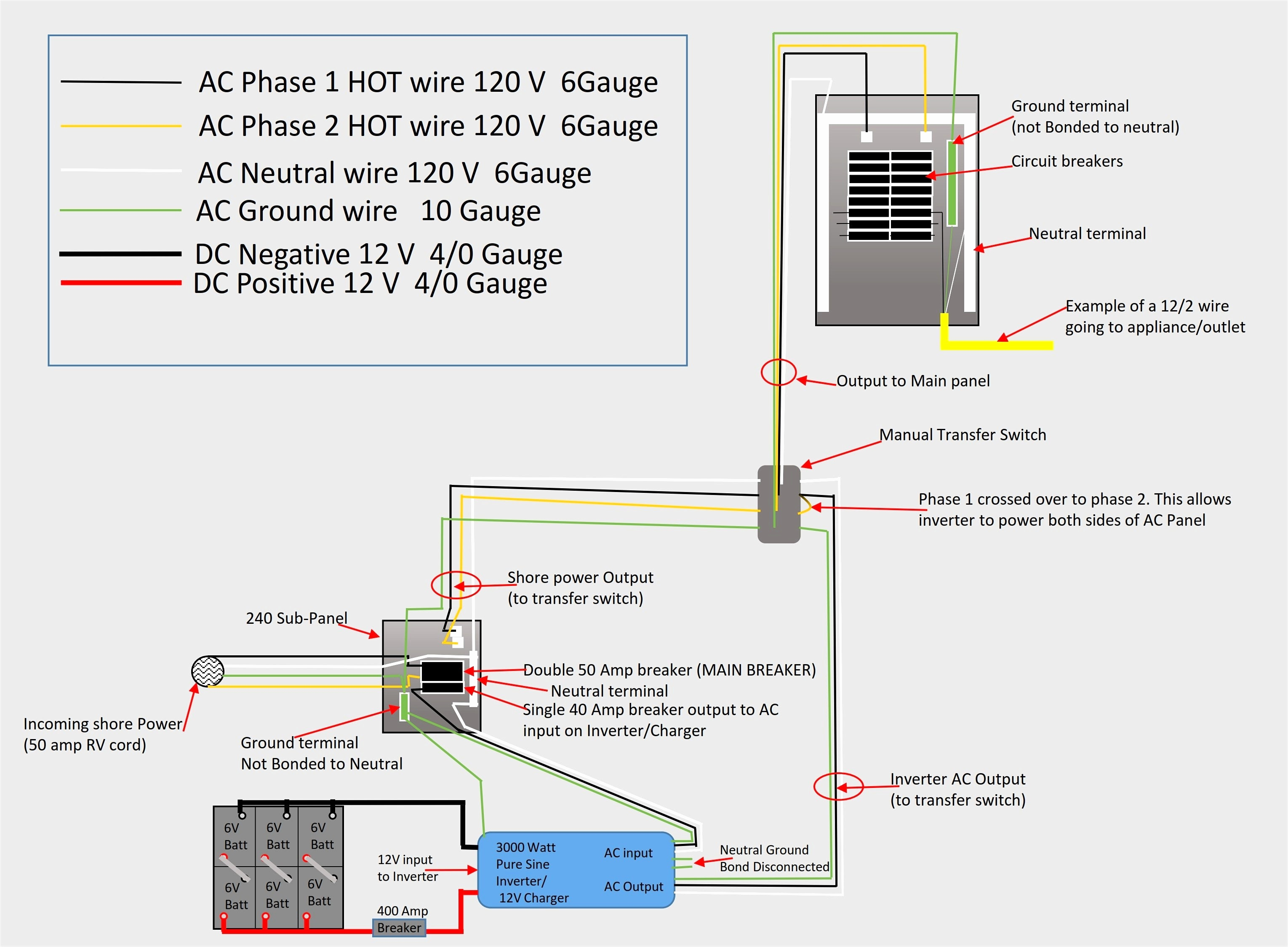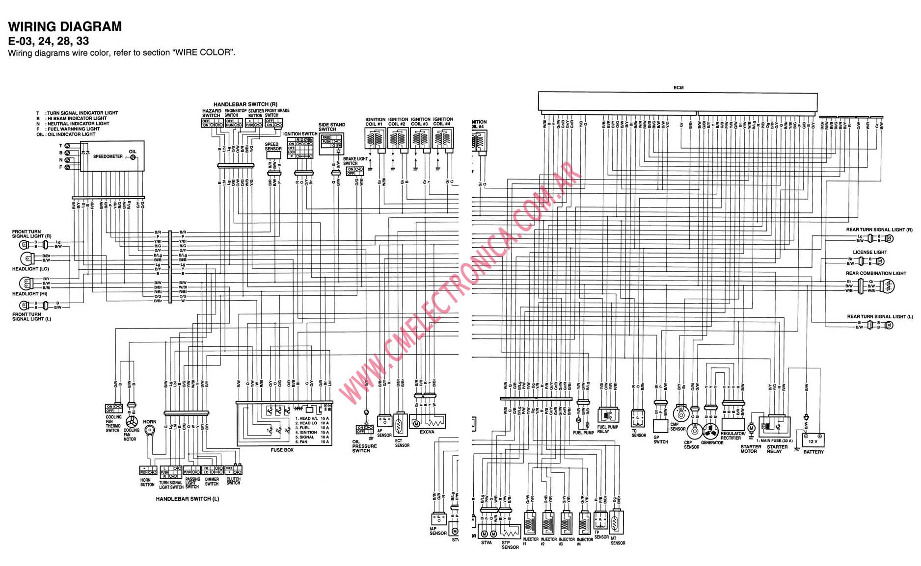
Your Fcu motor wiring diagram images are ready. Fcu motor wiring diagram are a topic that is being searched for and liked by netizens today. You can Find and Download the Fcu motor wiring diagram files here. Get all free images.
If you’re looking for fcu motor wiring diagram pictures information connected with to the fcu motor wiring diagram interest, you have pay a visit to the ideal site. Our site frequently gives you hints for seeing the highest quality video and image content, please kindly search and find more informative video articles and images that fit your interests.
Fcu Motor Wiring Diagram. Electrical wiring connection this is a proposed wiring connection. It may change subject to the chiller unit and must comply with local and national code and regulations. Terminal markings and internal wiring diagrams single phase and polyphase motors meeting nema standards see fig. The available cooling capacity of common packaged rooftop units ranges from 10 kw (3 tons) to 850 kw (241 tons).

Each component ought to be placed and linked to different parts in. Electrical wiring connection this is a proposed wiring connection. As stated earlier the traces in a ford f150 radio wiring harness diagram represents wires. Via the fan�s ecm motor. Ge motor wiring diagram missing [ 1 answers ] hello! • may, 2001 • fan coil unit control applications 5 low voltage options 24 vac fan speed and temperature control4:
Premium color wiring diagrams get premium wiring diagrams that are available for your vehicle that are accessible online right now, purchase full set of complete wiring diagrams so you can have full online access to everything you need including premium wiring diagrams, fuse and component locations, repair information, factory recall information and even tsb�s (technical.
In this post, we have shown how to set up the coil size of a 1 hp 3. Each component ought to be placed and linked to different parts in. They show the relative location of the components. Via the fan�s ecm motor. As you can see the circuit starts and ends at the consumer unit. It may change subject to the chiller unit and must comply with local and national code and regulations.
 Source: wiringdiagramall.blogspot.com
Use the following chart to interpret the type code found on the and control wiring. This procedure works for electric motors that are able to operate with either 110 or 220 volt power by changing a few […] They can be used as a guide when wiring the controller. Each component ought to be placed and linked to different parts in. Motor configured for high voltage.
 Source: wiringdiagramharnessideas.blogspot.com
They show the relative location of the components. Hi my name is anthony i was hoping that i could get from you the wiring diagram for a 2003 ford ranger fx1 the diagrams that i am looking for are the connectors for the multi function switch connectors c202a and c202b what happened is i pulled the connectors off to change the mgs because my turn signals where not working and both the. 2003 ford escape stereo wiring diagram. Terminal markings and internal wiring diagrams single phase and polyphase motors meeting nema standards see fig. Upon a further call for cooling, this cooling coil control valve shall
 Source: rickardair.com
Use the following chart to interpret the type code found on the and control wiring. Wiring diagrams for the various configurations are below. The power schematic diagram for rooftop packaged units is shown in fig.29. As you can see the circuit starts and ends at the consumer unit. It is a series wound motor.
 Source: diychatroom.com
Which are most suitable for the motor. Terminal markings and internal wiring diagrams single phase and polyphase motors meeting nema standards see fig. The air flow rate covers a range from 400 l/s (850 ft3/min) to 37,800 l/s (80,000 ft3/min). Fan coil unit (fcu) fan motor control. Please observe the wiring diagram above.

Change the terminal from close to open structure and the wiring of. 230v / 460v motor configured for 460v ( ) • brake voltage is 460v [1] motor terminal board [4] sr current relay [2] supply leads [5] terminal strip The air flow rate covers a range from 400 l/s (850 ft3/min) to 37,800 l/s (80,000 ft3/min). Electrical wiring connection this is a proposed wiring connection. The power schematic diagram for rooftop packaged units is shown in fig.29.
 Source: mikeadkinsguitar.com
Fcu control diagram not to scale filter supply fan t occupancy sensor. Motor operated valve wiring diagram can be a variety of, can be 2 lines, 3 lines, 4 lines, can also be connected with a feedback signal line, 2 lines can also be with ground wire. Includes 24 vac transformer, 3 fan speed relays and wiring modifications. Electrical wiring connection this is a proposed wiring connection. Online motor wiring diagram schematics.
 Source: alibaba.com
Brake = 460v brake control: This procedure works for electric motors that are able to operate with either 110 or 220 volt power by changing a few […] It goes around the house (or a room) and connects to all the sockets and fused connection units (fcu`s) required to be on the ring main circuit. Fcu control diagram not to scale filter supply fan t occupancy sensor. Change the terminal from close to open structure and the wiring of.
 Source: paktechpoint.com
Terminal markings and internal wiring diagrams single phase and polyphase motors meeting nema standards see fig. Brake voltage matches the high motor voltage. Addition with good insulated noise eliminated material, unit noise is 2~5db(a) lower than the same type unit. 7 zoll android 11 0 für 2005 2008 2009 ford esca. Abb vfd control wiring diagram.
 Source: fjelloghjem.blogspot.com
The power schematic diagram for rooftop packaged units is shown in fig.29. The air flow rate covers a range from 400 l/s (850 ft3/min) to 37,800 l/s (80,000 ft3/min). Motor 3ct to 120 v separate control * ot is a switch that opens when an overtemperature condition exists (type mfo and mgo only) t1 t3 motor 3 2 l2 t2. Controlled environment that is suitable for the selected enclosure. 230v / 460v motor configured for 460v ( ) • brake voltage is 460v [1] motor terminal board [4] sr current relay [2] supply leads [5] terminal strip
 Source: pinterest.com
They show the relative location of the components. Ge motor wiring diagram missing [ 1 answers ] hello! 4 wire motor connection diagram. Change the terminal from close to open structure and the wiring of. Online motor wiring diagram schematics.

Wiring diagrams for the various configurations are below. The air flow rate covers a range from 400 l/s (850 ft3/min) to 37,800 l/s (80,000 ft3/min). Baldor single phase 230v motor wiring diagram. • may, 2001 • fan coil unit control applications 5 low voltage options 24 vac fan speed and temperature control4: Please observe the wiring diagram above.
 Source: wiringideas.blogspot.com
The fan relay board assembly (frbii) provides electronic control for the fan motor and various connections for peripheral devices. It usually shows how to wire the motor for common configurations such as 110 to 125 volts or 220 to 250 volts and occasionally 208 volts. This motor is still available new but no website i have tried has any info on schematics. Please observe the wiring diagram above. Which are most suitable for the motor.

Fcu control diagram not to scale filter supply fan t occupancy sensor. This procedure works for electric motors that are able to operate with either 110 or 220 volt power by changing a few […] Selection guide • fcu control apps. This motor is still available new but no website i have tried has any info on schematics. Fan coil unit (fcu) fan motor control.
 Source: santeesthetic.com
If you are unsure, please feel free to contact us. Abb vfd control wiring diagram. Motor configured for high voltage. Motor 3ct to 120 v separate control * ot is a switch that opens when an overtemperature condition exists (type mfo and mgo only) t1 t3 motor 3 2 l2 t2. Motor operated valve wiring diagram can be a variety of, can be 2 lines, 3 lines, 4 lines, can also be connected with a feedback signal line, 2 lines can also be with ground wire.
 Source: tops-stars.com
Premium color wiring diagrams get premium wiring diagrams that are available for your vehicle that are accessible online right now, purchase full set of complete wiring diagrams so you can have full online access to everything you need including premium wiring diagrams, fuse and component locations, repair information, factory recall information and even tsb�s (technical. The wiring diagram( sticker on housing) is too faded to read. It is provided with a field winding on the stator which is connected in series with a commutating winding on the rotor. And the two stars which come out of the starting winding of the motor are mostly black wire. Fcu control diagram not to scale filter supply fan t occupancy sensor.
 Source: wiringdiagram.2bitboer.com
Motor configured for high voltage. The wiring diagram( sticker on housing) is too faded to read. Electrical wiring connection this is a proposed wiring connection. Upon a further call for cooling, this cooling coil control valve shall If you are unsure, please feel free to contact us.
 Source: researchgate.net
Wiring diversification, according to the customer equipment voltage is different, line number is different, provide different wiring mode. In this post, we have shown how to set up the coil size of a 1 hp 3. 4 wire reversible psc motor with a triple pole double throw switch. The wiring diagram( sticker on housing) is too faded to read. The power schematic diagram for rooftop packaged units is shown in fig.29.
 Source: wiringideas.blogspot.com
Change the terminal from close to open structure and the wiring of. This motor is still available new but no website i have tried has any info on schematics. Wiring diagram book a1 15 b1 b2 16 18 b3 a2 b1 b3 15 supply voltage 16 18 l m h 2 levels b2 l1 f u 1 460 v f u 2 l2 l3 gnd h1 h3 h2 h4 f u 3 x1a f u 4 f u 5 x2a r power on optional x1 x2115 v. Please observe the wiring diagram above. They show the relative location of the components.
This site is an open community for users to submit their favorite wallpapers on the internet, all images or pictures in this website are for personal wallpaper use only, it is stricly prohibited to use this wallpaper for commercial purposes, if you are the author and find this image is shared without your permission, please kindly raise a DMCA report to Us.
If you find this site serviceableness, please support us by sharing this posts to your own social media accounts like Facebook, Instagram and so on or you can also bookmark this blog page with the title fcu motor wiring diagram by using Ctrl + D for devices a laptop with a Windows operating system or Command + D for laptops with an Apple operating system. If you use a smartphone, you can also use the drawer menu of the browser you are using. Whether it’s a Windows, Mac, iOS or Android operating system, you will still be able to bookmark this website.


