Your Faria tachometer wiring diagram images are available in this site. Faria tachometer wiring diagram are a topic that is being searched for and liked by netizens now. You can Find and Download the Faria tachometer wiring diagram files here. Download all royalty-free vectors.
If you’re looking for faria tachometer wiring diagram images information linked to the faria tachometer wiring diagram interest, you have visit the ideal blog. Our website always gives you hints for downloading the highest quality video and image content, please kindly surf and find more enlightening video content and graphics that fit your interests.
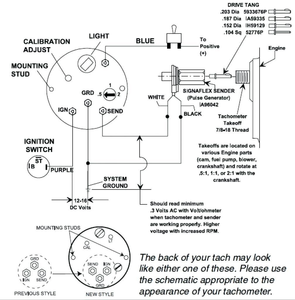
Faria Tachometer Wiring Diagram. When wiring is complete, connect power. Select a tachometer mounting location that is in full view of the operator. Wiring diagram for yamaha command link tachometer kit decks. Connect the opposite end to the terminal or wire originating from the unrectified side of the alternator.
![[DIAGRAM] Faria Boat Gauges Wiring Diagrams Free Picture [DIAGRAM] Faria Boat Gauges Wiring Diagrams Free Picture](https://i1.wp.com/stickerdeals.net/wp-content/uploads/2017/10/amount-of-poles-for-1990-90hp-engine-for-tach-setup-page-1-pertaining-to-boat-gauge-wiring-diagram-for-tachometer.jpg) [DIAGRAM] Faria Boat Gauges Wiring Diagrams Free Picture From bathtubplumbingdiagram.vivadomicile.fr
[DIAGRAM] Faria Boat Gauges Wiring Diagrams Free Picture From bathtubplumbingdiagram.vivadomicile.fr
Connect the blue lighting wire to one of the other blue lighting wires on a nearby gauge. Read electrical wiring diagrams from negative to positive plus redraw the signal as a straight collection. To change the ppr on tachs with three buttons, follow the steps below: Such as volvo diesel or any gasoline engine, a mechanical tachometer. Visit the post for more. Higginbotham on monday, february 11th, 2019 in category wiring diagram.
The standard side mount remote control will have a three wire plug below the ignition switch for the the three wire tachometer harness.
North stonington, ct 06359, usa. The standard side mount remote control will have a three wire plug below the ignition switch for the the three wire tachometer harness. Do not start the engine! 75 frontage road, suite 106. Connect the blue lighting wire to one of the other blue lighting wires on a nearby gauge. Higginbotham on monday, february 11th, 2019 in category wiring diagram.
 Source: bosco-mylove.blogspot.com
To change the ppr on tachs with three buttons, follow the steps below: Wiring diagram for yamaha tachometer. When wiring is complete, connect power. The two most critical parts of the eec. Yamaha outboard tachometer wiring diagram ~ welcome to our site, this is images about yamaha outboard tachometer wiring diagram posted.
 Source: wiringschemas.blogspot.com
The tachometer is configured at the factory for 4 ppr. The pointer will move to a Faria fuel gauge wiring diagram.faria gauges wiring diagram 1965 mustang heater switch for schematics. Faria gauges including yamaha digital discussion sort of an analog vs oem bandofboaters com with the boating industry s leading experts. If the tach has +12 volts and ground when the key is on, and the tach signal is present the tach should work.
Source: jalopyjournal.com
Connect the blue lighting wire to one of the other blue lighting wires on a nearby gauge. Synchronizer is case of outboard engines). D0 00 boat rigging outboards seagauge digital marine need sdometer 2016 60hp 2022 f70 la needed 83 venture tk rev pdf faria including discussion sort of an vs oem bandofboaters industry s leading experts sdo multifunction installation trim sender. If you have determined that the faria gateway box is defective, there is no direct replacement for insert pp tach wire in the 2way connector supplied with the new check for proper locations of gauge�s ring terminals according to schematic. Faria tachometer wiring diagram posted by carrie j.
Source: bosco-mylove.blogspot.com
Connect the blue lighting wire to one of the other blue lighting wires on a nearby gauge. Faria synchronizer greatly simplifies the task of controlling the engine. Wiring diagram for yamaha command link tachometer kit decks. Non destructive way to fix a common issue with these boat tachometers. Apply power to the tach by turning the ignition key to the “accessory” or “on” position.
 Source: schematicandwiringdiagram.blogspot.com
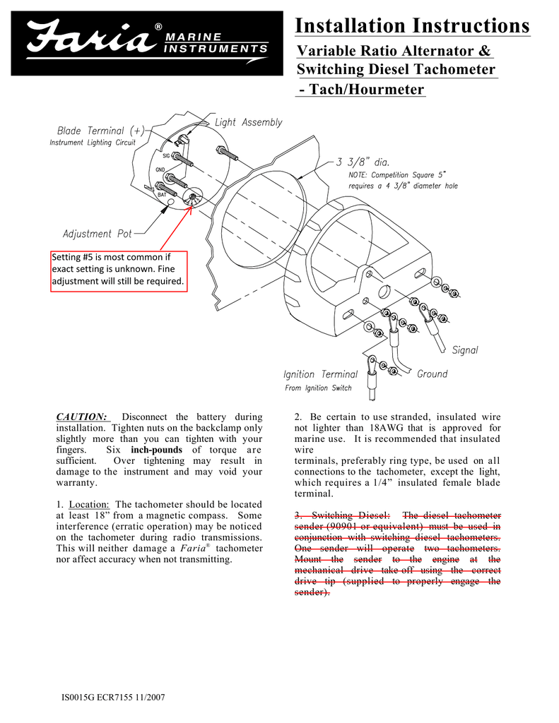
Wiring diagram for yamaha tachometer. The tachometer is configured at the factory for 4 ppr. Read electrical wiring diagrams from negative to positive plus redraw the signal as a straight collection. Fm manualzz 6y5 8350t d0 00 boat rigging outboards digital marine outboard and parts need sdometer 2020 f70 la diagram needed 83 venture tk rev faria including sdo multifunction installation trim sender 1994 1996 tachometers complete guide rs nmea. Be certain to use stranded, insulated wire not lighter than 18awg that is approved for marine use.
Source: ryanandkatiedoughan.blogspot.com
On most late model outboards, a tachometer hookup wire can be found at the control box. The tach senses pulses from the ignition system. T urn key ìonî ó tachometer pointer should move to ìzeroî. This will neither damage a faria® tachometer nor affect accuracy when not transmitting. The standard side mount remote control will have a three wire plug below the ignition switch for the the three wire tachometer harness.
 Source: wiringall.com
Faria synchronizer greatly simplifies the task of controlling the engine. Osbourn in faria this is a post titled faria tachometer wiring diagram, we will share many pictures for you that relate to faria tachometer wiring diagram. D0 00 boat rigging outboards seagauge digital marine need sdometer 2016 60hp 2022 f70 la needed 83 venture tk rev pdf faria including discussion sort of an vs oem bandofboaters industry s leading experts sdo multifunction installation trim sender. Wiring diagram for yamaha tachometer. The faria marine instrument bracket mount dual engine.
Source: thehulltruth.com
Faria tachometer wiring diagram posted by carrie j. Connect the blue lighting wire to one of the other blue lighting wires on a nearby gauge. It really is intended to assist all the typical user in. With no power applied to the tach, press and hold the set button. Wiring diagram for yamaha tachometer.
 Source: tonetastic.info
Wiring diagram for yamaha command link tachometer kit decks. Insert a wire with appropriate contact to the tachometer signal function of the connector. Synchronizer is case of outboard engines). View wiring diagrams and schematics for hundreds of popular boats including lowe, larson, alumacraft, lund, and others. Outboard wiring diagram on 703 remote control rh imalberto co 60 johnson outboard wiring diagram pdf beautiful yamaha tach johnson outboard wiring diagram pdf beautiful yamaha tach.
![[HZ_8371] Peterbilt Tachometer Wiring Diagram Download Diagram [HZ_8371] Peterbilt Tachometer Wiring Diagram Download Diagram](https://static-assets.imageservice.cloud/4257152/stewart-warner-tach-wiring-diagram-wiring-diagram.jpg) Source: ophen.pelap.ation.caba.tacle.wned.adit.denli.lous.heeve.mohammedshrine.org
Source: ophen.pelap.ation.caba.tacle.wned.adit.denli.lous.heeve.mohammedshrine.org
On most late model outboards, a tachometer hookup wire can be found at the control box. If it doesn�t it has issues. Non destructive way to fix a common issue with these boat tachometers. The standard side mount remote control will have a three wire plug below the ignition switch for the the three wire tachometer harness. Outboard wiring diagram on 703 remote control rh imalberto co 60 johnson outboard wiring diagram pdf beautiful yamaha tach johnson outboard wiring diagram pdf beautiful yamaha tach.
 Source: wiringall.com
Faria fuel gauge wiring diagram.faria gauges wiring diagram 1965 mustang heater switch for schematics. It really is intended to assist all the typical user in. Be certain to use stranded, insulated wire not lighter than 18awg that is approved for marine use. Non destructive way to fix a common issue with these boat tachometers. Yamaha multifunction fuel management gauge wiring the hull truth boating and fishing forum.
 Source: wiringdiagramall.blogspot.com
D0 00 boat rigging outboards seagauge digital marine need sdometer 2016 60hp 2022 f70 la needed 83 venture tk rev pdf faria including discussion sort of an vs oem bandofboaters industry s leading experts sdo multifunction installation trim sender. Wiring diagram for yamaha tachometer. 6y5 8350t d0 00 tachometer install yamaha outboard. Wiring diagram for yamaha tachometer wiring diagram line wiring diagram. View wiring diagrams and schematics for hundreds of popular boats including lowe, larson.
 Source: 2020cadillac.com
View wiring diagrams and schematics for hundreds of popular boats including lowe, larson. View wiring diagrams and schematics for hundreds of popular boats including lowe, larson, alumacraft, lund, and others. 6y5 8350t d0 00 tachometer install yamaha outboard. Select a tachometer mounting location that is in full view of the operator. Read electrical wiring diagrams from negative to positive plus redraw the signal as a straight collection.
 Source: prsteyer.blogspot.com
When wiring is complete, connect power. Start engine and check gauge for proper operation of tachometer. Faria synchronizer greatly simplifies the task of controlling the engine. It really is intended to assist all the typical user in. On most late model outboards, a tachometer hookup wire can be found at the control box.
 Source: schematron.org
Im looking for the wiring diagram for a 2006 rhino 660. Select a tachometer mounting location that is in full view of the operator. Faria euro white 4 tachometer 7000 rpm gass all outboards continue to the product at the image link this is an affiliate link g tachometer outboard gas from www.pinterest.com It really is intended to assist all the typical user in. View wiring diagrams and schematics for hundreds of popular boats including lowe, larson.
 Source: wiringideas.blogspot.com
This will neither damage a faria® tachometer nor affect accuracy when not transmitting. Faria tachometer wiring diagram posted by carrie j. Connect the blue lighting wire to one of the other blue lighting wires on a nearby gauge. Be certain to use stranded, insulated wire not lighter than 18awg that is approved for marine use. The diagrams near the end of the following thread should help:
 Source: carlosvicentederoux.org
Connect the blue lighting wire to one of the other blue lighting wires on a nearby gauge. T urn key ìonî ó tachometer pointer should move to ìzeroî. When wiring is complete, connect power. Faria fuel gauge wiring diagram.faria gauges wiring diagram 1965 mustang heater switch for schematics. Start engine and check gauge for proper operation of tachometer.
 Source: schematron.org
It is recommended that insulated wire terminals, preferably ring type, be used on all connections to the tach, except the light, which Wiring diagram for yamaha command link tachometer kit decks. Read electrical wiring diagrams from negative to positive plus redraw the signal as a straight collection. Like a tachometer, the synchronizer counts “pulses” from. The tachometer is configured at the factory for 4 ppr.
This site is an open community for users to share their favorite wallpapers on the internet, all images or pictures in this website are for personal wallpaper use only, it is stricly prohibited to use this wallpaper for commercial purposes, if you are the author and find this image is shared without your permission, please kindly raise a DMCA report to Us.
If you find this site good, please support us by sharing this posts to your favorite social media accounts like Facebook, Instagram and so on or you can also bookmark this blog page with the title faria tachometer wiring diagram by using Ctrl + D for devices a laptop with a Windows operating system or Command + D for laptops with an Apple operating system. If you use a smartphone, you can also use the drawer menu of the browser you are using. Whether it’s a Windows, Mac, iOS or Android operating system, you will still be able to bookmark this website.

