Your Fan control center wiring diagram images are available in this site. Fan control center wiring diagram are a topic that is being searched for and liked by netizens today. You can Download the Fan control center wiring diagram files here. Get all free photos and vectors.
If you’re looking for fan control center wiring diagram pictures information connected with to the fan control center wiring diagram keyword, you have visit the ideal blog. Our website frequently provides you with hints for refferencing the highest quality video and image content, please kindly search and find more enlightening video content and graphics that match your interests.
Fan Control Center Wiring Diagram. Put up by simply admin on january, 3 2016. Collection of fan control center wiring diagram. I bought a new white rodgers fan control center but am not sure which wires go where. Suggested electric fan wiring diagrams page 1 these diagrams show the use of relays, on/off sensors, on/off switches and on/off fan controllers.
 Fan Control Center Wiring Diagram Free Wiring Diagram From ricardolevinsmorales.com
The software comes with all the essential tools. To see most graphics throughout honeywell fan limit switch wiring diagram images gallery make sure you follow this specific. Wire transformer black to the hot black wire in your drawn diagram. Coil blac k y re d n. Re d blac k re d n. It reveals the components of the circuit as simplified forms, as well as the power and signal connections in between the devices.
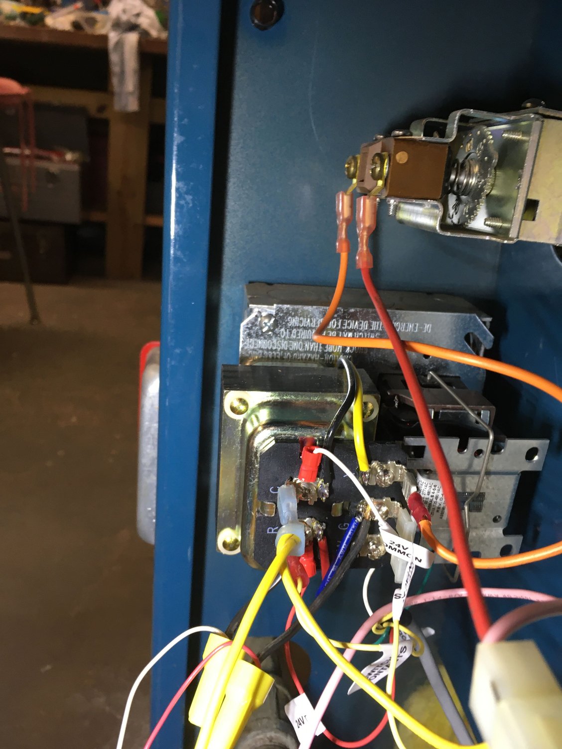
I need help wiring the fan control center and the fan limit switch to power.
Coil blac k y re d n. I really hope you may enjoy it. Nothing here should be confused with the latest generation of pwm variable speed controllers, which have much higher technology, such as a soft start feature and smooth ramping, but not necessarily. Also record all external wiring connections (line and low voltage). The r8285b has dpdt switching for total comfort applications with electronic air. Wire tranformer white to furnace neutral.
 Source: ebay.com
Nothing here should be confused with the latest generation of pwm variable speed controllers, which have much higher technology, such as a soft start feature and smooth ramping, but not necessarily. (of the fan center) parallel to your fan limit. Wire transformer black to the hot black wire in your drawn diagram. Lead wires connecting the low voltage relay coil to terminals I bought a new white rodgers fan control center but am not sure which wires go where.
 Source: ricardolevinsmorales.com
It shows how the electrical wires are interconnected and can also show where fixtures and components might be coupled to the system. I have no wiring diagram for this unit but the m# is g c i need help wiring the fan control center and the fan limit switch to power. If none are provided, the following represents a typical installation. Collection of fan control center wiring diagram. Honeywell fan center wiring diagram schematic.
 Source: irishconnectionsmag.com
The r8285b has dpdt switching for total comfort applications with electronic air. So your diagram black goes to relay com wire and blue goes to the relay n.o. Fan center controls provide convenient low voltage control of one and two speed fan motors and auxiliary circuits in heating, cooling or heating/cooling applications. Replacement relay for fan control center br ow n n.c. Fan control center wiring [ 5 answers ] i�m trying to make this old magic chef furnace work in my garage.
![DOWNLOAD [DIAGRAM] Rotator.php Honeywell Fan Center DOWNLOAD [DIAGRAM] Rotator.php Honeywell Fan Center](https://faceitsalon.com/wp-content/uploads/2018/07/honeywell-fan-limit-switch-wiring-diagram-fan-center-relay-wiring-diagram-at-desk-teamninjaz-me-gas-furnace-fan-relay-wiring-diagram-fan-16c.jpg) Source: craftwiring.madameki.fr
Source: craftwiring.madameki.fr
Wiring diagrams are provided with all fans. 6 25m gas control product information 30 40 50 60 70 80 90. 1 r8285b r8222d 12 60 dpdt 120, 208/240, or 120/208/240 fig. The fan control has 2 black wires coming out of the switch in the back that is normally open. Honeywell fan center wiring diagram schematic.
Source: thehulltruth.com
Transformers fan relay control center hvac 101 you. Wiring diagrams are shown on pages n. Put up by simply admin on january, 3 2016. A wiring diagram is a streamlined standard photographic depiction of an electric circuit. Collection of fan control center wiring diagram.
 Source: diychatroom.com
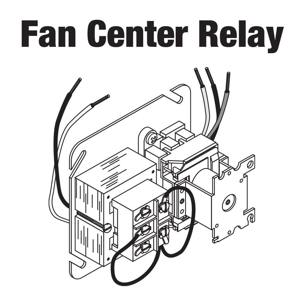
Fan center controls provide convenient low each zc fan 4” square electrical junction box cover. Wire relay com and relay n.o. The r8285b has dpdt switching for total comfort applications with electronic air. It shows how the electrical wires are interconnected and can also show where fixtures and components might be coupled to the system. R8285a1048 honeywell fan center relay transformer spdt 120v.
 Source: alquilercastilloshinchables.info
The fan limit switch has 3 wires going to it (red,blue and black). This impression (honeywell fan center wiring diagram inside honeywell fan limit switch wiring diagram) preceding is actually branded together with: The fan control has 2 black wires coming out of. Wire tranformer white to furnace neutral. It shows how the electrical wires are interconnected and can also show where fixtures and components may be connected to the system.
 Source: diychatroom.com
It shows how the electrical wires are interconnected and can also show where fixtures and components might be coupled to the system. It reveals the components of the circuit as simplified forms, as well as the power and signal connections in between the devices. I got it and the fan control center was broken, laying inside unwired. On the low voltage side. [irp] hvac damper wiring diagram.
 Source: doityourself.com
Also, a black and a white wire that go to the transformer. Make sure all connecting points are the same for both relays. Wiring diagrams are provided with all fans. So your diagram black goes to relay com wire and blue goes to the relay n.o. It reveals the components of the circuit as simplified forms, as well as the power and signal connections in between the devices.
 Source: diychatroom.com
F transistor zc f ab e f zcsp zc zc90 wiring diagram klixon thermostat freezer schematic gb relay/transformer fan center assembly zettler controls. The fan control has 2 black wires coming out of. Wiring diagrams are provided with all fans. I have no wiring diagram for this unit but the m# is g c i need help wiring the fan control center and the fan limit switch to power. Limit switch fan switch fan motor optional remote manual switch for summer fan jumper factory installed on some models to oil burner control or transformer primary diagram using limit in line voltage circuit
 Source: wiring01.blogspot.com
Fan control center wiring diagram. Re d blac k re d n. R8285a1048 honeywell fan center relay transformer spdt 120v. Fan center controls provide convenient low each zc fan 4” square electrical junction box cover. The fan control has 2 black wires coming out of.
 Source: diagramweb.net
It shows how the electrical wires are interconnected and can also show where fixtures and components may be connected to the system. I bought a new white rodgers fan control center but am not sure which wires go where. (of the fan center) parallel to your fan limit. Wire tranformer white to furnace neutral. Transformers fan relay control center hvac 101 you.
 Source: thestylishnomad.com
The fan limit switch has 3 wires going to it (red,blue and black). The fan control has 2 black wires coming out of the switch in the back that is normally open. Wire relay com and relay n.o. Wire transformer black to the hot black wire in your drawn diagram. Fan control center relay amp transformer 90 112 thru 130 manualzz honeywell l4064b combination fan and limit control how to set the temperatures limits on furnace switch i m trying to replace my fan control center white rodgers s84 17 with its replacement rogers 90 112 the wires
 Source: panoramaline.com
It reveals the components of the circuit as simplified forms, as well as the power and signal connections in between the devices. The r8285b has dpdt switching for total comfort applications with electronic air. R8285a1048 honeywell fan center relay transformer spdt 120v. To see most graphics throughout honeywell fan limit switch wiring diagram images gallery make sure you follow this specific. Many of the newer furnaces do.
Source: hearth.com
Fan control center wiring diagram. Wiring diagrams are shown on pages n. Connect in accordance with the wiring diagrams provided by the equipment manufacturer. Wiring wiring must be in accordance with as/nzs3000:2007 and local supply regulations. It shows how the electrical wires are interconnected and can also show where fixtures and components might be coupled to the system.
 Source: schematicandwiringdiagram.blogspot.com
F transistor zc f ab e f zcsp zc zc90 wiring diagram klixon thermostat freezer schematic gb relay/transformer fan center assembly zettler controls. R8285a1048 honeywell fan center relay transformer spdt 120v. It reveals the components of the circuit as simplified forms, as well as the power and signal connections in between the devices. Coil blac k y re d n. And 2 red wires from a switch that is normally closed.
 Source: diychatroom.com
Viole t co mm on c g w coil r blac k g blac k r re d/ ye l n. Transformers fan relay control center hvac 101 you. The fan control has 2 black wires coming out of the switch in the back that is normally open. Collection of fan control center wiring diagram. Symbols that stand for the parts in the circuit and lines that.
 Source: diychatroom.com
Replacement relay for fan control center br ow n n.c. Magic chef hvac wiring diagram daily update. Honeywell fan center wiring diagram schematic. The fan limit switch has 3 wires going to it (red,blue and black). I need help wiring the fan control center and the fan limit switch to power.
This site is an open community for users to submit their favorite wallpapers on the internet, all images or pictures in this website are for personal wallpaper use only, it is stricly prohibited to use this wallpaper for commercial purposes, if you are the author and find this image is shared without your permission, please kindly raise a DMCA report to Us.
If you find this site good, please support us by sharing this posts to your own social media accounts like Facebook, Instagram and so on or you can also save this blog page with the title fan control center wiring diagram by using Ctrl + D for devices a laptop with a Windows operating system or Command + D for laptops with an Apple operating system. If you use a smartphone, you can also use the drawer menu of the browser you are using. Whether it’s a Windows, Mac, iOS or Android operating system, you will still be able to bookmark this website.


