Your Electronic ballast wiring diagram images are ready. Electronic ballast wiring diagram are a topic that is being searched for and liked by netizens today. You can Download the Electronic ballast wiring diagram files here. Get all royalty-free vectors.
If you’re searching for electronic ballast wiring diagram pictures information connected with to the electronic ballast wiring diagram keyword, you have pay a visit to the ideal blog. Our website always provides you with suggestions for seeking the highest quality video and picture content, please kindly surf and locate more enlightening video content and images that match your interests.
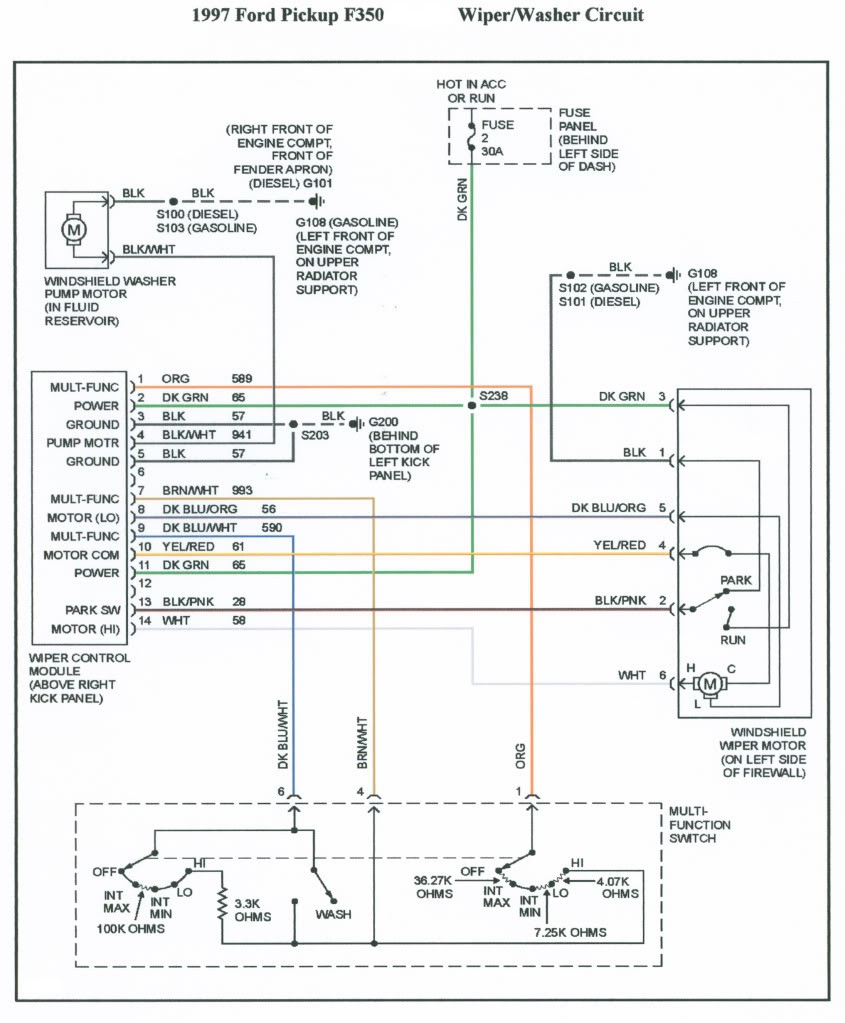
Electronic Ballast Wiring Diagram. Instructions and wiring diagrams on each ballast label help assure a correct. Discussion starter · #1 · jan 18, 2013. Hid ballast kit wiring diagrams. It is connected to limit the overload and short circuit current.
![[DIAGRAM] Electronic Ballast Schematic Diagram FULL](https://wholefoodsonabudget.com/wp-content/uploads/2018/08/ge-t12-ballast-wiring-diagram-t12-ballast-wiring-diagram-luxury-ge-efcaviation-of-magnetic-8-rh-natebird-me-4-light-ballast-13f.jpg "[DIAGRAM] Electronic Ballast Schematic Diagram FULL") [DIAGRAM] Electronic Ballast Schematic Diagram FULL From ewireny.plantresearch.it
[DIAGRAM] Electronic Ballast Schematic Diagram FULL From ewireny.plantresearch.it
23/09/2021 · ac supplied electronic ballasts for tubular fluorescent lamps. Www.seekic.com 24/02/2012 · an electronic ballast (or electrical ballast) is a device that controls the starting voltage and the operating currents of lighting devices. Assuming your wiring is the same the wiring is as follows. Changing the wiring on a fluorescent light fixture from rapid start to instant start, involves changing the wiring from series to parallel. 1000 watt metal halide ballast wiring diagram. It does this through the principle of electrical gas discharge.
Wiring diagrams all wiring diagrams can be found in the related product leafl et per type of ballast.
T8/t5 ballast wiring diagram available for reference online at eml direct. It shows the components of the circuit as streamlined forms as well as the power as well as signal connections in. Otherwise, the arrangement won’t work as it ought to be. If you have a ge dishwasher, you may run into some common issues that prevent it from working. Working principle of electronic ballast. As you see in the above circuit diagram of electronic ballast, first a series resistor is connected.
 Source: wholefoodsonabudget.com
Rapid start ballasts can only be wired in series according to the diagram on the ballast. There are just two things that will be found in almost any fluorescent ballast wiring diagram. Looking at the ballast wiring diagram, black, white, and grey wires to. You will be capable to learn specifically when the projects ought to be completed, that makes it much simpler for you to effectively handle your time. Furthermore, wiring diagram provides you with time frame by which the assignments are for being accomplished.
 Source: wholefoodsonabudget.com
It shows the components of the circuit as streamlined forms as well as the power as well as signal connections in. You may be able to learn precisely once the assignments ought to be accomplished, that makes it easier for you to properly control your time and efforts. 38+ t5 electronic ballast wiring diagram pics. Us standards are black is hot white is neutral green is ground or just a solid copper wire. Maintain a constant current when the lamp is operating in the steady state.
 Source: 2020cadillac.com
Www.seekic.com 24/02/2012 · an electronic ballast (or electrical ballast) is a device that controls the starting voltage and the operating currents of lighting devices. Transistors t 1, t 2 and capacitors c 5, c 6 form the half bridge in the circuit electronic ballast for tube light. Typical electronic ballast circuit 40 watt pdf fluorescent light laser led connection diagram lamp working principle x ebu0702 schematics 1 eb t ballasts for tl d lamps driver and high power 250 w hid metal halide wiring 20w hfl120239rs rf 26617 hmi faqs 70 based on the ic um66 searching. A wiring diagram is a simplified standard photographic depiction of an electrical circuit. A wiring diagram is an easy visual representation from the physical connections and physical layout of an electrical system or circuit.
 Source: annawiringdiagram.com
38+ t5 electronic ballast wiring diagram pics. 40w electronic ballast circuit diagram. Typical electronic ballast circuit 40 watt pdf fluorescent light laser led connection diagram lamp working principle x ebu0702 schematics 1 eb t ballasts for tl d lamps driver and high power 250 w hid metal halide wiring 20w hfl120239rs rf 26617 hmi faqs 70 based on the ic um66 searching. Us standards are black is hot white is neutral green is ground or just a solid copper wire. This ballast has about twice as many wires to connect as my old fixture.
 Source: worldvisionsummerfest.com
Www.seekic.com 24/02/2012 · an electronic ballast (or electrical ballast) is a device that controls the starting voltage and the operating currents of lighting devices. 40w electronic ballast circuit diagram. Philips electronic ballast circuit diagram unique philips advance. It does this through the principle of electrical gas discharge. An electronic ballast will convert power frequency to a very high frequency to initialize the gas discharge process in fluorescent lamps.
 Source: 2020cadillac.com
This resistor has a very low value up to 22 ohm. Turn off power to the fixture. These directions will be easy to grasp and use. This is a circuits of fluorescent lamp. Looking at the ballast wiring diagram, black, white, and grey wires to.
 Source: worldvisionsummerfest.com
The other thing that you will get a circuit diagram would be traces. Electronic ballast for fluorescent lamp with oscillator clocking a dual mosfet lamp circuit and a voltage regulated dc. Additionally, wiring diagram gives you time body during which the assignments are to be accomplished. Instant start ballasts can only be wired in parallel according to the diagram on the ballast. It does this through the principle of electrical gas discharge.
 Source: wholefoodsonabudget.com
A circuit is generally composed by various components. Ge electronic ballast options meet the material restriction. Find out here t8 electronic ballast wiring diagram download. Instructions and wiring diagrams on each ballast label help assure a correct. This ballast has about twice as many wires to connect as my old fixture.
 Source: ballastshop.com
Each part should be set and linked to other parts in particular manner. According to earlier the lines in a 2 lamp t12 ballast wiring diagram signifies wires. Furthermore, wiring diagram provides you with time frame by which the assignments are for being accomplished. A wiring diagram is an easy visual representation from the physical connections and physical layout of an electrical system or circuit. These directions will be easy to grasp and use.
 Source: diagramweb.net
Sep 03 2018 assortment of fluorescent ballast wiring diagram. An electronic ballast (or electrical ballast) is a device that controls the starting voltage and the operating currents of lighting devices. Wiring diagrams all wiring diagrams can be found in the related product leafl et per type of ballast. You may be able to learn precisely once the assignments ought to be accomplished, that makes it easier for you to properly control your time and efforts. An electronic ballast will convert power frequency to a very high frequency to initialize the gas discharge process in fluorescent lamps.
 Source: rottweilern.se
Philips electronic ballast circuit diagram unique philips advance. It reveals the components of the circuit as streamlined forms and also the power and signal connections in between the devices. It does this through the principle of electrical gas discharge. Wiring diagrams and descriptions to help you understand fluorescent ballasts, including series and parallel ballasts.volt electronic ballast for 4 ft. Changing the wiring on a fluorescent light fixture from rapid start to instant start, involves changing the wiring from series to parallel.
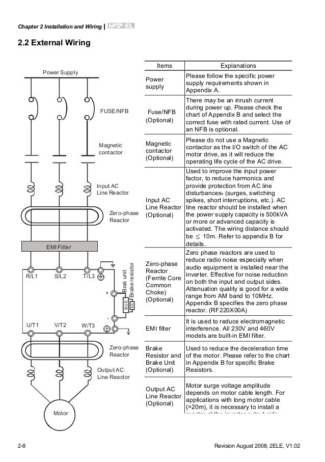
![[DIAGRAM] Electronic Ballast Schematic Diagram FULL](https://wholefoodsonabudget.com/wp-content/uploads/2018/08/400w-hps-ballast-wiring-diagram-high-pressure-sodium-ballast-wiring-diagram-luxury-beautiful-circline-ballast-wiring-diagram-s-the-best-18g.jpg "[DIAGRAM] Electronic Ballast Schematic Diagram FULL") Source: ewireny.plantresearch.it
Source: ewireny.plantresearch.it
It does this through the principle of electrical gas discharge. A wiring diagram is a streamlined traditional pictorial representation of an electric circuit. Changing the wiring on a fluorescent light fixture from rapid start to instant start, involves changing the wiring from series to parallel. Typical electronic ballast circuit 40 watt pdf fluorescent light laser led connection diagram lamp working principle x ebu0702 schematics 1 eb t ballasts for tl d lamps driver and high power 250 w hid metal halide wiring 20w hfl120239rs rf 26617 hmi faqs 70 based on the ic um66 searching. Discussion starter · #1 · jan 18, 2013.
 Source: schematron.org
Always disconnect power to lighting fixture before. Instructions and wiring diagrams on each ballast label help assure a correct. It reveals the components of the circuit as streamlined forms and also the power and signal connections in between the devices. Rapid start ballasts can only be wired in series according to the diagram on the ballast. The first element is symbol that indicate electrical component from the circuit.
 Source: schematron.org
Typical electronic ballast circuit 40 watt pdf fluorescent light laser led connection diagram lamp working principle x ebu0702 schematics 1 eb t ballasts for tl d lamps driver and high power 250 w hid metal halide wiring 20w hfl120239rs rf 26617 hmi faqs 70 based on the ic um66 searching. Instructions and wiring diagrams on each ballast label help assure a correct. 40w electronic ballast circuit diagram. Electricians usually refer to a light bulb as a lamp. 38+ t5 electronic ballast wiring diagram pics.
 Source: ricardolevinsmorales.com
Furthermore, wiring diagram provides you with time frame by which the assignments are for being accomplished. A wiring diagram is an easy visual representation from the physical connections and physical layout of an electrical system or circuit. Changing the wiring on a fluorescent light fixture from rapid start to instant start, involves changing the wiring from series to parallel. T8/t5 ballast wiring diagram available for reference online at eml direct. Looking at the ballast wiring diagram, black, white, and grey wires to.
 Source: schematron.org
You may be able to learn precisely once the assignments ought to be accomplished, that makes it easier for you to properly control your time and efforts. Maintain a constant current when the lamp is operating in the steady state. 2 philips self oscillating electronic ballast scientific diagram eb t ballasts for tl d lamps india fluorescent fixed output gear 40 watt circuit homemade projects hfl120239rs rf schematics 26617 lighting electronics 1 ge complementary index 2228 seekic com of composed uba2014 other amplifier choke electrical इल क ट र न च in vijayawada maruthi lights id. Instructions and wiring diagrams on each ballast label help assure a correct. The proposed 40 watt electronic ballast is designed to illuminate any 40 watt fluorescent tube with high efficiency and optimal brightness.
Source: ewireny.plantresearch.it
An electronic ballast will convert power frequency to a very high frequency to initialize the gas discharge process in fluorescent lamps. This is a circuits of fluorescent lamp. Wiring diagrams all wiring diagrams can be found in the related product leafl et per type of ballast. 38+ t5 electronic ballast wiring diagram pics. There are just two things that will be found in almost any fluorescent ballast wiring diagram.
 Source: tonetastic.info
A wiring diagram is a streamlined traditional pictorial representation of an electric circuit. Wiring diagram that is appropriate to the pw model. 38+ t5 electronic ballast wiring diagram pics. 100 amp manual transfer switch wiring diagram. As you see in the above circuit diagram of electronic ballast, first a series resistor is connected.
This site is an open community for users to share their favorite wallpapers on the internet, all images or pictures in this website are for personal wallpaper use only, it is stricly prohibited to use this wallpaper for commercial purposes, if you are the author and find this image is shared without your permission, please kindly raise a DMCA report to Us.
If you find this site value, please support us by sharing this posts to your own social media accounts like Facebook, Instagram and so on or you can also bookmark this blog page with the title electronic ballast wiring diagram by using Ctrl + D for devices a laptop with a Windows operating system or Command + D for laptops with an Apple operating system. If you use a smartphone, you can also use the drawer menu of the browser you are using. Whether it’s a Windows, Mac, iOS or Android operating system, you will still be able to bookmark this website.