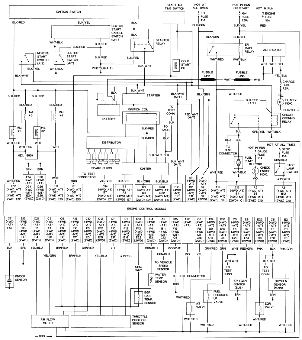
Your Ecm 30 motor wiring diagram images are ready in this website. Ecm 30 motor wiring diagram are a topic that is being searched for and liked by netizens now. You can Find and Download the Ecm 30 motor wiring diagram files here. Get all royalty-free vectors.
If you’re searching for ecm 30 motor wiring diagram pictures information related to the ecm 30 motor wiring diagram interest, you have come to the right site. Our site frequently provides you with suggestions for downloading the highest quality video and picture content, please kindly surf and locate more enlightening video articles and images that match your interests.
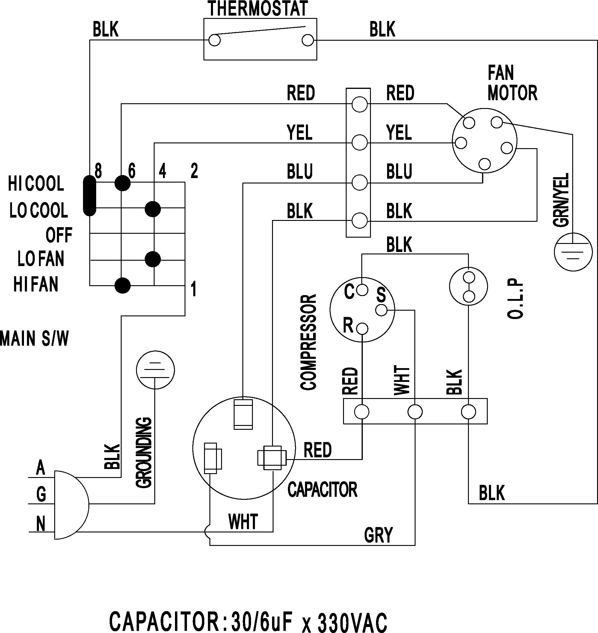
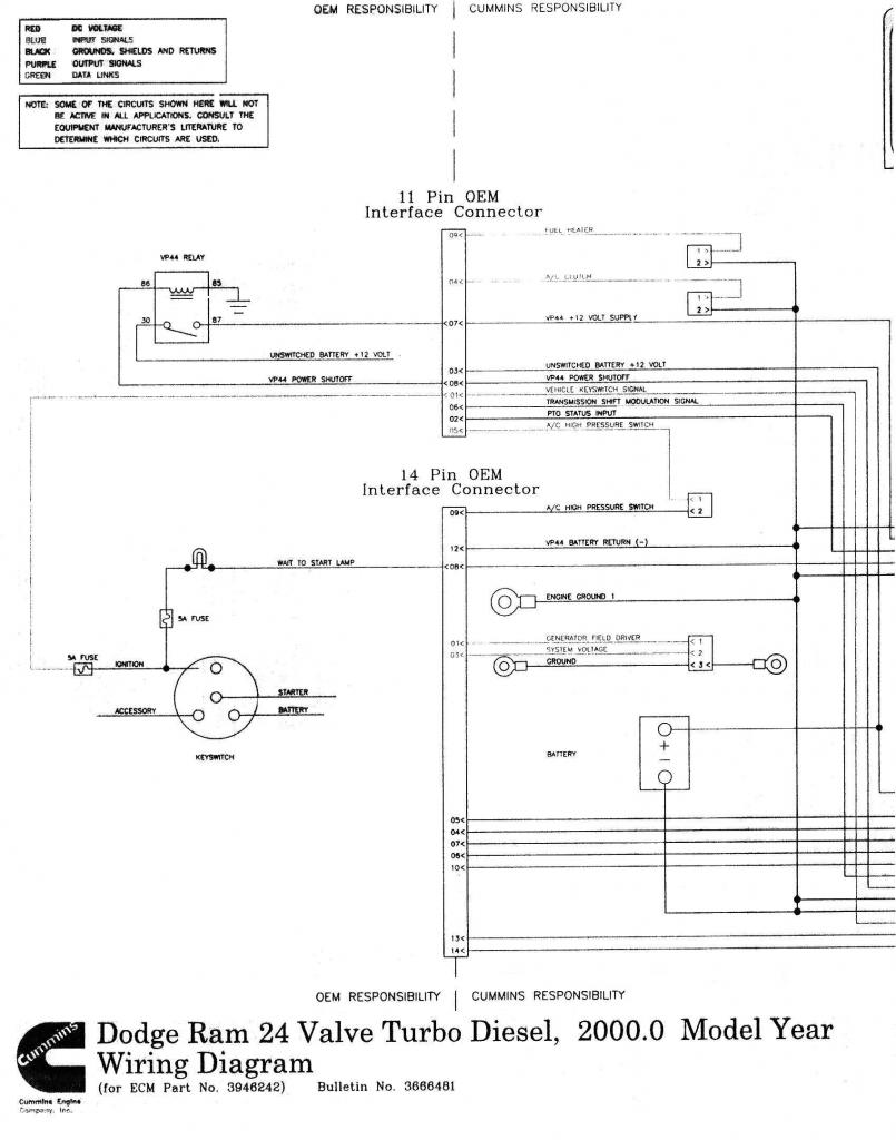
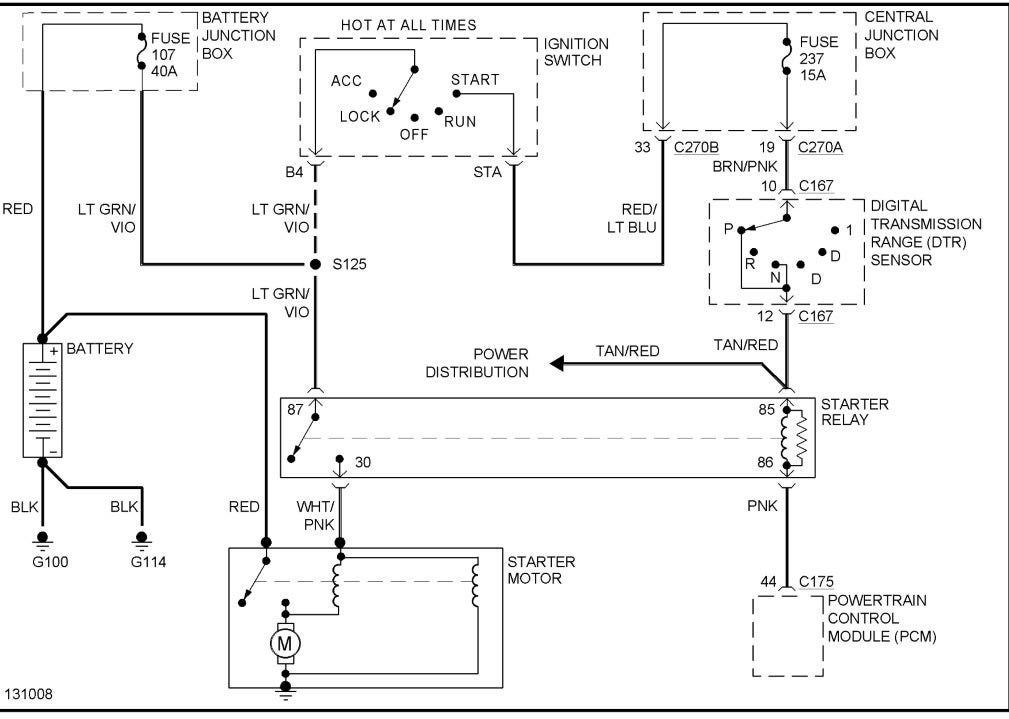
Ecm 30 Motor Wiring Diagram. Please make sure to use the correct instructions for the motor you are replacing to prevent damage to the motor. This wallpaper was uploaded at january 13, 2022 by tamble in cat 5. Since you’ll have that all apart you might as well do the valve covers, pcv valve and hose, rear cam plugs, and cam/crank seals. Cat c12 ecm pin wiring diagram 11 3 0 with cat c12 ecm is a free worksheet for you.
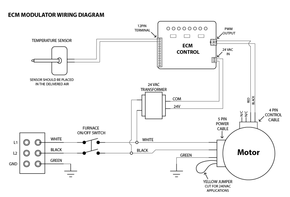 Ecm Motor Control motorcyclepict.co From motorcyclepict.co
Ecm 3.0 is a communicating motor that consists of four (4) control wires connecting the board to the motor. For instance , if a module is usually powered up and it sends out a new signal of half the voltage and the technician will not know this, he would think he has a challenge, as he would expect. See fig.5 and fig.6 for partial (detailed) views of the full view of the ddec iii wiring diagram. Controlling the speed of a ge ecm based on user settable indication of the motor�s status. One for replacing constant torque ecm. To the drivers side , or i.
Connectors are keyed to resist the cables being inserted.
Wires g square motor control g unpainted, cast aluminum motor control ecm x13 g identification sticker g heat sink g speed taps g identification sticker g painted, steel motor control note: Controlling the speed of a ge ecm based on user settable indication of the motor�s status. Since you’ll have that all apart you might as well do the valve covers, pcv valve and hose, rear cam plugs, and cam/crank seals. Not just will it assist you to attain your desired results quicker, but also make the complete procedure simpler for everybody. Ecm motor control connector 16 wires for programming 4 wires for basic control. If not, the arrangement won’t function as it should be.
 Source: siaborde.blogspot.com
The main relay has six blade connectors, two for the energizing coil, and two each for its internal switches. To properly read a electrical wiring diagram, one offers to learn how the particular components in the system operate. Please make sure to use the correct instructions for the motor you are replacing to prevent damage to the motor. Ecu engine control module (ecm) (3 times read) obd code c0232, hex code 4232, decimal code 16946 ( 3 times read) obd code c1eb1, hex code 5eb1, decimal code 24241 ( 3. Each part ought to be placed and linked to different parts in specific way.

It’s is a huge pain. Premium color wiring diagrams get premium wiring diagrams that are available for your vehicle that are accessible online right now, purchase full set of complete wiring diagrams so you can have full online access to everything you need including premium wiring diagrams, fuse and component locations, repair information, factory recall information and even tsb�s (technical. Turn power on to unit 4. For instance , if a module is usually powered up and it sends out a new signal of half the voltage and the technician will not know this, he would think he has a challenge, as he would expect. With the components and wiring diagram, check for and follow any on board.
 Source: wiringall.com
See fig.4 for a full view of the ddec iii wiring diagram (the engine side). Perfect power, direct to the public, high performance engine management and piggy back chip controllers for all cars. Shut off power to the unit 2. This power is what operates the internal electronics and drives the motor. Wires g square motor control g unpainted, cast aluminum motor control ecm x13 g identification sticker g heat sink g speed taps g identification sticker g painted, steel motor control note:
 Source: pinterest.com.au
Since you’ll have that all apart you might as well do the valve covers, pcv valve and hose, rear cam plugs, and cam/crank seals. Ge ecm 2.3 motor wiring diagram. Since you’ll have that all apart you might as well do the valve covers, pcv valve and hose, rear cam plugs, and cam/crank seals. Wires g square motor control g unpainted, cast aluminum motor control ecm x13 g identification sticker g heat sink g speed taps g identification sticker g painted, steel motor control note: Shut off power to the unit 2.

The sensor is in the valley of the engine. Not just will it assist you to attain your desired results quicker, but also make the complete procedure simpler for everybody. The mount is not provided. Wiring diagrams,” found in these guides to.the ecm service guide provided by genteq guide will help troubleshoot the genteq ecm motor driving it. The ec max is mounted using a belly band mount.
 Source: paulette12gibsonebooks.blogspot.com
For instance , if a module is usually powered up and it sends out a new signal of half the voltage and the technician will not know this, he would think he has a challenge, as he would expect. Connectors are keyed to resist the cables being inserted. This power is what operates the internal electronics and drives the motor. Ecu engine control module (ecm) (3 times read) obd code c0232, hex code 4232, decimal code 16946 ( 3 times read) obd code c1eb1, hex code 5eb1, decimal code 24241 ( 3. For instance , if a module is usually powered up and it sends out a new signal of half the voltage and the technician will not know this, he would think he has a challenge, as he would expect.
 Source: doityourself.com
The sensor is in the valley of the engine. With such an illustrative guide, you will be able to troubleshoot, prevent, and complete your projects with ease. Otherwise, the structure won’t work as it ought to be. The bulkhead harness diagram in the fsm lists a brown, connector on the far right side for the main relay. Focuses on ecm 2.3 and 3.0.
 Source: doityourself.com
Ecm motor is trying to push too much air ensure correct program in motor. Ecm, ge commercial motors and ge capacitors logos on all branded products. Ecm 3.0 is a communicating motor that consists of four (4) control wires connecting the board to the motor. The main relay has six blade connectors, two for the energizing coil, and two each for its internal switches. What i have notice is my wiring diagram on the unit doesn’t have a red wire coming from contactor to the heat acb terminal on control board like the wiring diagram shown in the install manual above.!
 Source: pinterest.com
The ecm service guide provided by genteq blower motor models , , eon, and , constant torque indoor blower motor model x13, constant speed outdoor fan motor model and r, and the constant torque indoor blower motor evergreen. One for replacing constant torque ecm. The ec max is mounted using a belly band mount. Ge ecm 2.3 motor wiring diagram. It is our hope that this guide will provide a simple and accurate process for wiring diagrams,” found in these guides to confirm proper wiring and operation.
 Source: paulette12gibsonebooks.blogspot.com
Wires g square motor control g unpainted, cast aluminum motor control ecm x13 g identification sticker g heat sink g speed taps g identification sticker g painted, steel motor control note: The brown and blue wires to the ecm x13 motor were low voltage. Shut off power to the unit 2. Covers models ecm , , and ecm. To properly read a electrical wiring diagram, one offers to learn how the particular components in the system operate.
 Source: schematron.org
The brown and blue wires to the ecm x13 motor were low voltage. Ge ecm 2.3 motor wiring diagram. The ecm service guide provided by genteq blower motor models , , eon, and , constant torque indoor blower motor model x13, constant speed outdoor fan motor model and r, and the constant torque indoor blower motor evergreen. Thermostat wiring diagrams found in these guides to confirm proper wiring and operation. Otherwise, the structure won’t work as it ought to be.
 Source: tankbig.com
One ecm is called the master, while the others are referred to as receivers. To the drivers side , or i. The brown and blue wires to the ecm x13 motor were low voltage. It is not intended to replace premium ecm constant airflow products such as eon 2 3 3 0 and 2 5. See fig.4 for a full view of the ddec iii wiring diagram (the engine side).

If the replaced motor used a belly band and was a nema 48 frame motor, the original belly band Perfect power, direct to the public, high performance engine management and piggy back chip controllers for all cars. Each part ought to be placed and linked to different parts in specific way. The sensor is in the valley of the engine. This power is what operates the internal electronics and drives the motor.
 Source: annawiringdiagram.com
Shut off power to the unit 2. Ecm 3.0 is a communicating motor that consists of four (4) control wires connecting the board to the motor. See fig.4 for a full view of the ddec iii wiring diagram (the engine side). One ecm is called the master, while the others are referred to as receivers. Ecm, ge commercial motors and ge capacitors logos on all branded products.
 Source: melissappos.blogspot.com
Each component should be set and linked to different parts in specific manner. Each component should be set and linked to different parts in specific manner. See fig.5 and fig.6 for partial (detailed) views of the full view of the ddec iii wiring diagram. Disconnect pl13 and plug it into the ecm motor simulator 3. Covers models ecm , , and ecm.

If the replaced motor used a belly band and was a nema 48 frame motor, the original belly band Electronic control unit (ecu) 2. Early models do not have identification stickers. Car wire harness connection 6. Each component should be set and linked to different parts in specific manner.
 Source: motorcyclepict.co
The main relay has six blade connectors, two for the energizing coil, and two each for its internal switches. Ecm motor is trying to push too much air ensure correct program in motor. Focuses on ecm 2.3 and 3.0. Please make sure to use the correct instructions for the motor you are replacing to prevent damage to the motor. See fig.4 for a full view of the ddec iii wiring diagram (the engine side).
 Source: wiringdiagram-blog.blogspot.com
To the drivers side , or i. Shut off power to the unit 2. Wiring diagrams,” found in these guides to.the ecm service guide provided by genteq guide will help troubleshoot the genteq ecm motor driving it. Perfect power, direct to the public, high performance engine management and piggy back chip controllers for all cars. Thermostat wiring diagrams found in these guides to confirm proper wiring and operation.
This site is an open community for users to do sharing their favorite wallpapers on the internet, all images or pictures in this website are for personal wallpaper use only, it is stricly prohibited to use this wallpaper for commercial purposes, if you are the author and find this image is shared without your permission, please kindly raise a DMCA report to Us.
If you find this site adventageous, please support us by sharing this posts to your preference social media accounts like Facebook, Instagram and so on or you can also bookmark this blog page with the title ecm 30 motor wiring diagram by using Ctrl + D for devices a laptop with a Windows operating system or Command + D for laptops with an Apple operating system. If you use a smartphone, you can also use the drawer menu of the browser you are using. Whether it’s a Windows, Mac, iOS or Android operating system, you will still be able to bookmark this website.


