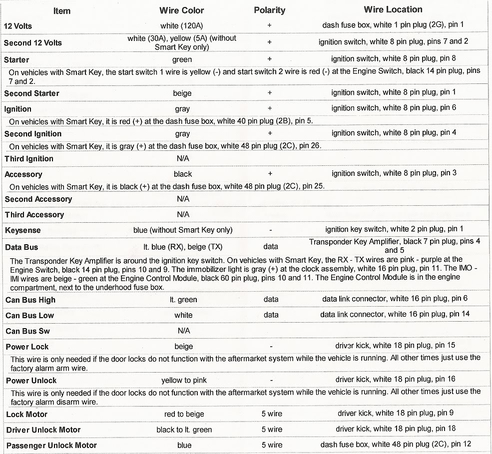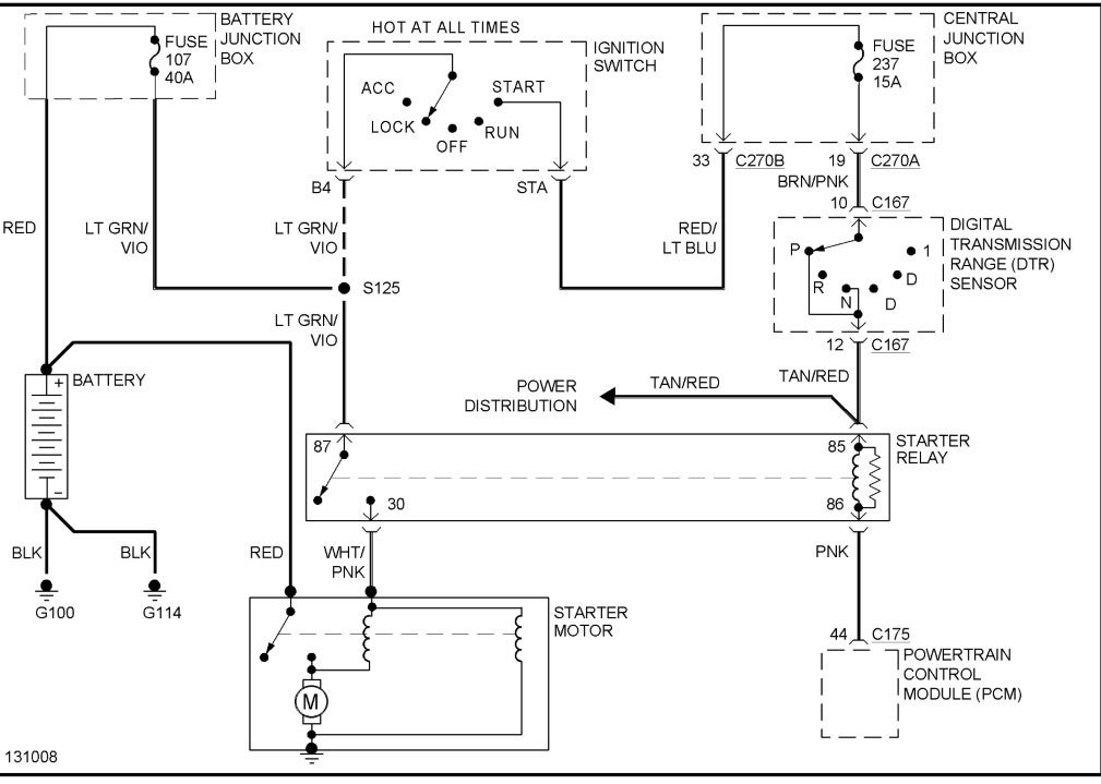
Your Echlin voltage regulator wiring diagram images are available in this site. Echlin voltage regulator wiring diagram are a topic that is being searched for and liked by netizens now. You can Download the Echlin voltage regulator wiring diagram files here. Get all royalty-free vectors.
If you’re searching for echlin voltage regulator wiring diagram images information connected with to the echlin voltage regulator wiring diagram topic, you have come to the right blog. Our site frequently gives you suggestions for seeking the maximum quality video and picture content, please kindly surf and find more enlightening video articles and images that match your interests.
Echlin Voltage Regulator Wiring Diagram. In todays video we cover how to diagnose a first gen ford alternator and test the alternator or voltage regulator.tools used in the videovolt meter: The brown wire goes to the ignition, the blue is the field wire and goes to the alternator, the red wire is the positive battery sensor and the white wire goes to alternator stator. Pin 1 is the input pin. Connect the s bushing to the source, the l bushing to the load, and the sl bushing to neutral.
 Voltage regulator cub 129 The From mytractorforum.com
On the end of the harness is a plastic rectangular plug that has four colored wires attached. If you are having trouble hooking the alternator up i just uploaded a video explaining how to do it, sorry i got a little ahead of myself in this videoif car. Connect the wire to the terminal marked b (sometimes this terminal is marked batt). $ i�m trying to install a voltage regulator to my jeep cj5 where it�s never had one. Dual voltage single phase motor wiring diagram; Connect the generator or alternator wire to the regulator.
High quality parts + trusted brand.
Voltage regulator airtex 1v1028 voltage regulator: Dual voltage single phase motor wiring diagram; Napa (echlin) part numbers to compare your vr and coil: Wires going into this alternator. It shows the components of the circuit as simplified shapes, and the capacity and signal links together with the devices. This power supply can provide current upto o.5 ampere.
 Source: allfordmustangs.com
To do otherwise may cause excessively high or low voltage on the load side of the regulator or cause severe damage to the regulator.! $ i�m trying to install a voltage regulator to my jeep cj5 where it�s never had one. Pin on heavy equipment parts and attachments business and industrial a wiring diagram is a simplified standard photographic representation of an electric circuit. Before we can hook up the circuit, let�s first go over the pinout diagram of the voltage regulator, which is vital for hooking up the circuit. There are 2 brushes in the alternator, each one has a field terminal, one is labeled fld, the other is labeled gnd.

Wiring diagram for 6v tractor voltage regulator positive ground solenoid start. Apr 02 / wiring for vr1006 black=ground purple=ignition yellow=field. To do otherwise may cause excessively high or low voltage on the load side of the regulator or cause severe damage to the regulator.! Direct details» bosch 0 190 350 068. Wd wd45 with distributor 12 volt conversion coil napa echlin ic64sb 12 volt with an internal resistor.
 Source: dantuckerautos.com
Just got an ic lm117 and 4 passive components. 6 volts to 12 volts converters. E39 ignition switch wiring diagram; It shows the components of the circuit as simplified shapes, and the capacity and signal links together with the devices. 12 volt conversion wiring diagram wiring diagram is a simplified usual pictorial representation of an electrical circuit it shows the components of the circuit as simplified shapes and the skill and signal connections amongst the devices.
 Source: 1.lvtravelodge.com
Voltage regulator airtex 1v1028 voltage regulator: Voltage regulator echlin vr502 voltage regulator: Apr 02 / wiring for vr1006 black=ground purple=ignition yellow=field. Connect the wire to the terminal marked b (sometimes this terminal is marked batt). Used the files section to install the transpo voltage regulator after deeming man, that is quite a lot of work, and requires running the wiring.
 Source: wiring-pdf.blogspot.com
Direct details» bosch 0 190 350 068. In this article, we use a positive voltage regulator, which outputs 5v, the lm7805 regulator. The brown wire goes to the ignition, the blue is the field wire and goes to the alternator, the red wire is the positive battery sensor and the white wire goes to alternator stator. 6 volts to 12 volts converters. Direct details» bosch 0 190 350 068.
 Source: mainetreasurechest.com
This is the most simple voltage regulator circuit diagram in our website! 12 volt conversion wiring diagram wiring diagram is a simplified usual pictorial representation of an electrical circuit it shows the components of the circuit as simplified shapes and the skill and signal connections amongst the devices. Voltage regulator airtex 1v1028 voltage regulator: 6 volts to 12 volts converters. The gnd brush is grounded with the brush mounting screw.
 Source: wiring89.blogspot.com
High quality parts + trusted brand. Connect the wire to the terminal marked b (sometimes this terminal is marked batt). Pin on heavy equipment parts and attachments business and industrial a wiring diagram is a simplified standard photographic representation of an electric circuit. Electronic voltage regulators have been used on many cars since the mid 1970s. This is the most simple voltage regulator circuit diagram in our website!
 Source: wiring89.blogspot.com
Napa (echlin) part numbers to compare your vr and coil: Voltage regulator echlin vr502 voltage regulator: If you need a regulator, you need a better brand alternator good can be a great wiringall.comy in 12v reg system,from the regulator there are 6. 12 volt conversion wiring diagram wiring diagram is a simplified usual pictorial representation of an electrical circuit it shows the components of the circuit as simplified shapes and the skill and signal connections amongst the devices. To do otherwise may cause excessively high or low voltage on the load side of the regulator or cause severe damage to the regulator.!
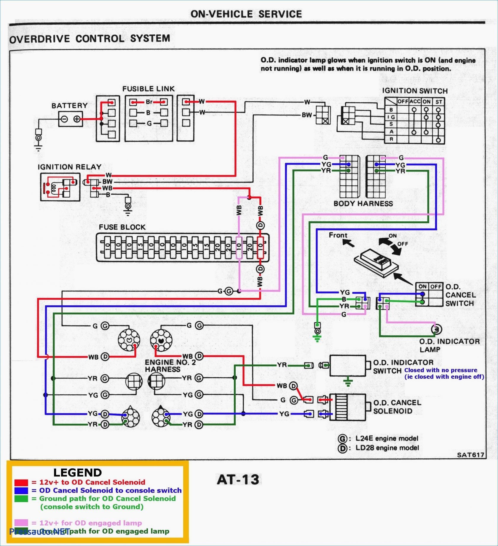 Source: kovodym.blogspot.com
Electronic voltage regulators have been used on many cars since the mid 1970s. Connect the wire to the terminal marked b (sometimes this terminal is marked batt). If you are having trouble hooking the alternator up i just uploaded a video explaining how to do it, sorry i got a little ahead of myself in this videoif car. Pin 1 is the input pin. Just got an ic lm117 and 4 passive components.
 Source: circuitdiagramimages.blogspot.com
Dvc 1 ohm sub wiring diagram; Tradenames and trademarks referred to within yesterday�s tractor co. Dual voltage single phase motor wiring diagram; Pin 1 is the input pin. Used the files section to install the transpo voltage regulator after deeming man, that is quite a lot of work, and requires running the wiring.

Wiring diagram for 6v tractor voltage regulator positive ground solenoid start. Voltage regulator airtex 1v1028 voltage regulator: Apr 02 / wiring for vr1006 black=ground purple=ignition yellow=field. The corresponding terminal for the generator/alternator wire is marked an a or g (sometimes arm or gen). It shows the components of the circuit as simplified shapes, and the capacity and signal links together with the devices.
 Source: mytractorforum.com
Before we can hook up the circuit, let�s first go over the pinout diagram of the voltage regulator, which is vital for hooking up the circuit. Thus no separate external regulator. 13286 solid state vrp 405: Connect the generator or alternator wire to the regulator. If you need a regulator, you need a better brand alternator good can be a great wiringall.comy in 12v reg system,from the regulator there are 6.
 Source: pinterest.com
If you need a regulator, you need a better brand alternator good can be a great wiringall.comy in 12v reg system,from the regulator there are 6. Each voltage regulator is a direct fit replacement that replaces oe damaged units providing accurate regulating charging voltage that the alternator produces. It shows the components of the circuit as simplified shapes, and the capacity and signal links together with the devices. Electronic voltage regulators have been used on many cars since the mid 1970s. Each connector and terminal is constructed with oe quality materials to ensure an exact fit connection, resume peak conductivity to the engine wiring harness, and resulting in a precise engine performance.
 Source: mainetreasurechest.com
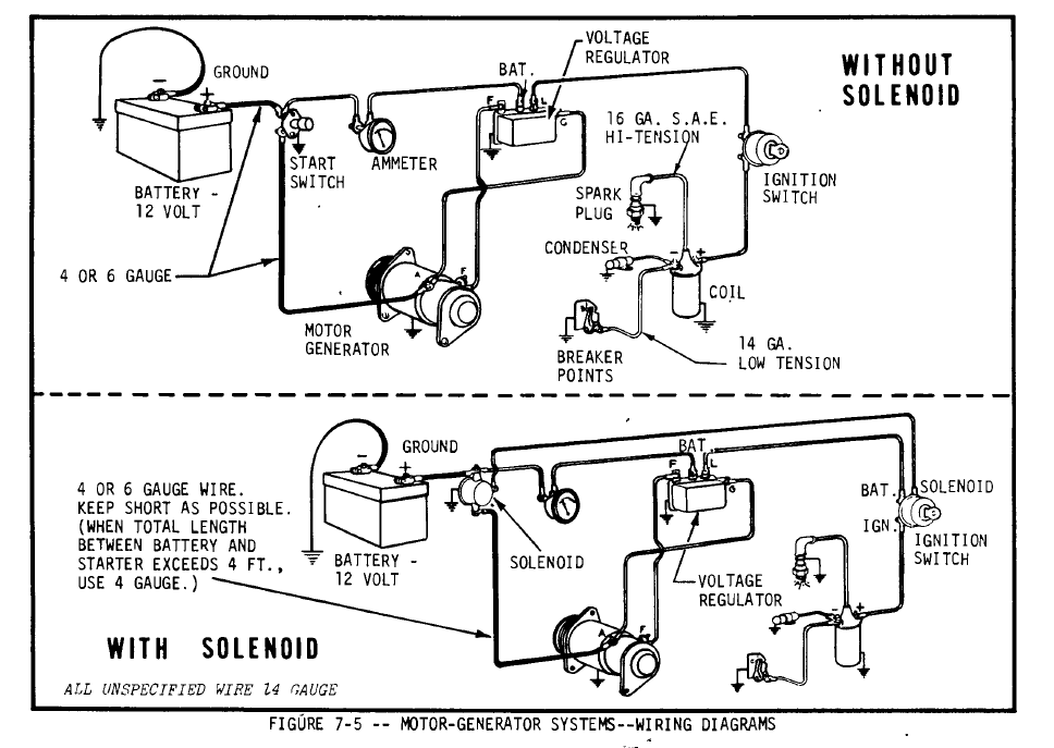
Each voltage regulator is a direct fit replacement that replaces oe damaged units providing accurate regulating charging voltage that the alternator produces. Wd wd45 with distributor 12 volt conversion coil napa echlin ic64sb 12 volt with an internal resistor. The corresponding terminal for the generator/alternator wire is marked an a or g (sometimes arm or gen). The pre 1970 mopar charging system diagram shows the basics of the early alternator / voltage regulator (vr) design. Tradenames and trademarks referred to within yesterday�s tractor co.
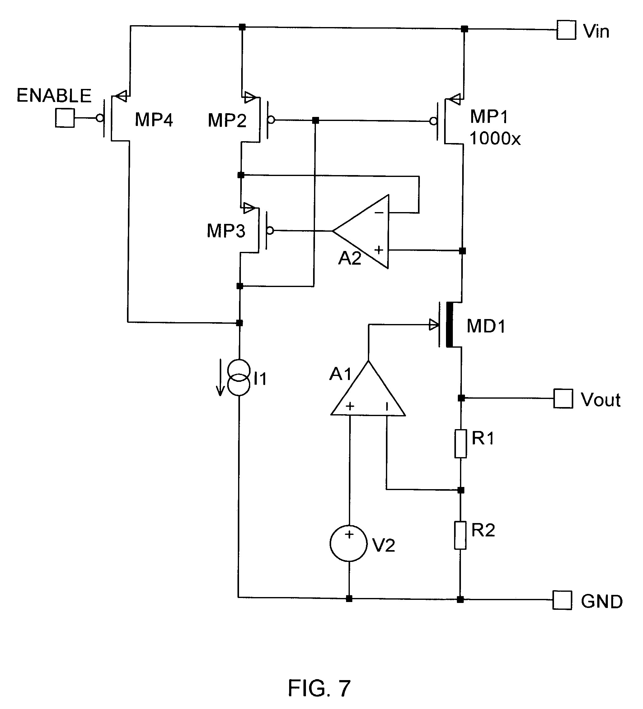 Source: mainetreasurechest.com
To do otherwise may cause excessively high or low voltage on the load side of the regulator or cause severe damage to the regulator.! Dvc 1 ohm sub wiring diagram; Lm117 is a reliable ic which can output regulated voltage in the range of 1.2 volts to 37 volts. Voltage 120 vac ( 90 ~ 140 vac) 1 phase 2 wire 50/60 hz output voltage 100 vdc @ 120 vac input current continuous 8a intermittent 10a for 10 sec resistance min. Napa (echlin) part numbers to compare your vr and coil:
 Source: in.pinterest.com
Just got an ic lm117 and 4 passive components. To do otherwise may cause excessively high or low voltage on the load side of the regulator or cause severe damage to the regulator.! E39 ignition switch wiring diagram; On the end of the harness is a plastic rectangular plug that has four colored wires attached. $ i�m trying to install a voltage regulator to my jeep cj5 where it�s never had one.
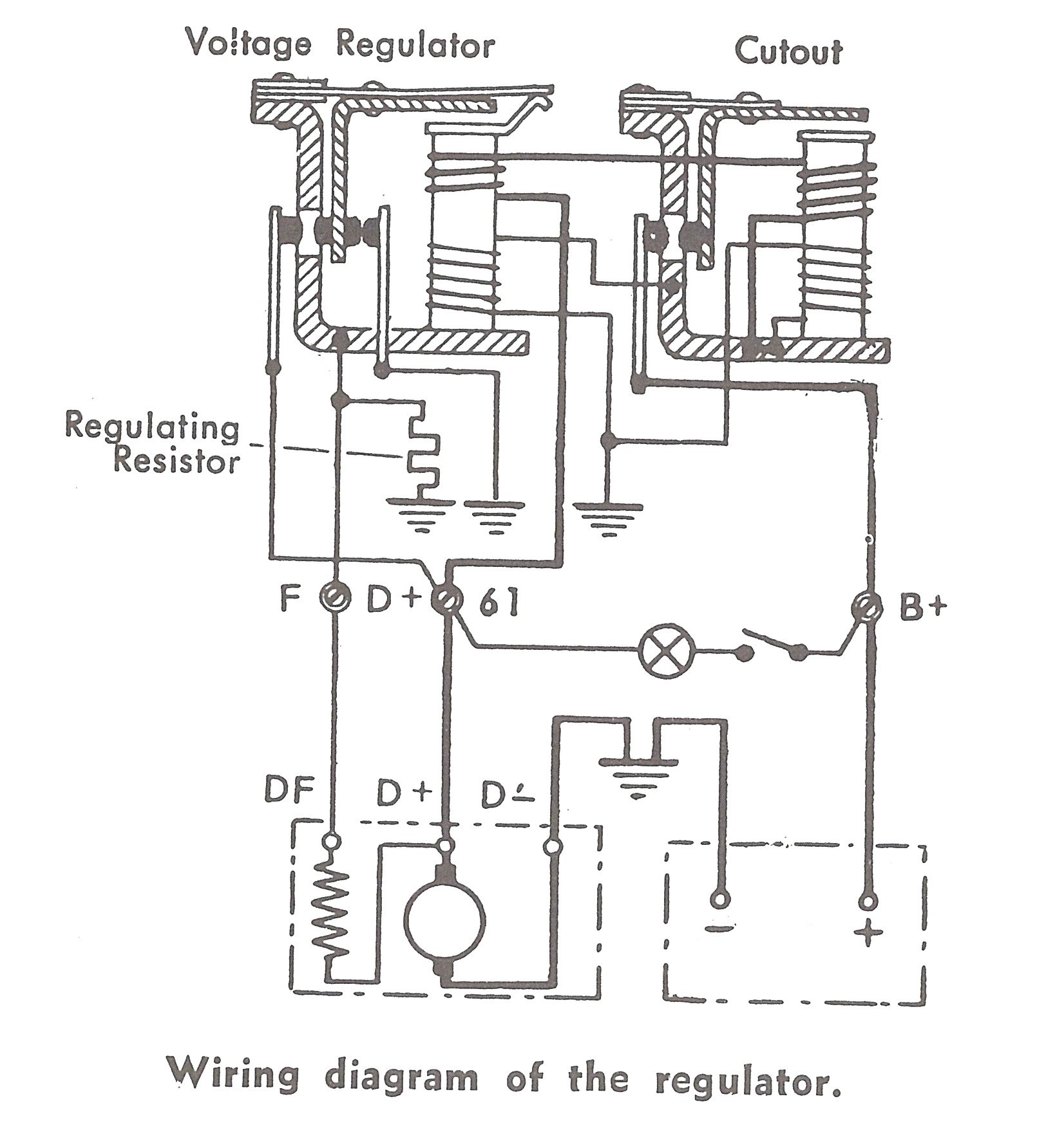 Source: mainetreasurechest.com
Wd wd45 with distributor 12 volt conversion coil napa echlin ic64sb 12 volt with an internal resistor. E39 ignition switch wiring diagram; Before we can hook up the circuit, let�s first go over the pinout diagram of the voltage regulator, which is vital for hooking up the circuit. Wd wd45 with distributor 12 volt conversion coil napa echlin ic64sb 12 volt with an internal resistor. Voltage regulator ford & new holland tractor brand new.
 Source: wiring89.blogspot.com
12 volt conversion wiring diagram wiring diagram is a simplified usual pictorial representation of an electrical circuit it shows the components of the circuit as simplified shapes and the skill and signal connections amongst the devices. Connect the generator or alternator wire to the regulator. Voltage regulator ford & new holland tractor brand new. Wires going into this alternator. On the end of the harness is a plastic rectangular plug that has four colored wires attached.
This site is an open community for users to do submittion their favorite wallpapers on the internet, all images or pictures in this website are for personal wallpaper use only, it is stricly prohibited to use this wallpaper for commercial purposes, if you are the author and find this image is shared without your permission, please kindly raise a DMCA report to Us.
If you find this site beneficial, please support us by sharing this posts to your preference social media accounts like Facebook, Instagram and so on or you can also bookmark this blog page with the title echlin voltage regulator wiring diagram by using Ctrl + D for devices a laptop with a Windows operating system or Command + D for laptops with an Apple operating system. If you use a smartphone, you can also use the drawer menu of the browser you are using. Whether it’s a Windows, Mac, iOS or Android operating system, you will still be able to bookmark this website.


