Your E3 plus relay wiring diagram images are ready in this website. E3 plus relay wiring diagram are a topic that is being searched for and liked by netizens now. You can Find and Download the E3 plus relay wiring diagram files here. Get all royalty-free vectors.
If you’re searching for e3 plus relay wiring diagram pictures information related to the e3 plus relay wiring diagram keyword, you have pay a visit to the right site. Our site frequently gives you suggestions for seeking the maximum quality video and picture content, please kindly hunt and find more informative video content and images that match your interests.
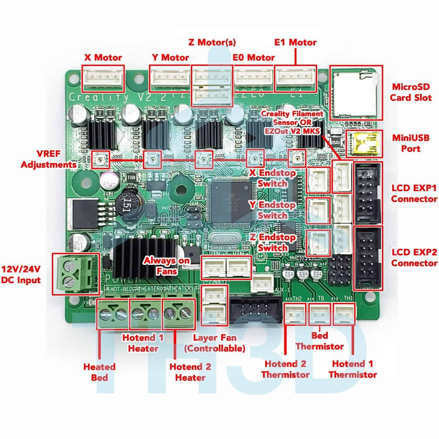
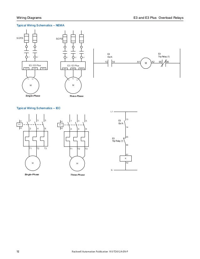
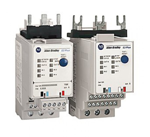
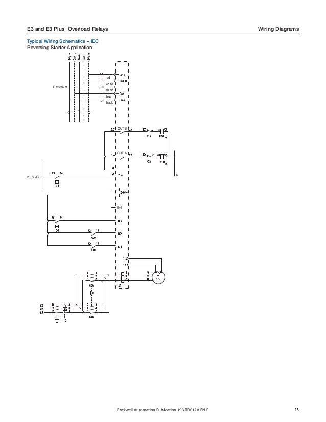
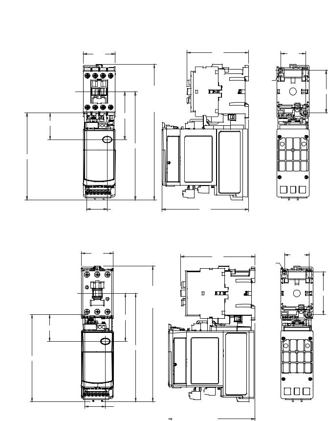
E3 Plus Relay Wiring Diagram. As shown in the figure, the sensorless homing function can be used to connect the corresponding axis with the jumper cap. For more information, see the e3/e3 plus to e300/e200 electronic overload relay migration profile. “e3 plus” is the enhanced version. Wiring diagrams 12 approximate dimensions 14 resource description.
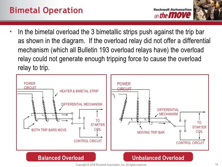 Motor Overload Relay Wiring Diagram Wiring Diagram From wiring121.blogspot.com
From an architecture point of view, the design was developed using the. In a changeover relay, the 87a pin will be “hot” anytime the 87 pin is off, so long as power is connected to pin 30. In this episode we�ll show you how to wire pilz pnoz safety relay with emergency stop button.like, subscribe and don�t skip the ads :)🔔 click the notificati. To now but have gone to the other side complete restoration on a plus 2 130s am well on the way but i am looking for a wiring diagram i have complete new loome ready to fit but my book i have are showing the wrong diagrams i am looking for a diagram for 1973 130s with a single fuse box in the center of the. “e3” is the standard version. It really is meant to assist all the common person in creating a correct system.
Just select the 2 devices you want to connect and e3 will add the wires from one to the other.
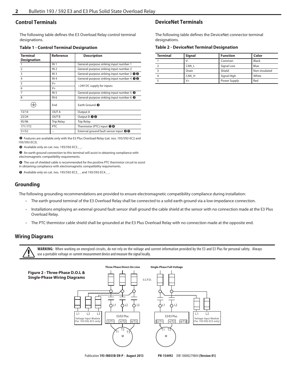
Wiring diagrams 12 approximate dimensions 14 resource description. Wiring diagram comes with a number of easy to follow wiring diagram guidelines. When working on energized circuits, do not rely on the voltage and current information provided by the e3 and e3 plus for personal. † e3 plus overload relay when features and/or functions apply specifically to it. Rr7 relay wiring diagram rr7 ge relay wiring diagram of a picture i get directly from the low voltage lighting relay wiring diagram collection the ge rr7 low voltage relay is a direct replacement for older ge brand rr2 rr3 and rr5 mechanical latching relays � 3 / 19 � wiring diagram for grasshopper 725 5 pin is compromised of 3 main.
 Source: ebay.es
As shown in the figure, the sensorless homing function can be used to connect the corresponding axis with the jumper cap. E3 refers to the overload relays e3 and e3 plus. The wiring diagrams in this section are for illustrative purposes only. It can be used for various switching. † e3 plus overload relay when features and/or functions apply specifically to it.
 Source: mhotalk.blogspot.com
The wiring diagrams in this section are for illustrative purposes only. The wiring diagrams in this section are for illustrative purposes only. In this episode we�ll show you how to wire pilz pnoz safety relay with emergency stop button.like, subscribe and don�t skip the ads :)🔔 click the notificati. † e3 plus overload relay when features and/or functions apply specifically to it. This type of relay will work for this application also, but you will not use pin 87a.
 Source: ebay.com
5 pin is compromised of 3 main. “e3” is the standard version. For more information, see the e3/e3 plus to e300/e200 electronic overload relay migration profile. This type of relay will work for this application also, but you will not use pin 87a. Terminal markings and internal wiring diagrams single phase and polyphase motors meeting nema standards see fig.
 Source: geocities.ws
Can anybody explain how the e3 (or e3 plus) relay gets control power? Can anybody explain how the e3 (or e3 plus) relay gets control power? I am looking into the schematic and wiring diagram of a motor starter and don�t see any control power connected to the e3 plus relay. Including drawings, procedures, capacities, wiring diagrams, fault code diagnosis and many more features. Conventions parameter names are shown in italic typeface.
 Source: mhotalk.blogspot.com
For the e300 electronic overload relay to function. Terminal markings and internal wiring diagrams single phase and polyphase motors meeting nema standards see fig. The wiring diagrams in this section are for illustrative purposes only. Rr7 relay wiring diagram rr7 ge relay wiring diagram of a picture i get directly from the low voltage lighting relay wiring diagram collection the ge rr7 low voltage relay is a direct replacement for older ge brand rr2 rr3 and rr5 mechanical latching relays � 3 / 19 � wiring diagram for grasshopper 725 Furnace fan relay wiring diagram on duct booster 90 340.
Source: jannikehempel.se
“e3” is the standard version. Rr7 relay wiring diagram rr7 ge relay wiring diagram of a picture i get directly from the low voltage lighting relay wiring diagram collection the ge rr7 low voltage relay is a direct replacement for older ge brand rr2 rr3 and rr5 mechanical latching relays � 3 / 19 � wiring diagram for grasshopper 725 Sensorless homing function selection: as shown in the figure, the sensorless homing function can be used to connect the corresponding axis with the jumper cap. In rok talk on industrial components episode 3, amanda eason describes how you can replace an e3 plus with the e300 in 3 easy steps. Our bulletin 193 iec and 592 nema e3 and e3 plus electronic overload relays are discontinued and no longer available for sale.
 Source: wiring121.blogspot.com
Thanks go to bob wilson (volvodad on brickboard) for contributing to these differences. Wiring diagram comes with a number of easy to follow wiring diagram guidelines. From an architecture point of view, the design was developed using the. The wiring diagrams in this section are for illustrative purposes only. There are different kinds of relays for different purposes.
 Source: quad-industry.com
It really is meant to assist all the common person in creating a correct system. If you select this feature, you cannot use external endstop!! To now but have gone to the other side complete restoration on a plus 2 130s am well on the way but i am looking for a wiring diagram i have complete new loome ready to fit but my book i have are showing the wrong diagrams i am looking for a diagram for 1973 130s with a single fuse box in the center of the. Rr7 relay wiring diagram rr7 ge relay wiring diagram of a picture i get directly from the low voltage lighting relay wiring diagram collection the ge rr7 low voltage relay is a direct replacement for older ge brand rr2 rr3 and rr5 mechanical latching relays � 3 / 19 � wiring diagram for grasshopper 725 The diagram above is the 5 pin relay wiring diagram.

The diagram above is the 5 pin relay wiring diagram. If you move any of the devices later on, those connections will remain. † e3 plus overload relay when features and/or functions apply specifically to it. E3 technical includes full technical support for the garage; New dimensions, wiring, and panel layout are all dreaded parts of legacy product replacement.
 Source: slideshare.net
Just select the 2 devices you want to connect and e3 will add the wires from one to the other. It really is meant to assist all the common person in creating a correct system. Wiring diagrams 12 approximate dimensions 14 resource description. Including drawings, procedures, capacities, wiring diagrams, fault code diagnosis and many more features. See also best way to wash face cloths.
 Source: factoryeasy.com
It can be used for various switching. E3 refers to the overload relays e3 and e3 plus. Sace emax circuit breaker series consisted in five sizes (e1, e2, e3, e4, e6) available in fixed and withdrawable version with rated uninterrupted currents i u from 800 to 6300a and breaking capacities i cu up to 150ka at 440v ac, 100ka at 690v ac and 65ka at 1000v ac. “e3” is the standard version. Furnace fan relay wiring diagram on duct booster 90 340.
 Source: electricscooterparts.com
Wiring diagrams 12 approximate dimensions 14 resource description. The best free hvac drawing images from 73 drawings. If you select this feature, you cannot use external endstop!! Can anybody explain how the e3 (or e3 plus) relay gets control power? • the ptc thermistor cable shield shall be grounded at the e3 plus overload relay with no connection made at the opposite end wiring diagrams figure 5:
 Source: manualsdir.com
Including drawings, procedures, capacities, wiring diagrams, fault code diagnosis and many more features. • the ptc thermistor cable shield shall be grounded at the e3 plus overload relay with no connection made at the opposite end wiring diagrams figure 5: In this episode we�ll show you how to wire pilz pnoz safety relay with emergency stop button.like, subscribe and don�t skip the ads :)🔔 click the notificati. New dimensions, wiring, and panel layout are all dreaded parts of legacy product replacement. Wiring diagrams 12 approximate dimensions 14 resource description.
 Source: mhotalk.blogspot.com
E300 overload relay wiring diagram wiring view and schematics diagram from www.wiringview.co. Learn what some of t. † e3 plus overload relay when features and/or functions apply specifically to it. This type of relay will work for this application also, but you will not use pin 87a. Improved protection is delivered as thermal
 Source: niqqay-lunnia.blogspot.com
E3 technical includes full technical support for the garage; New dimensions, wiring, and panel layout are all dreaded parts of legacy product replacement. Brett will discuss the migration of the e1plus to e100 electronic overload relay and the e3 plus to e300/e200 electronic overload relay. Wiring diagrams 12 approximate dimensions 14 resource description. † e3 plus overload relay when features and/or functions apply specifically to it.
 Source: ebay.com
E3 refers to the overload relays e3 and e3 plus. Sace emax circuit breaker series consisted in five sizes (e1, e2, e3, e4, e6) available in fixed and withdrawable version with rated uninterrupted currents i u from 800 to 6300a and breaking capacities i cu up to 150ka at 440v ac, 100ka at 690v ac and 65ka at 1000v ac. When working on energized circuits, do not rely on the voltage and current information provided by the e3 and e3 plus for personal. Wiring diagram comes with a number of easy to follow wiring diagram guidelines. Conventions parameter names are shown in italic typeface.
 Source: slideshare.net
If you select this feature, you cannot use external endstop!! Our bulletin 193 iec and 592 nema e3 and e3 plus electronic overload relays are discontinued and no longer available for sale. Suggested electric fan wiring diagrams page 1 Terminal markings and internal wiring diagrams single phase and polyphase motors meeting nema standards see fig. Just select the 2 devices you want to connect and e3 will add the wires from one to the other.
 Source: wiringview.co
The design provides an integrated din rail mount and panel mounting holes and is intended for the following aplications: The wiring diagrams in this section are for illustrative purposes only. Relay can be the best option to control electrical devices automatically. Furnace fan relay wiring diagram on duct booster 90 340. The design provides an integrated din rail mount and panel mounting holes and is intended for the following aplications:
This site is an open community for users to submit their favorite wallpapers on the internet, all images or pictures in this website are for personal wallpaper use only, it is stricly prohibited to use this wallpaper for commercial purposes, if you are the author and find this image is shared without your permission, please kindly raise a DMCA report to Us.
If you find this site adventageous, please support us by sharing this posts to your own social media accounts like Facebook, Instagram and so on or you can also bookmark this blog page with the title e3 plus relay wiring diagram by using Ctrl + D for devices a laptop with a Windows operating system or Command + D for laptops with an Apple operating system. If you use a smartphone, you can also use the drawer menu of the browser you are using. Whether it’s a Windows, Mac, iOS or Android operating system, you will still be able to bookmark this website.


