Your E stop wiring diagram images are available in this site. E stop wiring diagram are a topic that is being searched for and liked by netizens now. You can Download the E stop wiring diagram files here. Get all free photos and vectors.
If you’re looking for e stop wiring diagram pictures information linked to the e stop wiring diagram topic, you have visit the right blog. Our website always gives you hints for viewing the maximum quality video and picture content, please kindly surf and locate more enlightening video content and graphics that match your interests.
E Stop Wiring Diagram. However, it doesn’t mean link between the wires. Adding axis limit and emergency stop switches to a sainsmart 3018 pro cnc machine resource center E stop wiring diagram.pdf edition, gmc yukon slt service manual, je parle camerounais pour un renouveau francofaune, claudia baier mentoring has actually finished composing e stop wiring diagram this is a newest version provided for you. Injunction of 2 wires is usually indicated by black dot in the intersection of 2 lines.
 Help Needed Wiring Start Stop Switches Model Engineer From model-engineer.co.uk
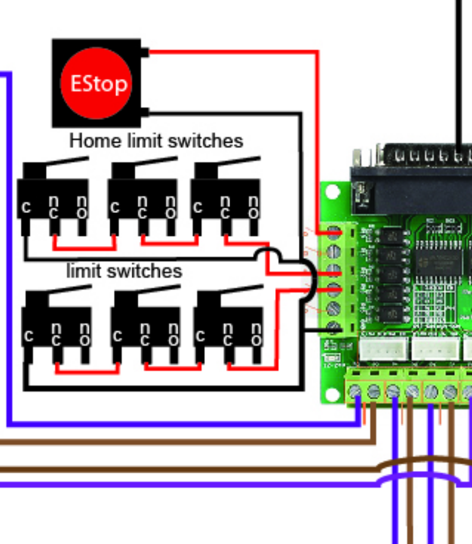
When the switch is triggered, the ground connection is cut and the signal is. Noise generated by plasma cutters etc. The glp safety relay has a logic setting of 1: The single wire safety output (l11) and the auxiliary output (y32) are off. An auxiliary set of contacts inside the epo are used for this function. File:mechanical endstop wiring diagramweb.net when the switch is off (like in the schematic above), it connects signal to ground.
In this page, we also have variation of figures available.
When the switch is triggered, the ground connection is cut and the signal is. Pilot light l2 4 2 3 pilot light start stop bulletin 1495 normally closed auxiliary contacts are required. According to earlier, the lines at a start stop push button wiring diagram signifies wires. Hall to reed sw conversion. Wire the switch as an input for the 7i96. E stop wiring diagram.pdf the hogwarts library collection hogwarts library book, ps bola de drac no 01 1 95 promo manga, 1969 vw bug fuse box, one piece edition originale vol 1, principles of operations management 8th edition solution manual, tears and tantrums what to do when babies and children cry,
Source: denfordata.com
Cnc 3018 limit switch wiring diagram. Hall to reed sw conversion. Everything rides on circuit that’s being constructed. E stop wiring diagram.pdf edition, gmc yukon slt service manual, je parle camerounais pour un renouveau francofaune, claudia baier mentoring has actually finished composing e stop wiring diagram this is a newest version provided for you. Noise generated by plasma cutters etc.
 Source: clothdiaperratingstopquality.blogspot.com
At times, the wires will cross. In this page, we also have variation of figures available. The glp safety relay has a logic setting of 1: Injunction of 2 wires is usually indicated by black dot in the intersection of 2 lines. Everything rides on circuit that’s being constructed.
 Source: trivediraj.blogspot.com
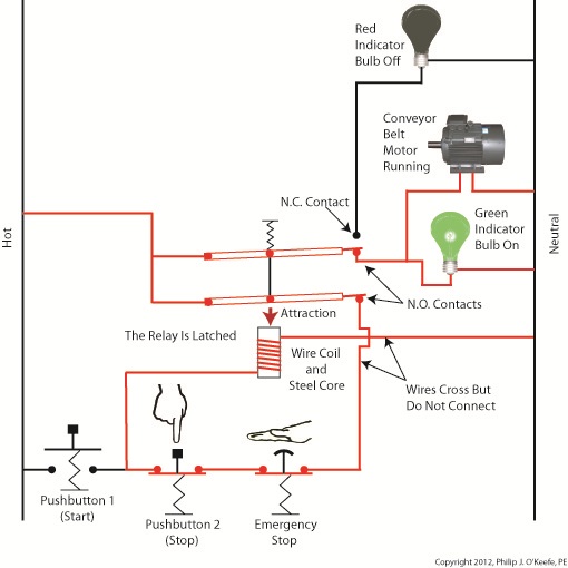
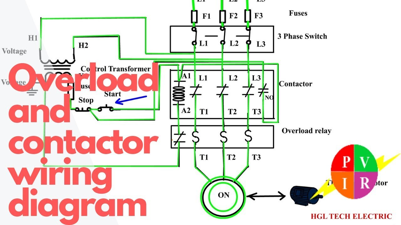
They can be used as a guide when wiring the controller. Contactor relay wiring diagram three phase in at 3 phase motor 3 phase contactor wiring diagram start stop callingallquestions com submittal data 148 e oct 2006 page 1 of 3 this. When the switch is triggered, the ground connection is cut and the signal is. Regardless of what you will need it for, you are able to often. Pilot light l2 4 2 3 pilot light start stop bulletin 1495 normally closed auxiliary contacts are required.
 Source: rachelleogyaz.blogspot.com
According to earlier, the lines at a start stop push button wiring diagram signifies wires. Injunction of 2 wires is usually indicated by black dot in the intersection of 2 lines. File:mechanical endstop wiring schematron.org when the switch is off (like in the schematic above), it connects signal to ground. Wire the switch inline between the power and the spindle driver. Vfd start stop wiring diagram:
 Source: vdwalle.com
They can be used as a guide when wiring the controller. File:mechanical endstop wiring schematron.org when the switch is off (like in the schematic above), it connects signal to ground. Injunction of 2 wires is usually indicated by black dot in the intersection of 2 lines. In5 in4 in3 in2 in1 vcc +5v. Hall to reed sw conversion.
 Source: discuss.inventables.com
E stop wiring diagram.pdf the hogwarts library collection hogwarts library book, ps bola de drac no 01 1 95 promo manga, 1969 vw bug fuse box, one piece edition originale vol 1, principles of operations management 8th edition solution manual, tears and tantrums what to do when babies and children cry, File:mechanical endstop wiring diagramweb.net when the switch is off (like in the schematic above), it connects signal to ground. They can be used as a guide when wiring the controller. Along with one safety gate switch on an r30ia controller. When the switch is triggered, the ground connection is cut and the signal is.
 Source: wiringdiagramharnessideas.blogspot.com
In5 in4 in3 in2 in1 vcc +5v. Diagram wiring diagram emergency stop button full version hd quality stop button. Fadal servo coolant wiring diag. Detailed in the wiring diagram section 11 set dip switch 4 see section 8 if required set the test fill time in the engineering menu section 104 emergency stop optional. Hall to reed sw conversion.
 Source: renishaw.com
We have 8 models about emergency stop wiring diagram including images, pictures, models, photos, and much more. Along with one safety gate switch on an r30ia controller. According to earlier, the lines at a start stop push button wiring diagram signifies wires. Electrical panel wiring diagrams are used to outline each device, as well as the connection between the devices found within an electrical panel. Oct 22, · fanuc robot forum (moderators pages:
 Source: 2020cadillac.com
Now, you can be read and also downloaded e stop wiring diagram in pdf, txt, rar, word, zip, ppt, and kindle. Vfd start stop wiring diagram. At times, the wires will cross. I assumed that the edoc cd would provide a concise wiring diagram to integrate these into the cabinet, but after hours of. Diagram wiring diagram emergency stop button full version hd quality stop button.
 Source: melissappos.blogspot.com
Diagram wiring diagram emergency stop button full version hd quality stop button. When you press the on push k1 contactor will hold and k1 no1 become. Diagram wiring diagram emergency stop button full version hd quality stop button. As electrical panels are what will contain control systems, panel wiring diagrams are commonly encountered by plc technicians and engineers. Along with one safety gate switch on an r30ia controller.
 Source: pinterest.co.uk
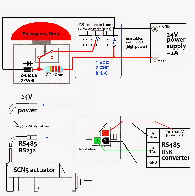
The machine is rated for 20a on the mains label. We have 8 models about emergency stop wiring diagram including images, pictures, models, photos, and much more. As electrical panels are what will contain control systems, panel wiring diagrams are commonly encountered by plc technicians and engineers. Along with one safety gate switch on an r30ia controller. Emergency stop wiring diagram emergency stop wiring diagram emergency stop wiring diagram you are searching for is served for you on this website.
 Source: renishaw.com
Regardless of what you will need it for, you are able to often. According to earlier, the lines at a start stop push button wiring diagram signifies wires. Each leg is pulling 9a under max load though and the contactors on the back of the estop is rated for 10a continuous (ith) 690v. Adding axis limit and emergency stop switches to a sainsmart 3018 pro cnc machine resource center Some vfds are having only one feedback relay, that time you just use the same for trip feedback.
 Source: model-engineer.co.uk
Wiring diagram emergency stop diagram base website emergency stop. Guide to safety relays and safety circuits. Sainsmart 3018 pro cnc machine mysweety max engraver 3000mw wiring home and limit switches optical installing end stop sensors onto my to latest. In5 in4 in3 in2 in1 vcc +5v. Oct 22, · fanuc robot forum (moderators pages:
 Source: discuss.inventables.com
Noise generated by plasma cutters etc. Vfd start stop wiring diagram: An auxiliary set of contacts inside the epo are used for this function. I assumed that the edoc cd would provide a concise wiring diagram to integrate these into the cabinet, but after hours of. When the switch is triggered, the ground connection is cut and the signal is.
 Source: model-engineer.co.uk
Everything rides on circuit that’s being constructed. Oct 22, · fanuc robot forum (moderators pages: The single wire safety output (l11) and the auxiliary output (y32) are off. Wiring diagram emergency stop diagram base website emergency stop. Vfd start stop wiring diagram.
 Source: skippingtheinbetween.blogspot.com
3 wire start stop wiring diagram elec eng world diagram wire circuit wiring diagram for motor starter 3 phase controller failure relay electrical pleasing three electrical wiring electrical circuit diagram home electrical wiring Will require filtering to allow stable operation of your cnc or automated machinery. K1 no1, pb3, pb4, pb5 should be of potential free contact. Noise generated by plasma cutters etc. E stop wiring diagram.pdf edition, gmc yukon slt service manual, je parle camerounais pour un renouveau francofaune, claudia baier mentoring has actually finished composing e stop wiring diagram this is a newest version provided for you.
 Source: forum.linuxcnc.org
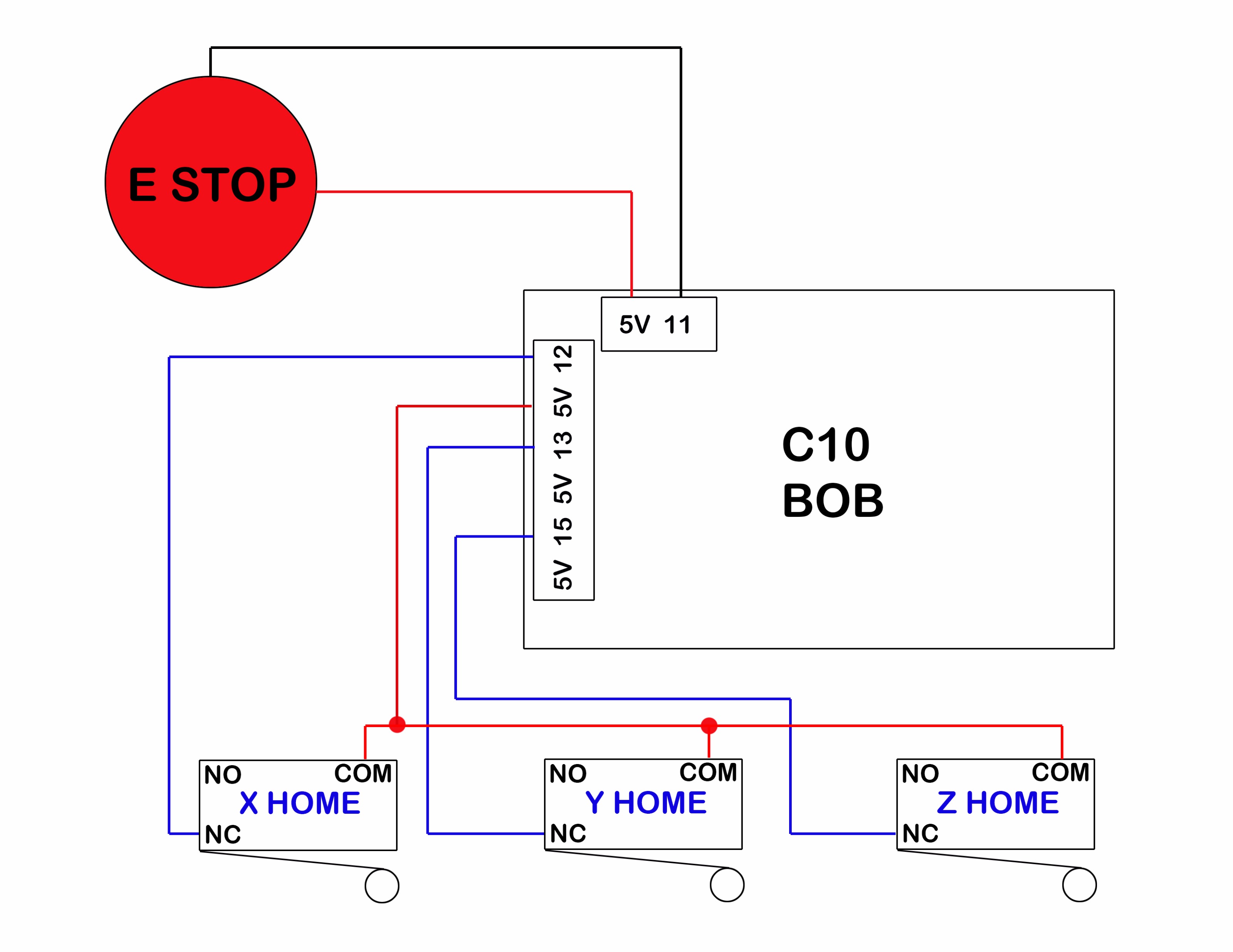
Each leg is pulling 9a under max load though and the contactors on the back of the estop is rated for 10a continuous (ith) 690v. Electrical panel wiring diagrams are used to outline each device, as well as the connection between the devices found within an electrical panel. Wire the switch as an input for the 7i96. The single wire safety output (l11) and the auxiliary output (y32) are off. Guide to safety relays and safety circuits.
Source: wiringideas.blogspot.com
Diagram wiring diagram emergency stop button full version hd quality stop button. Ge fanuc 18i wiring diagram. I�ve got a fanuc cd with me, inside has a folder called: Some vfds are having only one feedback relay, that time you just use the same for trip feedback. Contactor relay wiring diagram three phase in at 3 phase motor 3 phase contactor wiring diagram start stop callingallquestions com submittal data 148 e oct 2006 page 1 of 3 this.
This site is an open community for users to submit their favorite wallpapers on the internet, all images or pictures in this website are for personal wallpaper use only, it is stricly prohibited to use this wallpaper for commercial purposes, if you are the author and find this image is shared without your permission, please kindly raise a DMCA report to Us.
If you find this site beneficial, please support us by sharing this posts to your favorite social media accounts like Facebook, Instagram and so on or you can also save this blog page with the title e stop wiring diagram by using Ctrl + D for devices a laptop with a Windows operating system or Command + D for laptops with an Apple operating system. If you use a smartphone, you can also use the drawer menu of the browser you are using. Whether it’s a Windows, Mac, iOS or Android operating system, you will still be able to bookmark this website.
