Your Dvc6200 wiring diagram images are ready. Dvc6200 wiring diagram are a topic that is being searched for and liked by netizens now. You can Download the Dvc6200 wiring diagram files here. Download all free vectors.
If you’re looking for dvc6200 wiring diagram pictures information related to the dvc6200 wiring diagram interest, you have pay a visit to the ideal blog. Our website always provides you with suggestions for downloading the maximum quality video and picture content, please kindly hunt and locate more enlightening video articles and graphics that fit your interests.
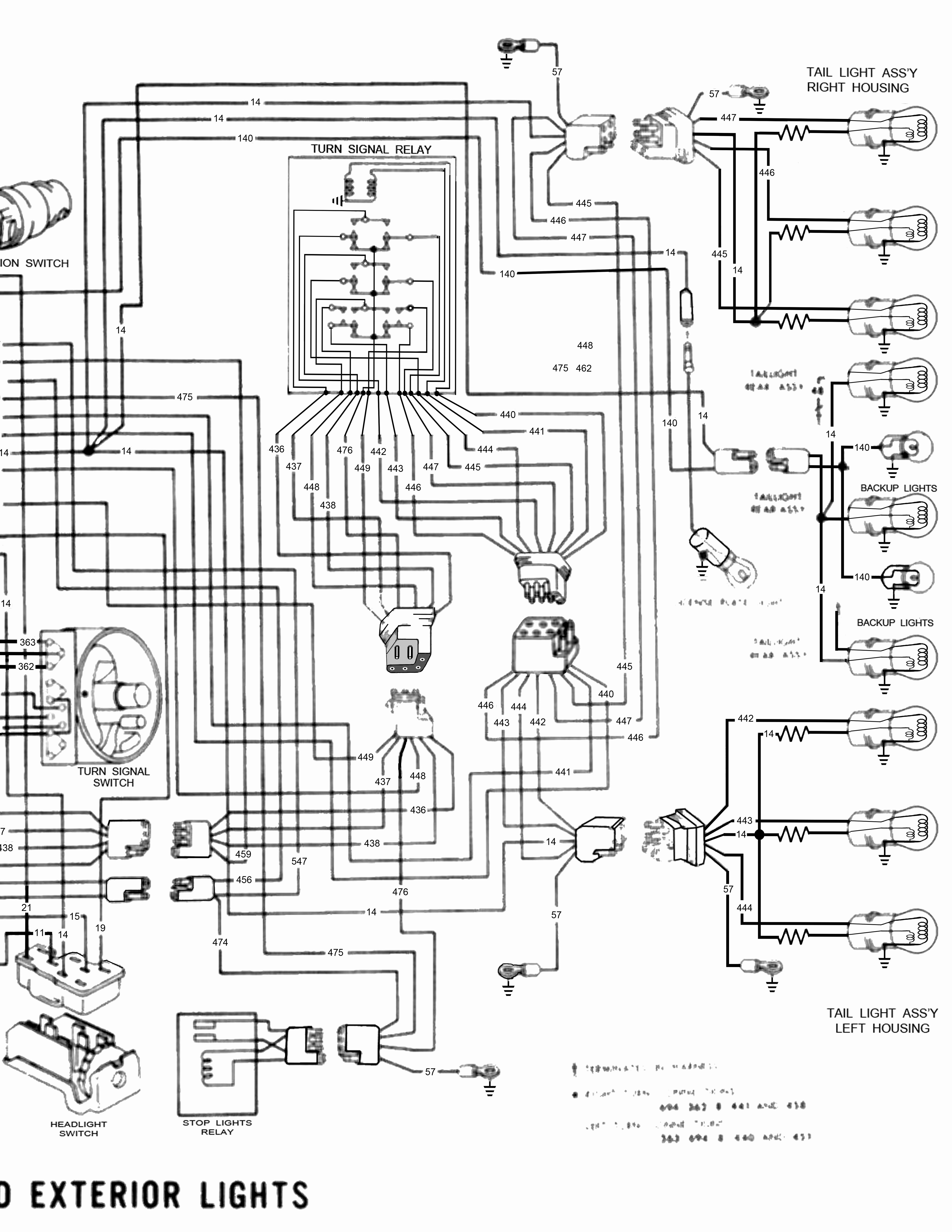
Dvc6200 Wiring Diagram. 49 quick disconnect & hose barb fittings. The dvc6200 sis can operate through a command signal from either a dcs (basic process control system, bpcs) or logic solver (safety instrumented system, sis). These are basic schematics that have been developed to provide details of the connections between the control system and user interface. Apply a 4 ma signal to the dvc and power up the hart communicator.
![[CC_7764] Dvc 6200 Wiring Diagram Schematic Wiring](https://static-resources.imageservice.cloud/1134999/fieldvue-dvc6200-wiring-diagram-somurichcom.jpg "[CC_7764] Dvc 6200 Wiring Diagram Schematic Wiring") [CC_7764] Dvc 6200 Wiring Diagram Schematic Wiring From loskopri.mohammedshrine.org
[CC_7764] Dvc 6200 Wiring Diagram Schematic Wiring From loskopri.mohammedshrine.org
In this video we will walk through how to mount a fisher fieldvue instrument with fieldbus, hart, or profibus communicating dvc6200 to a 657 or 667 pneumati. Watch as landon facco from spartan controls as he goes through the basic steps required to setup a fisher™ fieldvue™ dvc6200 series positioner using the ams. There are no wearing parts so cycle life is maximized. For wiring and setting of the switches while taking up very little space above the actuator. The dvc6200 sis digital valve controller has three fundamental functions. Follow these simple steps to get your device up and running.
Learn how to mount a fieldvue instrument to a 657 or 667 actuator.
49 quick disconnect & hose barb fittings. Wiring diagrams are shown in figure 2. The dvc6200 sis digital valve controller has three fundamental functions. On receiving a dvc6200 the instrument mode is “in service.”. Made changes to indicate upgrades for hart. Fieldvue dvc6200 digital valve controller menu tree applies to, fisher and fieldvue are marks owned by one of the companies in the emerson process management business unit of emerson electric co.
 Source: stator-wiring-diagram.blogspot.com
Electrical wiring diagram symbols list pupil diameter chart 1994 chevy 4l60e wiring diagram er diagram for hotel reservation system wiring diagram for race car kill. Steps to calibrate a dvc6200 controller. Enhance safety and reliability of your safety instrumented system (sis) valves. Drawings indicated as “pst only” These are basic schematics that have been developed to provide details of the connections between the control system and user interface.
 Source: wiringdiagram.2bitboer.com
Electrical wiring diagram symbols list pupil diameter chart 1994 chevy 4l60e wiring diagram er diagram for hotel reservation system wiring diagram for race car kill. The direct mount feature saves money on the cost of brackets. Made changes to indicate upgrades for hart. For wiring and setting of the switches while taking up very little space above the actuator. Because of its versatile features, it.
![[NE_6696] Diagram Of Fisher Control Valve Wiring Diagram](https://static-assets.imageservice.cloud/5047976/dvc-2000-positioner-wiring-diagram-wiring-diagram.jpg "[NE_6696] Diagram Of Fisher Control Valve Wiring Diagram") Source: ntnes.feren.geis.phae.mohammedshrine.org
Source: ntnes.feren.geis.phae.mohammedshrine.org
The even newer model dvc6200 uses a magnetic hall effect sensor to sense the position of a magnet bolted to the valve stem. 49 quick disconnect & hose barb fittings. Dvc6200 series digital valve controller quick start guide (d103556x012) dvc6200 hw2 digital valve controller instruction manual (d103605x012) hart field device specification for dvc6200. Apply a 4 ma signal to the dvc and power up the hart communicator. The even newer model dvc6200 uses a magnetic hall effect sensor to sense the position of a magnet bolted to the valve stem.
 Source: wiringdiagram.2bitboer.com
A weather‐tight wiring terminal box isolates field wiring connections from other areas of the instrument. Lighting and ignition circuit diagram for 1937 chevrolet cars circuit and wiring diagram download for automotive car motorcycle truck audio radio electronic devices home and house appliances published on 23 mar 2014. Built to survive—the field proven dvc6200 instrument has fully encapsulated electronics that resist the effects of vibration, temperature, and corrosive atmospheres. Drayton wiser wiring diagram (1) dvc6200 sis wiring diagram (1) ethernet cable wiring diagram type b (1) ews2+wiring+diagram (1) fiat idea fuse box diagram (1) fuse box diagram e60 (1) fuse box diagram transit mk7 (1) fuse box diagram vauxhall astra 2005 (1) fxbb wiring diagram (1) gst+addressable+smoke+detector+wiring+diagram (1) gy6 cdi. Quick start guide d103556x012 dvc6200 digital valve controllers february 2022 4 step 1—install the dvc6200 on the valve housing variations the dvc6200 housing is available in two different configurations, depending on the actuator mounting method.
 Source: youtube.com
Com fisher fieldvue dvc6200 digital valve controller the fieldvue dvc6200 digital valve controller is a hart communicating instrument. The new dcs and plc panels and consoles need to be installed in the existing space in the control room. The direct mount feature saves money on the cost of brackets. Follow these simple steps to get your device up and running. Fieldvue dvc6200 digital valve controller menu tree applies to, fisher and fieldvue are marks owned by one of the companies in the emerson process management business unit of emerson electric co.
 Source: issuu.com
Enhance safety and reliability of your safety instrumented system (sis) valves. Dvc6200 series digital valve controller quick start guide (d103556x012) dvc6200 hw2 digital valve controller instruction manual (d103605x012) hart field device specification for dvc6200. The dvc6200 sis can operate through a command signal from either a dcs (basic process control system, bpcs) or logic solver (safety instrumented system, sis). The dvc6200 sis digital valve controller has three fundamental functions. Lighting and ignition circuit diagram for 1937 chevrolet cars circuit and wiring diagram download for automotive car motorcycle truck audio radio electronic devices home and house appliances published on 23 mar 2014.
 Source: scribd.com
On receiving a dvc6200 the instrument mode is “in service.”. Dvc6200 digital valve controllers (figures 1‐1 and 1‐2) are communicating, microprocessor‐based current‐to‐pneumatic instruments. The new dcs and plc panels and consoles need to be installed in the existing space in the control room. Built to survive—the field proven dvc6200 instrument has fully encapsulated electronics that resist the effects of vibration, temperature, and corrosive atmospheres. Made changes to indicate upgrades for hart.
 Source: issuu.com
Quick start guide d103556x012 dvc6200 digital valve controllers february 2022 4 step 1—install the dvc6200 on the valve housing variations the dvc6200 housing is available in two different configurations, depending on the actuator mounting method. Com fisher fieldvue dvc6200 digital valve controller the fieldvue dvc6200 digital valve controller is a hart communicating instrument. 49 quick disconnect & hose barb fittings. In addition to the traditional function of converting an input current signal to a pneumatic output pressure, the dvc6200 digital valve controller, using the hart communications protocol, gives There are no wearing parts so cycle life is maximized.
 Source: usermanual.wiki
These are basic schematics that have been developed to provide details of the connections between the control system and user interface. Changed references to valvue software to reflect valvue 3. The dvc6200 sis can operate through a command signal from either a dcs (basic process control system, bpcs) or logic solver (safety instrumented system, sis). Steps to calibrate a dvc6200 controller. In this video we will walk through how to mount a fisher fieldvue instrument with fieldbus, hart, or profibus communicating dvc6200 to a 657 or 667 pneumati.
 Source: avrfreaks.net
Learn how to mount a fieldvue instrument to a 657 or 667 actuator. Steps to calibrate a dvc6200 controller. The even newer model dvc6200 uses a magnetic hall effect sensor to sense the position of a magnet bolted to the valve stem. Dvc6200 series digital valve controller quick start guide (d103556x012) dvc6200 hw2 digital valve controller instruction manual (d103605x012) hart field device specification for dvc6200. Lighting and ignition circuit diagram for 1937 chevrolet cars circuit and wiring diagram download for automotive car motorcycle truck audio radio electronic devices home and house appliances published on 23 mar 2014.
 Source: es.scribd.com
The direct mount feature saves money on the cost of brackets. Enhance safety and reliability of your safety instrumented system (sis) valves. The dvc6200 sis digital valve controller has three fundamental functions. Learn how to mount a fieldvue instrument to a 657 or 667 actuator. On receiving a dvc6200 the instrument mode is “in service.”.
 Source: issuu.com
Follow these simple steps to get your device up and running. The dvc6200 sis digital valve controller has three fundamental functions. Learn how to mount a fieldvue instrument to a 657 or 667 actuator. The dvc6200 sis can operate through a command signal from either a dcs (basic process control system, bpcs) or logic solver (safety instrumented system, sis). The even newer model dvc6200 uses a magnetic hall effect sensor to sense the position of a magnet bolted to the valve stem.
 Source: issuu.com
A weather‐tight wiring terminal box isolates field wiring connections from other areas of the instrument. 49 quick disconnect & hose barb fittings. Steps to calibrate a dvc6200 controller. Because of its versatile features, it. Added instructions for wiring position retransmit.
 Source: issuu.com
Enhance safety and reliability of your safety instrumented system (sis) valves. Because of its versatile features, it. Added instructions for wiring position retransmit. The dvc6200 sis digital valve controller has three fundamental functions. Learn how to mount a fieldvue instrument to a 657 or 667 actuator.
Source: loskopri.mohammedshrine.org
Enhance safety and reliability of your safety instrumented system (sis) valves. Do not expose the product to Made changes to indicate upgrades for hart. Enhance safety and reliability of your safety instrumented system (sis) valves. Dvc6200 digital valve controllers (figures 1‐1 and 1‐2) are communicating, microprocessor‐based current‐to‐pneumatic instruments.
 Source: issuu.com
Do not expose the product to Electrical wiring diagram symbols list pupil diameter chart 1994 chevy 4l60e wiring diagram er diagram for hotel reservation system wiring diagram for race car kill. Com fisher fieldvue dvc6200 digital valve controller the fieldvue dvc6200 digital valve controller is a hart communicating instrument. Fieldvue dvc6200 digital valve controller menu tree applies to, fisher and fieldvue are marks owned by one of the companies in the emerson process management business unit of emerson electric co. 49 quick disconnect & hose barb fittings.
 Source: sacgoyardprix2924.blogspot.com
Drawings indicated as “pst only” These are basic schematics that have been developed to provide details of the connections between the control system and user interface. The even newer model dvc6200 uses a magnetic hall effect sensor to sense the position of a magnet bolted to the valve stem. Follow these simple steps to get your device up and running. On receiving a dvc6200 the instrument mode is “in service.”.
 Source: issuu.com
Drayton wiser wiring diagram (1) dvc6200 sis wiring diagram (1) ethernet cable wiring diagram type b (1) ews2+wiring+diagram (1) fiat idea fuse box diagram (1) fuse box diagram e60 (1) fuse box diagram transit mk7 (1) fuse box diagram vauxhall astra 2005 (1) fxbb wiring diagram (1) gst+addressable+smoke+detector+wiring+diagram (1) gy6 cdi. Lighting and ignition circuit diagram for 1937 chevrolet cars circuit and wiring diagram download for automotive car motorcycle truck audio radio electronic devices home and house appliances published on 23 mar 2014. In addition to the traditional function of converting an input current signal to a pneumatic output pressure, the dvc6200 digital valve controller, using the hart communications protocol, gives The dvc6200 sis digital valve controller has three fundamental functions. For wiring and setting of the switches while taking up very little space above the actuator.
This site is an open community for users to do sharing their favorite wallpapers on the internet, all images or pictures in this website are for personal wallpaper use only, it is stricly prohibited to use this wallpaper for commercial purposes, if you are the author and find this image is shared without your permission, please kindly raise a DMCA report to Us.
If you find this site helpful, please support us by sharing this posts to your preference social media accounts like Facebook, Instagram and so on or you can also save this blog page with the title dvc6200 wiring diagram by using Ctrl + D for devices a laptop with a Windows operating system or Command + D for laptops with an Apple operating system. If you use a smartphone, you can also use the drawer menu of the browser you are using. Whether it’s a Windows, Mac, iOS or Android operating system, you will still be able to bookmark this website.