Your Dsc 4 wire smoke detector wiring diagram images are ready. Dsc 4 wire smoke detector wiring diagram are a topic that is being searched for and liked by netizens today. You can Download the Dsc 4 wire smoke detector wiring diagram files here. Get all free photos.
If you’re looking for dsc 4 wire smoke detector wiring diagram images information related to the dsc 4 wire smoke detector wiring diagram keyword, you have come to the ideal site. Our site always gives you hints for seeing the maximum quality video and image content, please kindly surf and find more informative video content and images that match your interests.
Dsc 4 Wire Smoke Detector Wiring Diagram. A two piece detector uses a base with a removable head. Since the company’s genesis, the experts at dsc have been leading the way. The wiring (cables) used for installation of the alarm system and accessories, shall be insulated with pvc, tfe, ptfe, fep, neoprene or polyamide. Fixed temperature and rate of rise
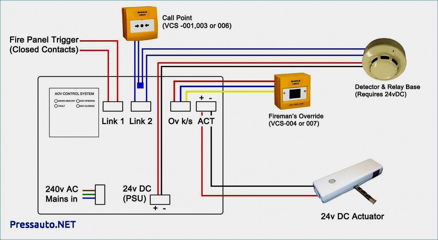 4 Wire Fire Alarm Wiring Diagram Wiring Diagram From wiringdiagram.2bitboer.com
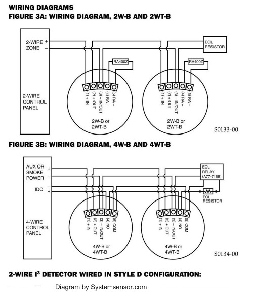
4 wire smoke detector</strong> zone can some extra steps, at least for the first such zone, since it requires you to do the regular zone programming as well as setting up a pgm for sensor reset. The alarm contact pair is a normally open contact, so your supervision resistor must be at the true end of the line. 4 wire smoke detector wiring diagram. The wiring (cables) used for installation of the alarm system and accessories, shall be insulated with pvc, tfe, ptfe, fep, neoprene or polyamide. Both positive wires are placed under the same terminal. Once the wiring has passed the last smoke detector, one lead of the resistor is connected in series with either one of the signal wires (in the diagram the resistor is on the no side) and the other lead from the resistor continues on to one side of the eol relay’s contacts.
(a) the equipment enclosure must be secured to the building structure before operation.
Follow the diagram and instructions provided by the smoke detector manufacturer, just to be sure. Both positive wires are placed under the same terminal. This instruction sheet is intended to be used with the installation manual of the alarm control panel. Series 65 optical smoke detector wiring diagram apollo smoke inside apollo smoke detectors series 65 wiring diagram image size 599 x 600 px. This will be set in system programmeing to open when the smoke detector reset command is keyed in. Since the company’s genesis, the experts at dsc have been leading the way.
 Source: home-security-systems-answers.com
A 4 wire smoke detector functions in a somewhat unique way compared to other hardwired devices. For details on connecting smoke detectors and other devices to a typical alarm panel, see ademco vista 20p wiring diagram. The sensor reset is needed to power down the smoke detectors for 5 seconds in case they go off wh Both positive wires are placed under the same terminal. Connect each wire to the 2 wire smoke terminals, as shown in the wiring diagram.

This instruction sheet is intended to be used with the installation manual of the alarm control panel. This will be set in system programmeing to open when the smoke detector reset command is keyed in. Both positive wires are placed under the same terminal. 4 wire smoke detectors can be pulled in a single run looping to each unit, just like 2 wire smokes. Each component should be set and linked to different parts in particular manner.
 Source: wiringview.co
Since the company’s genesis, the experts at dsc have been leading the way. (b) internal wiring must be. If a head is removed, the power opens. The sensor reset is needed to power down the smoke detectors for 5 seconds in case they go off wh Both positive wires are placed under the same terminal.
 Source: wiringview.co
The sensor reset is needed to power down the smoke detectors for 5 seconds in case they go off wh Size 216 h x 53 dia 55mm h x135mm dia weight 635 oz. If a head is removed, the power opens. A 4 wire smoke detector functions in a somewhat unique way compared to other hardwired devices. A hardwired smoke alarm installation involves wiring one of the smoke detectors (closest to the voltage source) to a 120 vac breaker in the main electric panel or tapping from a 120 v electrical box, wiring it using a 14/2 cable with a black (live), a white (neutral), and a ground wire, as shown by the diagram in figure 5.
 Source: schematron.org
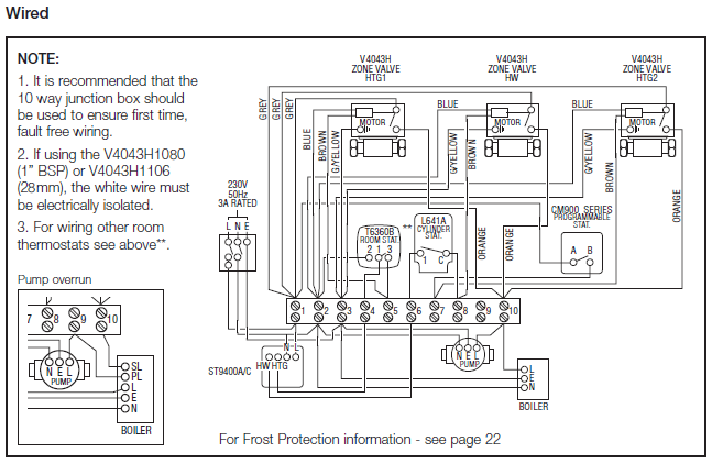
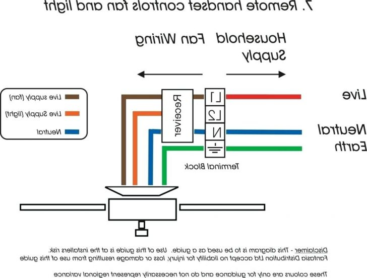
Wiring diagram also provides useful recommendations for tasks that may demand some additional gear. For specific details on how to connect wires to smoke detector screw terminals,. Follow the diagram and instructions provided by the smoke detector manufacturer, just to be sure. 15 19 14 3 20 1 3 alarm signal 2 aux. It consists of directions and diagrams for different kinds of wiring techniques and other things like lights, windows, etc.

Since the company’s genesis, the experts at dsc have been leading the way. Since the company’s genesis, the experts at dsc have been leading the way. Once the wiring has passed the last smoke detector, one lead of the resistor is connected in series with either one of the signal wires (in the diagram the resistor is on the no side) and the other lead from the resistor continues on to one side of the eol relay’s contacts. 12v power for the smokes must pass through a normally closed contact on your relay module. This instruction sheet is intended to be used with the installation manual of the alarm control panel.

(a) the equipment enclosure must be secured to the building structure before operation. For specific details on how to connect wires to smoke detector screw terminals,. Since the company’s genesis, the experts at dsc have been leading the way. You�re gonna put it under the alarm relay. A wiring diagram is a schematic type that uses abstract illustrated symbols to show all of the components of a system.
 Source: wiringdiagram.2bitboer.com
A two piece detector uses a base with a removable head. The following rules must be followed when wiring the keybus: This instruction sheet is intended to be used with the installation manual of the alarm control panel. Once the wiring has passed the last smoke detector, one lead of the resistor is connected in series with either one of the signal wires (in the diagram the resistor is on the no side) and the other lead from the resistor continues on to one side of the eol relay’s contacts. Connect each wire to the 2 wire smoke terminals, as shown in the wiring diagram.
 Source: wiringdiagram.2bitboer.com
4 wire smoke detector</strong> zone can some extra steps, at least for the first such zone, since it requires you to do the regular zone programming as well as setting up a pgm for sensor reset. Many 4 wire smoke detectors are designed so the wiring can connect to the terminals from either direction. A two piece detector uses a base with a removable head. Connect each wire to the 2 wire smoke terminals, as shown in the wiring diagram. Alarm (red led) power (green led) common dh100acdclp.
 Source: diagramweb.net
Do not place links between the wiring positions of terminals 2 and 5 to provide power supervision. Follow the diagram and instructions provided by the smoke detector manufacturer, just to be sure. Do not place links between the wiring positions of terminals 2 and 5 to provide power supervision. This will be set in system programmeing to open when the smoke detector reset command is keyed in. Wiring diagram shown is for dh100acdclp 4 wire duct smoke detector system equipped without a control panel.
 Source: schematron.org
The following rules must be followed when wiring the keybus: For details on connecting smoke detectors and other devices to a typical alarm panel, see ademco vista 20p wiring diagram. A hardwired smoke alarm installation involves wiring one of the smoke detectors (closest to the voltage source) to a 120 vac breaker in the main electric panel or tapping from a 120 v electrical box, wiring it using a 14/2 cable with a black (live), a white (neutral), and a ground wire, as shown by the diagram in figure 5. Once the wiring has passed the last smoke detector, one lead of the resistor is connected in series with either one of the signal wires (in the diagram the resistor is on the no side) and the other lead from the resistor continues on to one side of the eol relay’s contacts. 15 19 14 3 20 1 3 alarm signal 2 aux.
 Source: help.konnected.io
For specific details on how to connect wires to smoke detector screw terminals,. Series 65 optical smoke detector wiring diagram apollo smoke inside apollo smoke detectors series 65 wiring diagram image size 599 x 600 px. Do not place links between the wiring positions of terminals 2 and 5 to provide power supervision. Once the wiring has passed the last smoke detector, one lead of the resistor is connected in series with either one of the signal wires (in the diagram the resistor is on the no side) and the other lead from the resistor continues on to one side of the eol relay’s contacts. Alarm (red led) power (green led) common dh100acdclp.
 Source: jumpstarterdiscount.blogspot.com
You�re gonna put it under the alarm relay. 12v power for the smokes must pass through a normally closed contact on your relay module. And you�re not gonna put this on the power wires. Do not place links between the wiring positions of terminals 2 and 5 to provide power supervision. 4 wire smoke detector</strong> zone can some extra steps, at least for the first such zone, since it requires you to do the regular zone programming as well as setting up a pgm for sensor reset.
 Source: wiringdiagramall.blogspot.com
A 4 wire smoke detector functions in a somewhat unique way compared to other hardwired devices. You�re gonna put it under the alarm relay. Many 4 wire smoke detectors are designed so the wiring can connect to the terminals from either direction. The sensor reset is needed to power down the smoke detectors for 5 seconds in case they go off wh Wiring diagram also provides useful recommendations for tasks that may demand some additional gear.
![[DIAGRAM] Dsc Diagram 4 Wire Smoke Detector Installation [DIAGRAM] Dsc Diagram 4 Wire Smoke Detector Installation](https://desbennettconsultants.netlify.app/img/placeholder.svg)
Each component should be set and linked to different parts in particular manner. Since the company’s genesis, the experts at dsc have been leading the way. And you�re not gonna put this on the power wires. The following rules must be followed when wiring the keybus: Begin pulling from the main alarm panel location, past each smoke detector along the way, until the last smoke is reached.
 Source: pinterest.com
For specific details on how to connect wires to smoke detector screw terminals, have a look at smoke detector circuit basics.4 wire smoke detector on dsc systemalarmsbc presents fire alarm equipment heat detector smoke detectors Running 4 wire smoke detectors. Follow the diagram and instructions provided by the smoke detector manufacturer, just to be sure. Fixed temperature and rate of rise Do not place links between the wiring positions of terminals 2 and 5 to provide power supervision.
 Source: diagramweb.net
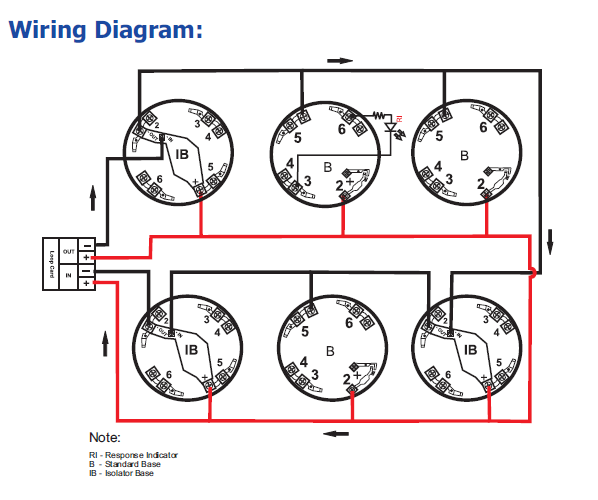
Series 65 optical smoke detector wiring diagram apollo smoke inside apollo smoke detectors series 65 wiring diagram image size 599 x 600 px. Many 4 wire smoke detectors are designed so the wiring can connect to the terminals from either direction. Series 65 optical smoke detector wiring diagram apollo smoke inside apollo smoke detectors series 65 wiring diagram image size 599 x 600 px. The wiring (cables) used for installation of the alarm system and accessories, shall be insulated with pvc, tfe, ptfe, fep, neoprene or polyamide. For details on connecting smoke detectors and other devices to a typical alarm panel, see ademco vista 20p wiring diagram.
 Source: wiringdiagram.2bitboer.com
4 wire smoke detector</strong> zone can some extra steps, at least for the first such zone, since it requires you to do the regular zone programming as well as setting up a pgm for sensor reset. A 4 wire smoke detector functions in a somewhat unique way compared to other hardwired devices. The alarm contact pair is a normally open contact, so your supervision resistor must be at the true end of the line. For specific details on how to connect wires to smoke detector screw terminals,. Do not place links between the wiring positions of terminals 2 and 5 to provide power supervision.
This site is an open community for users to share their favorite wallpapers on the internet, all images or pictures in this website are for personal wallpaper use only, it is stricly prohibited to use this wallpaper for commercial purposes, if you are the author and find this image is shared without your permission, please kindly raise a DMCA report to Us.
If you find this site good, please support us by sharing this posts to your preference social media accounts like Facebook, Instagram and so on or you can also bookmark this blog page with the title dsc 4 wire smoke detector wiring diagram by using Ctrl + D for devices a laptop with a Windows operating system or Command + D for laptops with an Apple operating system. If you use a smartphone, you can also use the drawer menu of the browser you are using. Whether it’s a Windows, Mac, iOS or Android operating system, you will still be able to bookmark this website.


