Your Drive isolation transformer wiring diagram images are ready in this website. Drive isolation transformer wiring diagram are a topic that is being searched for and liked by netizens now. You can Find and Download the Drive isolation transformer wiring diagram files here. Find and Download all royalty-free photos and vectors.
If you’re searching for drive isolation transformer wiring diagram pictures information connected with to the drive isolation transformer wiring diagram keyword, you have pay a visit to the right blog. Our website always provides you with hints for refferencing the maximum quality video and picture content, please kindly hunt and locate more enlightening video articles and images that fit your interests.
Drive Isolation Transformer Wiring Diagram. First start the isolation transformer without load to observe and test whether the input and output voltages meet the requirements. An isolating transformer eliminates the galvanic currents, and thus protect propellers and propeller shafts from corrosion. Drive isolation transformer wiring diagram. F or w * case style:
 Current Transducer Wiring Diagram Gallery From wholefoodsonabudget.com
Mechanical stresses found in today’s ac & dc motor drives. Isolation transformer wiring diagram onan pmg wiring diagram. The inherent excellent line isolation of these transformers is further enhanced with the extra protection of acme’s electrostatic shield — free in all dit’s. In the diagram above, taking an installation without an isolation transformer, the device has an earth fault (for example a live conductor has shorted to the chassis). Hps offers two lines of drive isolation transformers compliant to different levels of efficiency. Es is the secondary voltage.
Complete line of motor drive isolation transformers.
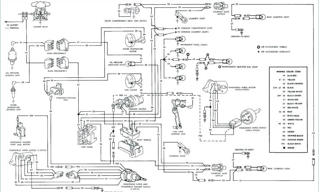
All the transformers in this section are rated for both 50 and 60 hz, for use worldwide. 3 phase isolation transformer wiring diagram what is a wiring diagram. The ground wire is connected to the transformer housing (if the transformer has a case, it should be connected to the ground wire of the case). Use the “find a product” tool on our website for detailed specification sheets. A wiring diagram is a simple visual representation with the physical connections and physical layout of your electrical system or circuit. All the transformers in this section are rated for both 50 and 60 hz, for use worldwide.
 Source: southernelectronicservices.com.au
Lr3902 frequency 60 hz 60 hz insulation system 220°c (150°c rise) 200°c (130°c rise) on some copper units up to 40kva 220°c (150°c rise) (optional 115°c and 80°c rise available) A wiring diagram is a simplified standard pictorial depiction of an electrical circuit. Mechanical stresses found in today’s ac & dc motor drives. Wiring diagram of isolation transformer. F or w * case style:
 Source: electricalacademia.com
Wiring an isolation transformer i found a pristine never been used topaz square d company 91018 31 18 kva ultra isolator line. Transformer grounding and bonding diagram. Where, ep is the primary voltage. The complete family of transformers from ge provide quiet, reliable transformer operation. Since neutral and earth are bonded in the consumer unit the system sees this as a short circuit and so a large current will flow which will blow the fuse or trip a circuit breaker.
 Source: multisim.com
I�ve attached a couple of pictures of the wiring diagrams as i think they should go. Isolation transformer wiring diagram onan pmg wiring diagram. Transformer sizes offered from 3 to 330 kva. Where, ep is the primary voltage. Kva 5 7.5 7.5 11 10 14 15 20 20 27 25 34 30 40 40 51 50 63 60 75 motor transformer h.p.
 Source: e2e.ti.com
Use of a solidly grounded drive isolation transformer to reroute i scientific diagram. Kva 75 93 100 118 125 145 150 175 200 220 • amps/kva calculator • wiring diagram selector. Assortment of 3 phase isolation transformer wiring diagram. Isolation transformer wiring diagram onan pmg wiring diagram.
 Source: respuestas.me
How to wire install isolation transformer ato com transformers provide galvanic digikey electrical4u what is an and are its advantages instrumentation control engineering you. Lower losses the harmonic currents generated by ac & dc drives increase eddy current losses (heat) in transformer windings. The transformer must also provide a voltage change to match the required voltage of the scr drive. Ground wire, used for protection. Dimensions (wxdxh) 26.00 x 25.00 x 38.00 :
 Source: analog.com
Use the “find a product” tool on our website for detailed specification sheets. Since neutral and earth are bonded in the consumer unit the system sees this as a short circuit and so a large current will flow which will blow the fuse or trip a circuit breaker. The complete family of transformers from ge provide quiet, reliable transformer operation. Dimensions (wxdxh) 26.00 x 25.00 x 38.00 : Kva 75 93 100 118 125 145 150 175 200 220
 Source: lcmagnetics.com
Primary and secondary windings are wound on a common ferromagnetic core. Isolation transformers, to begin with, are transformers, and they share the common characteristics of transformers (figure 1). Transformer grounding and bonding diagram. A wiring diagram is a simple visual representation with the physical connections and physical layout of your electrical system or circuit. Drive isolation transformers 7.5 to 175 kva 220 to 660 kva ul listed file:
Source: wholefoodsonabudget.com
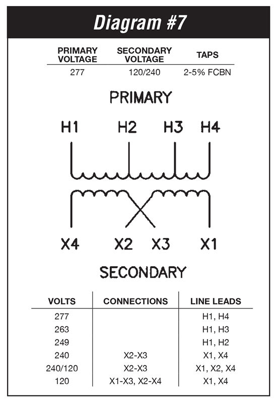
Lr3902 frequency 60 hz 60 hz insulation system 220°c (150°c rise) 200°c (130°c rise) on some copper units up to 40kva 220°c (150°c rise) (optional 115°c and 80°c rise available) Purpose of shielded isolation transformer. Scroll to continue with content. The transformer must also provide a voltage change to match the required voltage of the scr drive. Ep(volts) es(volts) = n p n s e p ( v o l t s) e s ( v o l t s) = n p n s.
 Source: e2e.ti.com
Drive isolation transformers are sized to match standard motor horsepower and voltage ratings. All the transformers in this section are rated for both 50 and 60 hz, for use worldwide. See local codes regarding safety requirements. Drive isolation transformers 7.5 to 175 kva 220 to 660 kva ul listed file: The difficulty in point of fact is that all car is different.
 Source: electronics.stackexchange.com
In the diagram above, taking an installation without an isolation transformer, the device has an earth fault (for example a live conductor has shorted to the chassis). The schematic of a simple power transformer consisting of a primary winding of n p turns and a secondary winding of n s turns on a. Hps offers two lines of drive isolation transformers compliant to different levels of efficiency. Scroll to continue with content. In the diagram above, taking an installation without an isolation transformer, the device has an earth fault (for example a live conductor has shorted to the chassis).
 Source: ato.com
The ground wire is connected to the transformer housing (if the transformer has a case, it should be connected to the ground wire of the case). I�ve attached a couple of pictures of the wiring diagrams as i think they should go. Since neutral and earth are bonded in the consumer unit the system sees this as a short circuit and so a large current will flow which will blow the fuse or trip a circuit breaker. Primary and secondary windings are wound on a common ferromagnetic core. Dimensions (wxdxh) 26.00 x 25.00 x 38.00 :
 Source: electronics.stackexchange.com
Primary and secondary windings are wound on a common ferromagnetic core. Isolation transformer wiring diagram onan pmg wiring diagram. Hps offers two lines of drive isolation transformers compliant to different levels of efficiency. Isolation transformers, to begin with, are transformers, and they share the common characteristics of transformers (figure 1). The transformer must also provide a voltage change to match the required voltage of the scr drive.
 Source: favreadblogs.blogspot.com
Dimensions (wxdxh) 26.00 x 25.00 x 38.00 : Our standard transformer range covers 10, 16, 32, 50, 63 & 100 amp single phase shore capacities at 230v. Dry type drive isolation transformer too hot electric power transmission distribution eng tips. 3 phase isolation transformer wiring diagram what is a wiring diagram. Lr3902 frequency 60 hz 60 hz insulation system 220°c (150°c rise) 200°c (130°c rise) on some copper units up to 40kva 220°c (150°c rise) (optional 115°c and 80°c rise available)
 Source: leadacidbatterydesulfation.yuku.com
Wiring diagram line we are make source the schematics, wiring diagrams and technical photos. Hps offers two lines of drive isolation transformers compliant to different levels of efficiency. Kva 5 7.5 7.5 11 10 14 15 20 20 27 25 34 30 40 40 51 50 63 60 75 motor transformer h.p. First start the isolation transformer without load to observe and test whether the input and output voltages meet the requirements. Lower losses the harmonic currents generated by ac & dc drives increase eddy current losses (heat) in transformer windings.
 Source: seekic.com
Purpose of shielded isolation transformer. The ground wire is connected to the transformer housing (if the transformer has a case, it should be connected to the ground wire of the case). Lr3902 frequency 60 hz 60 hz insulation system 220°c (150°c rise) 200°c (130°c rise) on some copper units up to 40kva 220°c (150°c rise) (optional 115°c and 80°c rise available) Wiring diagram line we are make source the schematics, wiring diagrams and technical photos. The transformer must also provide a voltage change to match the required voltage of the scr drive.
 Source: e2e.ti.com
Complete line of motor drive isolation transformers. Drive isolation transformers 7.5 to 175 kva 220 to 660 kva ul listed file: A wiring diagram is a simplified standard pictorial depiction of an electrical circuit. Lr3902 frequency 60 hz 60 hz insulation system 220°c (150°c rise) 200°c (130°c rise) on some copper units up to 40kva 220°c (150°c rise) (optional 115°c and 80°c rise available) In the same way as a pain to remove, replace or repair the wiring in an automobile, having an accurate and detailed.
 Source: e2e.ti.com
The ground wire is connected to the transformer housing (if the transformer has a case, it should be connected to the ground wire of the case). Drive isolation transformers 7.5 to 175 kva 220 to 660 kva ul listed file: Ep(volts) es(volts) = n p n s e p ( v o l t s) e s ( v o l t s) = n p n s. Component isolation transformer circuit diagram the power mosfet isolated gate drive basic wiring. A wiring diagram is a simple visual representation with the physical connections and physical layout of your electrical system or circuit.
 Source: elexstudy.blogspot.com
The schematic of a simple power transformer consisting of a primary winding of n p turns and a secondary winding of n s turns on a. Since neutral and earth are bonded in the consumer unit the system sees this as a short circuit and so a large current will flow which will blow the fuse or trip a circuit breaker. Use the “find a product” tool on our website for detailed specification sheets. We provide energy efficient solutions that help. Es is the secondary voltage.
This site is an open community for users to share their favorite wallpapers on the internet, all images or pictures in this website are for personal wallpaper use only, it is stricly prohibited to use this wallpaper for commercial purposes, if you are the author and find this image is shared without your permission, please kindly raise a DMCA report to Us.
If you find this site serviceableness, please support us by sharing this posts to your own social media accounts like Facebook, Instagram and so on or you can also bookmark this blog page with the title drive isolation transformer wiring diagram by using Ctrl + D for devices a laptop with a Windows operating system or Command + D for laptops with an Apple operating system. If you use a smartphone, you can also use the drawer menu of the browser you are using. Whether it’s a Windows, Mac, iOS or Android operating system, you will still be able to bookmark this website.