Your Dmx wiring diagram images are available. Dmx wiring diagram are a topic that is being searched for and liked by netizens now. You can Get the Dmx wiring diagram files here. Download all royalty-free images.
If you’re looking for dmx wiring diagram pictures information linked to the dmx wiring diagram keyword, you have visit the ideal blog. Our website always provides you with suggestions for seeking the maximum quality video and image content, please kindly surf and find more informative video content and graphics that match your interests.
Dmx Wiring Diagram. The trouble in fact is that all car is different. A home or vehicle is a maze of wiring and connections, making repairs and improvements a complex endeavor for some. Let’s say you have 4 led fixtures. Dmx is a protocol founded in the theatre lighting industry and is often specified when a large amount of colour changing fittings need to be controlled simultaneously.
 Usb To Dmx Wiring Diagram USB Wiring Diagram From usbwiringdiagram.com
And show address via digital numueric display. Data + (pair 1 true) 3. Utp cat5 or cat6 network cable is another option but it has a slightly lower impedance of 100ω Let’s say you have 4 led fixtures. Dmx cables are most commonly made with 2 core shielded data cable terminated at either end with 3 or 5 pin xlr connectors (one male, one female). 4 channels per dot rgb:
Constant current dmx decoder px707 4 channels 200 1600ma per channel the current of each channel can be set separately dmx led controller constant current.
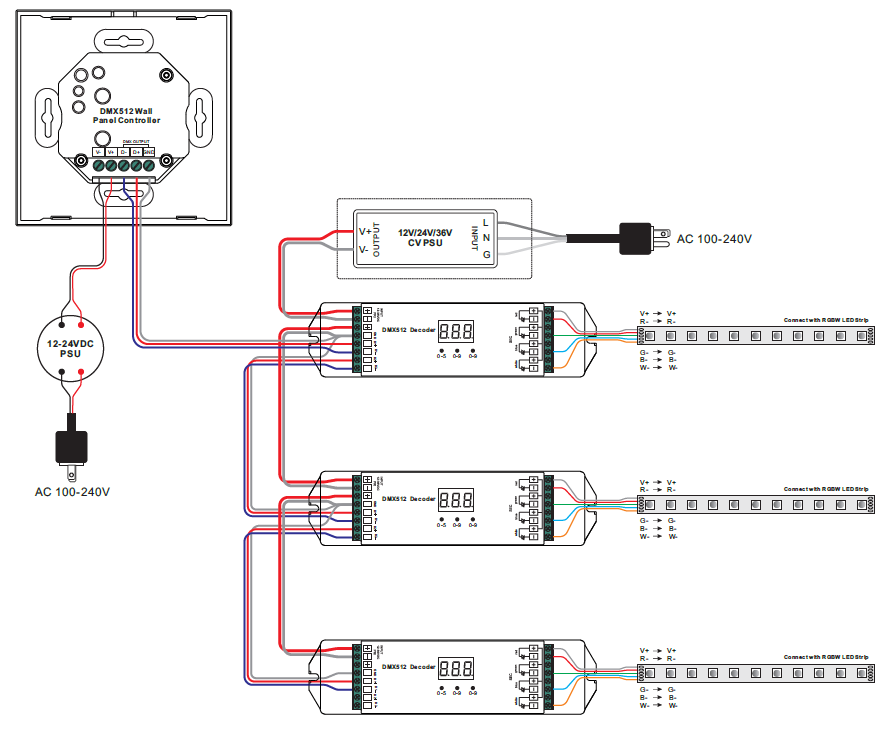
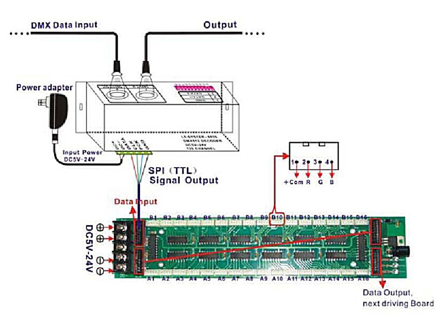
4 channels per dot rgb: Constant current dmx decoder px707 4 channels 200 1600ma per channel the current of each channel can be set separately dmx led controller constant current. Taking into consideration trying to remove, replace or repair the wiring in an automobile, having an accurate and detailed dmx lighting wiring. Easy dmx512 decoder feature standard dmx512 compliant control interface, enable to set the dmx address freely. Dmx decoders’ address 001 for zone 1, dmx decoders’ address 005 for zone 2 dmx decoders’ address 009 for zone 3, dmx decoders’ address 013 for zone 4 And show address via digital numueric display.
Source: alpakaco.blogspot.com
Pinout standards for dmx and cat5. 3 channels per dot dmx/rdm: Utp cat5 or cat6 network cable is another option but it has a slightly lower impedance of 100ω Here�s a summary of best practices we recommend for how to wire dmx lighting systems: A dmx output sends out a signal to communicate with lighting fixtures.
 Source: wiringschemas.blogspot.com
• follow all local and national electrical codes when installing 2 connectivity, please refer to the wiring diagrams below. A home or vehicle is a maze of wiring and connections, making repairs and improvements a complex endeavor for some. Wiring diagram and schematic role. The dmx data itself requires only 2 of the cable cores plus the shield so recent devices have moved to the 3 pin format. It represents the physical parts of the electric circuit as geometric shapes, with the actual power and also connection links between them as thin sides.
 Source: usailighting.com
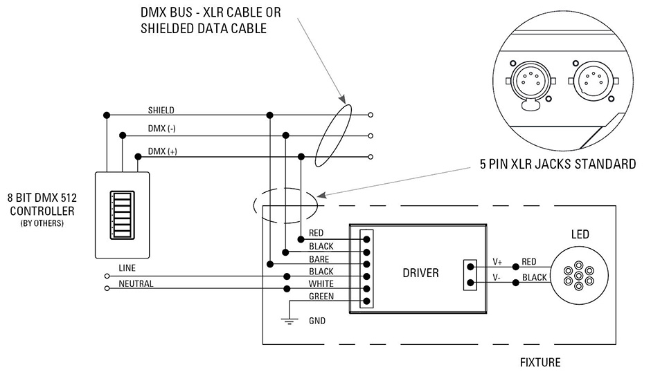
5 pin dmx wiring diagram albertasafety org. Easy dmx512 decoder feature standard dmx512 compliant control interface, enable to set the dmx address freely. Here�s a summary of best practices we recommend for how to wire dmx lighting systems: Configuring your driver over dmx in download the software from your driver’s product web page and connect a usb tongle to dmx in to configure your driver. 19″ controller and edn direct.
 Source: ledlightinghut.com
Data + (pair 1 true) 3. Sympl dmx node e:net connection dmx/e:pix connection to other dmx nodes dmx/e:pix connection pin 3: Easy dmx512 decoder feature standard dmx512 compliant control interface, enable to set the dmx address freely. New to lighting and need to understand dmx wiring? Please check for the latest updates and changes on the traxon website.
 Source: the-sun-that-never-sets.blogspot.com
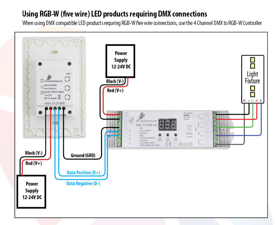
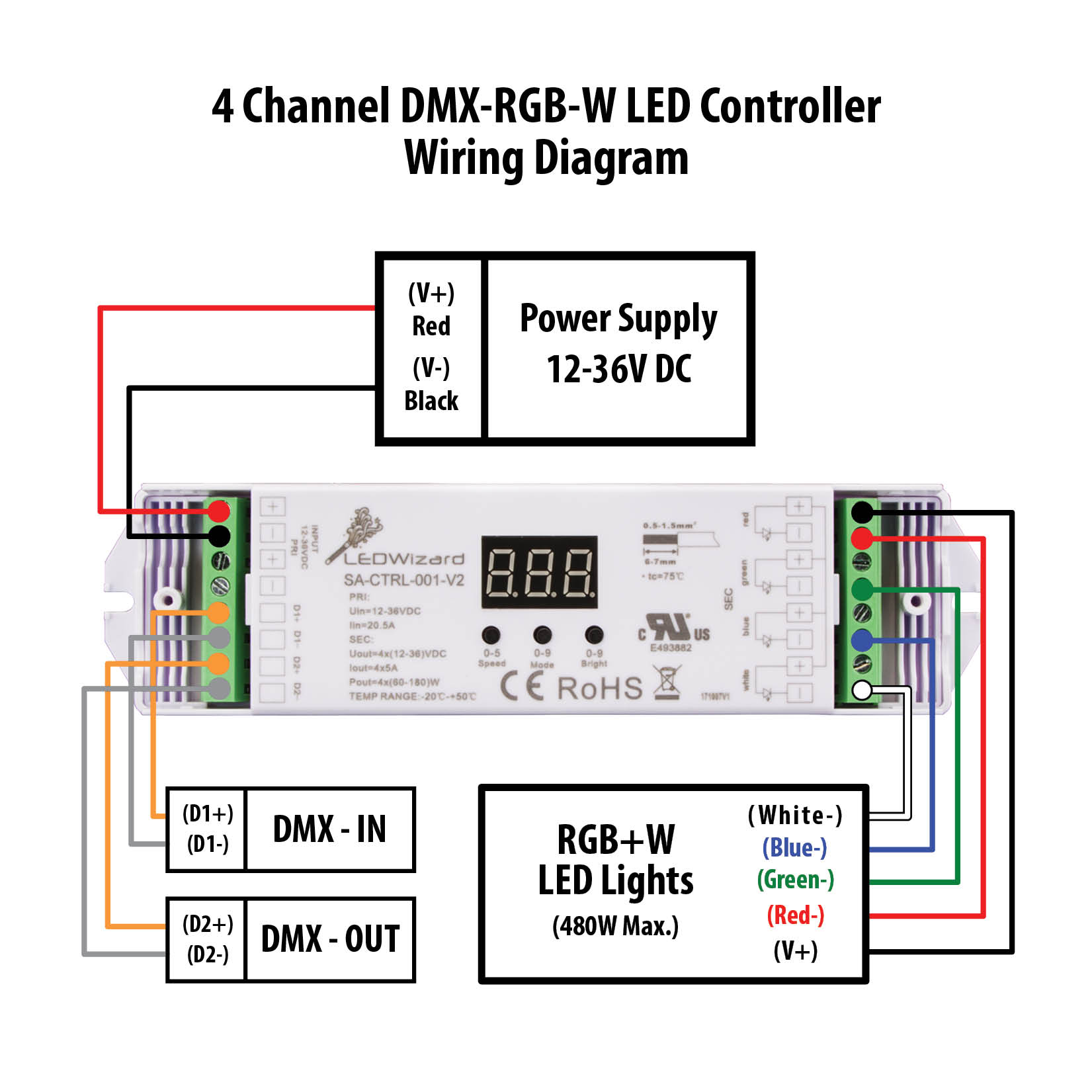
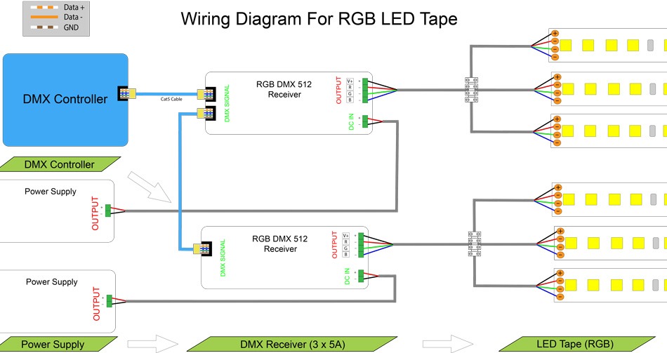
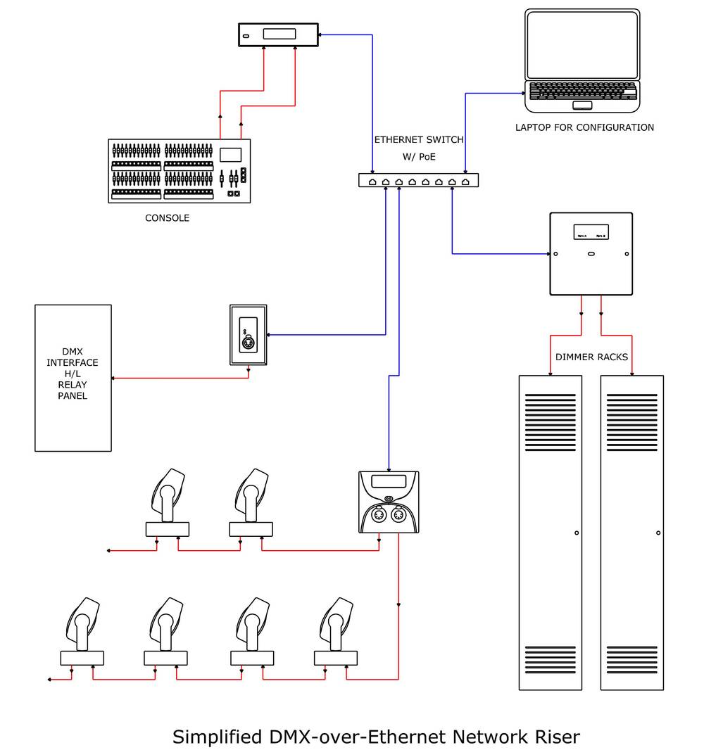
Wiring diagram and schematic role. The daisy chain is a simple wiring method where you wire each fixture looping out of the previous fixture to create a line of fixtures connected back to the console. Wiring diagram for dmx controllers led lighting tutorials control installation pharos controls kim layout what you need to know when working with b h explora dimming solutions usai slc controller cv 4x5a 12 36v rgbw din the light group 24ch rgb decoder 3ch 650ma driver in out ppt graphic representation jesco. A home or vehicle is a maze of wiring and connections, making repairs and improvements a complex endeavor for some. March 30, 2018 1 0.
 Source: 17.csu-lichtenhof.de
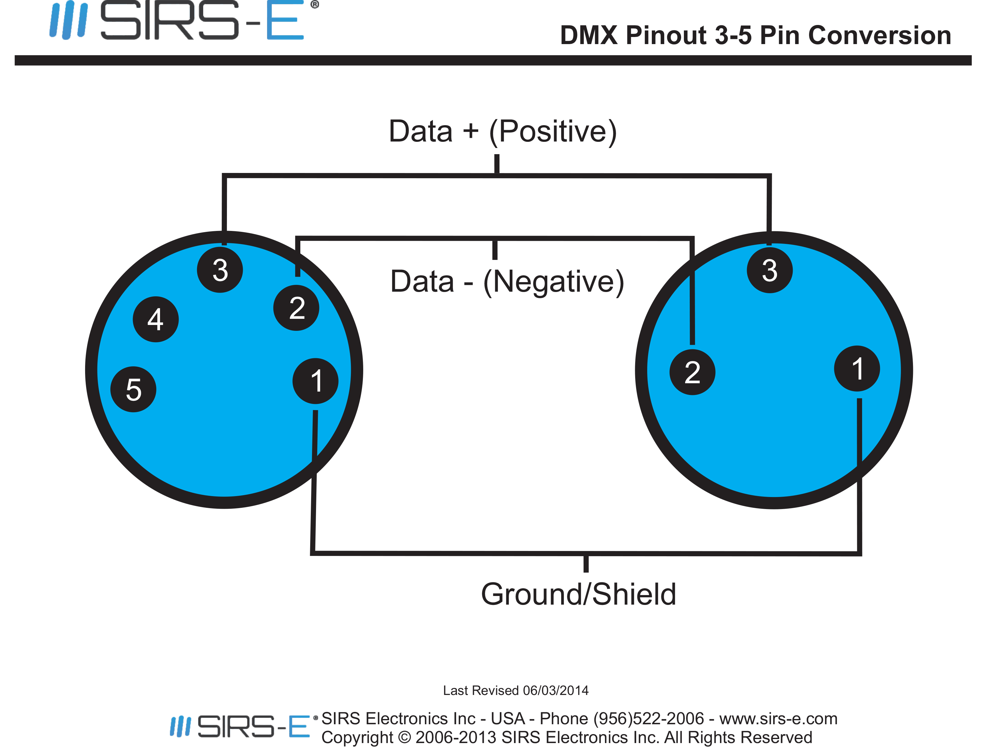
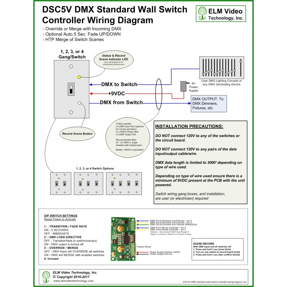
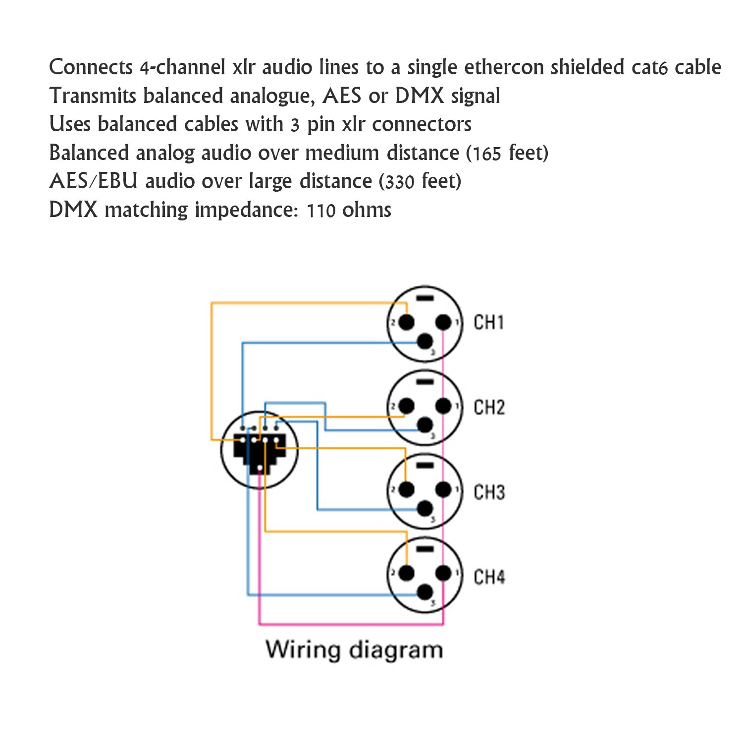
However some older units still use the 5 pin connectors with only three pins used. The trouble in fact is that all car is different. 19″ controller and edn only. Configuring your driver over dmx in download the software from your driver’s product web page and connect a usb tongle to dmx in to configure your driver. A common wiring scheme is studiohub which allows two 3 pin xlr connectors per rj45 connector this scheme can be adapted for dmx too.
 Source: solidapollo.com
19″ controller and edn via switchs. Dmx is a protocol founded in the theatre lighting industry and is often specified when a large amount of colour changing fittings need to be controlled simultaneously. And show address via digital numueric display. 3 channels per dot dmx/rdm: A dmx output sends out a signal to communicate with lighting fixtures.
 Source: sirs-e.com
• each terminal accepts up to two 18 awg (1.0 mm2) wires. Constant current dmx decoder px707 4 channels 200 1600ma per channel the current of each channel can be set separately dmx led controller constant current. Dmx extension cable 5pin xlr slate plp155 adapter 5 pin male blizzard 25q 25 hybrid bsp805m to turnaround kamby dk test about pinout 3 7 appendix e dmx512 connector and uhf transmitter input jack wiring female 512 adaptor 6. 4 channels per dot rgb: Connect dmx decoder similar the wiring diagram 2.
 Source: wiringschemas.blogspot.com
Dmx (digital multiplex) is a communications protocol used mainly to control stage lighting. A dmx output sends out a signal to communicate with lighting fixtures. Dmx to rj45 wiring diagram dmx discover your wiring diagram dmx diagram rj45. Pinout standards for dmx and cat5; Use twisted pair cables with an impedance of 120ω and a low capacitance.
 Source: solidapollo.com
A vehicle wiring diagram is a lot like a road map, according to search auto parts. These diagrams are not intended to specify all equipment necessary for a given dimming circuit. 19″ controller and edn via a flat network. Here�s a summary of best practices we recommend for how to wire dmx lighting systems: However some older units still use the 5 pin connectors with only three pins used.
 Source: instyleled.co.uk
A common wiring scheme is studiohub which allows two 3 pin xlr connectors per rj45 connector this scheme can be adapted for dmx too. Constant current dmx decoder px707 4 channels 200 1600ma per channel the current of each channel can be set separately dmx led controller constant current. 19″ controller and edn via a flat network. Electrical wiring diagrams for light switches electrical wiring diagrams for lighting electrical wiring diagrams for multiple lights. Utp cat5 or cat6 network cable is another option but it has a slightly lower impedance of 100ω
Source: wiringschemas.blogspot.com
Utp cat5 or cat6 network cable is another option but it has a slightly lower impedance of 100ω Constant current dmx decoder px707 4 channels 200 1600ma per channel the current of each channel can be set separately dmx led controller constant current. Wiring diagram for dmx controllers led lighting tutorials control installation pharos controls kim layout what you need to know when working with b h explora dimming solutions usai slc controller cv 4x5a 12 36v rgbw din the light group 24ch rgb decoder 3ch 650ma driver in out ppt graphic representation jesco. The dmx specification allows for two completely separate data channels over the one 5 pin connector, but often you’ll find the cable manufacturers cheap out and only provide a single channel. Dmx (digital multiplex) is a communications protocol used mainly to control stage lighting.
 Source: wiringschemas.blogspot.com
19″ controller and edn only. Pinout standards for dmx and cat5. The dmx specification allows for two completely separate data channels over the one 5 pin connector, but often you’ll find the cable manufacturers cheap out and only provide a single channel. Let’s say you have 4 led fixtures. 5 pin dmx wiring diagram.
 Source: usbwiringdiagram.com
19″ controller and edn via switchs. The dmx data itself requires only 2 of the cable cores plus the shield so recent devices have moved to the 3 pin format. Make a dmx tester dmx dmx lighting tester. Taking into consideration trying to remove, replace or repair the wiring in an automobile, having an accurate and detailed dmx lighting wiring. 19″ controller and edn via switchs.
 Source: fjelloghjem.blogspot.com
• each terminal accepts up to two 18 awg (1.0 mm2) wires. The dmx data itself requires only 2 of the cable cores plus the shield so recent devices have moved to the 3 pin format. Here�s a summary of best practices we recommend for how to wire dmx lighting systems: Most fixtures will have a dmx input and a dmx output. Wiring diagram for dmx controllers led lighting tutorials control installation pharos controls kim layout what you need to know when working with b h explora dimming solutions usai slc controller cv 4x5a 12 36v rgbw din the light group 24ch rgb decoder 3ch 650ma driver in out ppt graphic representation jesco.
 Source: 17.csu-lichtenhof.de
Sympl dmx node e:net connection dmx/e:pix connection to other dmx nodes dmx/e:pix connection pin 3: However some older units still use the 5 pin connectors with only three pins used. The dmx specification allows for two completely separate data channels over the one 5 pin connector, but often you’ll find the cable manufacturers cheap out and only provide a single channel. Connect dmx decoder similar the wiring diagram 2. 5 pin dmx wiring diagram.
 Source: churchtecharts.org
Here is the dmx pin out: Dmx to rj45 wiring diagram dmx discover your wiring diagram dmx diagram rj45. Please check for the latest updates and changes on the traxon website. Connect dmx decoder similar the wiring diagram 2. The dmx specification allows for two completely separate data channels over the one 5 pin connector, but often you’ll find the cable manufacturers cheap out and only provide a single channel.
 Source: alpakaco.blogspot.com
Wiring instructions dmx dimming page 1 dimming driver wiring schemes: Use twisted pair cables with an impedance of 120ω and a low capacitance. 19″ controller and edn direct. A common wiring scheme is studiohub which allows two 3 pin xlr connectors per rj45 connector this scheme can be adapted for dmx too. Please check for the latest updates and changes on the traxon website.
This site is an open community for users to share their favorite wallpapers on the internet, all images or pictures in this website are for personal wallpaper use only, it is stricly prohibited to use this wallpaper for commercial purposes, if you are the author and find this image is shared without your permission, please kindly raise a DMCA report to Us.
If you find this site value, please support us by sharing this posts to your preference social media accounts like Facebook, Instagram and so on or you can also bookmark this blog page with the title dmx wiring diagram by using Ctrl + D for devices a laptop with a Windows operating system or Command + D for laptops with an Apple operating system. If you use a smartphone, you can also use the drawer menu of the browser you are using. Whether it’s a Windows, Mac, iOS or Android operating system, you will still be able to bookmark this website.

