Your Dim and bright wiring diagram images are available in this site. Dim and bright wiring diagram are a topic that is being searched for and liked by netizens now. You can Download the Dim and bright wiring diagram files here. Download all free vectors.
If you’re searching for dim and bright wiring diagram pictures information related to the dim and bright wiring diagram keyword, you have come to the ideal blog. Our website always gives you hints for refferencing the maximum quality video and picture content, please kindly surf and locate more informative video articles and graphics that fit your interests.
Dim And Bright Wiring Diagram. The dimmer 2 will be activated always at previously set brightness level. Din rail mounting enables modular installation alongside crestron® din rail lighting and automation control modules and other third party din rail mountable devices. Rear window defogger page a 1 2. The main fuse and relay panels on most european cars can be found under the hood.
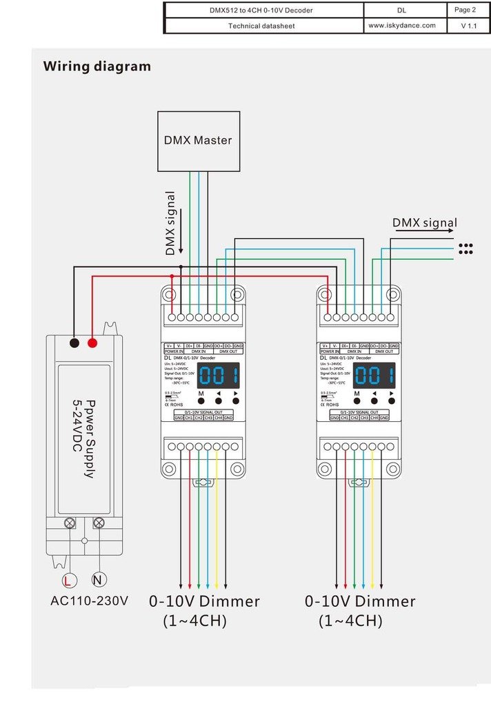 Osram Ot Dim 110v Dimmer Wiring Diagram From schematron.org
5 way trailer wiring diagram allows basic hookup of the trailer and allows using 3 main lighting functions and 1 extra function that depends on the vehicle. When lights are off you can change the light level that the Daytime running lights wiring diagram. Each one of those ideas are illustrated with sensible illustrations. A wiring diagram usually gives opinion practically the relative direction and conformity of. The dimmer 2 will be activated always at previously set brightness level.
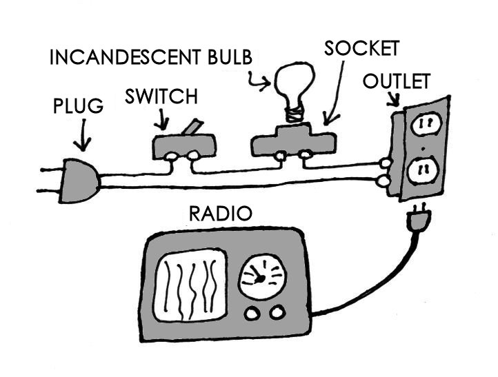
It shows the components of the circuit as simplified shapes, and the capability and signal connections amid the devices.
When lights are off you can change the light level that the lights will turn on to using the dim/bright bar. A wiring diagram usually gives opinion practically the relative direction and conformity of. Din rail mounting enables modular installation alongside crestron® din rail lighting and automation control modules and other third party din rail mountable devices. Short press the push dim switch (<0.5s) to control the lamp on or off c. Evokit step dim wiring diagram line 1 s2 line s1 step dim 16aregulations and electrical codes. Electrician circuit drawings and wiring diagrams youth explore trades skills 3 pictorial diagram:
 Source: wiringforums.com
1 the wiring diagram can not be sure the special demand with the colour specification which customers ask for. The numbers correspond to the din terminal designations. A number of products within our range include daytime running lights drls below is a diagram for customers interested in wiring them up via a relay to allow them to turn off when the low beam headlights are turned on. In rc, the middle left one is completely out. The dim filament is used for the parking lamp function, and the bright filament is used for the turn signal function.

Flip the relay over and you’ll find the relay terminals are also numbered. Short press the push dim switch (<0.5s) to control the lamp on or off c. A diagram that represents the elements of a system using abstract, graphic drawings or realistic pictures. The numbers correspond to the din terminal designations. Bright leds are o dim leds are x in descriptive form, all the freezer leds are fine.
 Source: chanish.org
Bright leds are o dim leds are x in descriptive form, all the freezer leds are fine. If you continue to hold, the lights will dim to minimum level and then turn off. I have included the schematic f. Bright leds are o dim leds are x in descriptive form, all the freezer leds are fine. The guide incorporates a lot of sensible tips for different situations that you might come across if you’re dealing with wiring difficulties.
 Source: wiringforums.com
The null/neutral shall be connected to the load. All the other x lights are merely dim. Led dimming driver wiring diagram created date: Evokit step dim wiring diagram line 1 s2 line s1 step dim 16aregulations and electrical codes. 4 way dimmer switch wiring diagram.
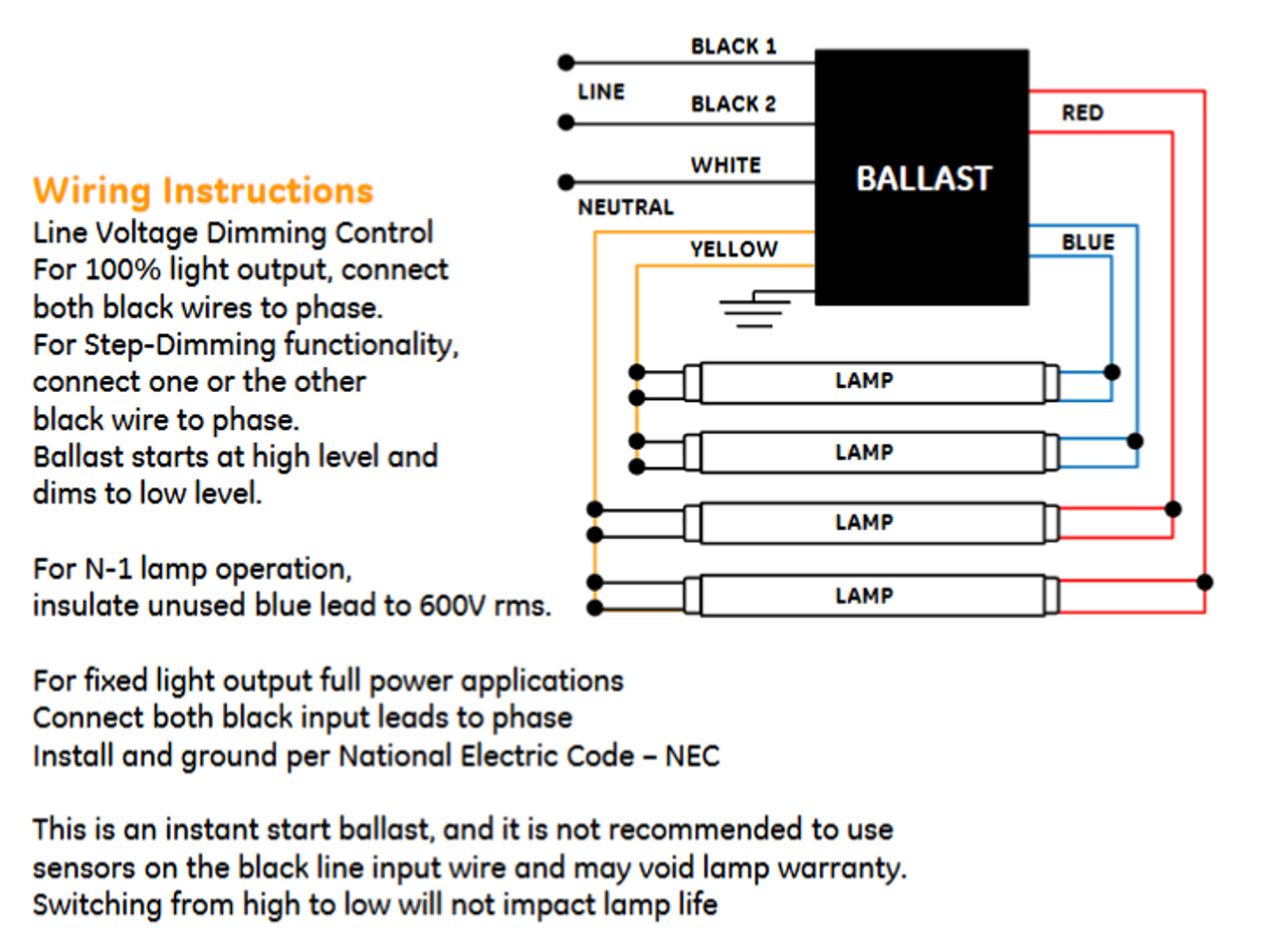 Source: galvinconanstuart.blogspot.com
Connect the wire that continues to load to the dimmer terminal marked (see wiring diagram). The brown wire is what you connect the haz flasher unit to. The purple and grey wires are separate from ac or dc power wiring. Philips evokit led 2x4 and 2x2 the philips evokit is designed for installation in a wide variety of 2x4 and 2x2 indoor fluorescent based fixtures in horizontal applications. It shows the components of the circuit as simplified shapes, and the capability and signal connections amid the devices.
 Source: tonetastic.info
When the load pulls less current than the minimum triac holding If it is disconnected in the wall box, connect with top clamp or other connection. 5 way trailer wiring diagram allows basic hookup of the trailer and allows using 3 main lighting functions and 1 extra function that depends on the vehicle. You would need to run low voltage wiring from the fixture back down to a. Dim/bright bar • seven step blue led display alongside push pad indicates selected light level and reduces brightness when off (nightlight.
 Source: ffcars.com
When lights are off you can change the light level that the Rear window defogger page a 1 2. Any time connecting electrical cabling to an outlet, it may be important to not confuse your wires or push them in the wrong airport terminal. Motorcycle front brake light switch wiring diagram. I have included the schematic f.
 Source: audiokarma.org
Check out our wiring wizard for step by step instructions videos and wiring diagrams including 3 way for installing a dimmer. These replacement modules have wiring diagrams with them. Electrician circuit drawings and wiring diagrams youth explore trades skills 3 pictorial diagram: Watt troffer with 75, life hours. Wiring diagram product size feature •safe and reliable full isolation design •triac dimmable and mosfet dimmable •leading edge dimming and trailing edge dimming both available •great compatibility with a variety of remote controls •innovative minimum brightness setting function •to dim and switch single color dimmable led lamps.

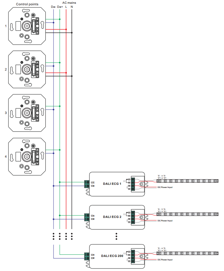
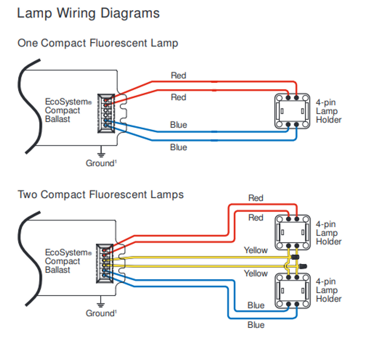
A wiring diagram usually gives opinion practically the relative direction and conformity of. A diagram that uses lines to represent the wires and symbols to represent components. Short press the push dim switch (<0.5s) to control the lamp on or off c. Motorcycle front brake light switch wiring diagram. 1 the wiring diagram can not be sure the special demand with the colour specification which customers ask for.
 Source: atkinsjewelry.blogspot.com
The brown wire is what you connect the haz flasher unit to. The brown wire is what you connect the haz flasher unit to. The dimmer 2 will be activated always at previously set brightness level. 5 way trailer wiring diagram allows basic hookup of the trailer and allows using 3 main lighting functions and 1 extra function that depends on the vehicle. A number of products within our range include daytime running lights drls below is a diagram for customers interested in wiring them up via a relay to allow them to turn off when the low beam headlights are turned on.
 Source: 2020cadillac.com
The numbers correspond to the din terminal designations. The main fuse and relay panels on most european cars can be found under the hood. Led magazine) this is an improvement over triac dimmers that are actually powered by the current flowing through them that is drawn by the led load (see figure 5). The brown wire is what you connect the haz flasher unit to. The dim lights are the top rc led, plus the lowest one on the left, and all three on the right.
 Source: kelvin-okl.blogspot.com
5 way trailer wiring diagram allows basic hookup of the trailer and allows using 3 main lighting functions and 1 extra function that depends on the vehicle. 5 way trailer wiring diagram allows basic hookup of the trailer and allows using 3 main lighting functions and 1 extra function that depends on the vehicle. In rc, the middle left one is completely out. Rear window defogger page a 1 2. Buy cree zrlkv k led troffer.

All the other x lights are merely dim. The main fuse and relay panels on most european cars can be found under the hood. 5 way trailer wiring diagram allows basic hookup of the trailer and allows using 3 main lighting functions and 1 extra function that depends on the vehicle. This is the circuit diagram with the module installed: When lights are off you can change the light level that the
 Source: sunricher.com
5 way trailer wiring diagram allows basic hookup of the trailer and allows using 3 main lighting functions and 1 extra function that depends on the vehicle. The purple and grey wires are separate from ac or dc power wiring. 1 the wiring diagram can not be sure the special demand with the colour specification which customers ask for. Din rail mounting enables modular installation alongside crestron® din rail lighting and automation control modules and other third party din rail mountable devices. Long press the push dim switch (>0.5s) to dim the brightness of light;
 Source: stillwriting-clarissa.blogspot.com
A diagram that represents the elements of a system using abstract, graphic drawings or realistic pictures. Motorcycle front brake light switch wiring diagram. 5 way trailer wiring diagram allows basic hookup of the trailer and allows using 3 main lighting functions and 1 extra function that depends on the vehicle. The dim lights are the top rc led, plus the lowest one on the left, and all three on the right. Here�s the parts diagram for your model:
 Source: pinterest.com
Remove the old touch dimmer control. Wiring diagram product size feature •safe and reliable full isolation design •triac dimmable and mosfet dimmable •leading edge dimming and trailing edge dimming both available •great compatibility with a variety of remote controls •innovative minimum brightness setting function •to dim and switch single color dimmable led lamps. Understanding european din wiring most din relays include a miniature schematic diagram, right on the relay housing. Motorcycle front brake light switch wiring diagram. Bright leds are o dim leds are x in descriptive form, all the freezer leds are fine.
 Source: wiring-pdf.blogspot.com
Wiring diagram product size feature •safe and reliable full isolation design •triac dimmable and mosfet dimmable •leading edge dimming and trailing edge dimming both available •great compatibility with a variety of remote controls •innovative minimum brightness setting function •to dim and switch single color dimmable led lamps. A diagram that represents the elements of a system using abstract, graphic drawings or realistic pictures. This arrangement is provided for easy reference when dealing with a circuit wired in this arrangement. When lights are off you can change the light level that the 365 days to return any part.
 Source: thecj2apage.com
One feeding the dim filament, one feeding the bright filament, and one ground. If it is disconnected in the wall box, connect with top clamp or other connection. In the diagram below a 2 wire nm cable supplies power from the panel to the dimmer box. A diagram that uses lines to represent the wires and symbols to represent components. In rc, the middle left one is completely out.
This site is an open community for users to submit their favorite wallpapers on the internet, all images or pictures in this website are for personal wallpaper use only, it is stricly prohibited to use this wallpaper for commercial purposes, if you are the author and find this image is shared without your permission, please kindly raise a DMCA report to Us.
If you find this site helpful, please support us by sharing this posts to your favorite social media accounts like Facebook, Instagram and so on or you can also save this blog page with the title dim and bright wiring diagram by using Ctrl + D for devices a laptop with a Windows operating system or Command + D for laptops with an Apple operating system. If you use a smartphone, you can also use the drawer menu of the browser you are using. Whether it’s a Windows, Mac, iOS or Android operating system, you will still be able to bookmark this website.


