Your Derale fan wiring diagram images are ready. Derale fan wiring diagram are a topic that is being searched for and liked by netizens today. You can Download the Derale fan wiring diagram files here. Get all free photos.
If you’re searching for derale fan wiring diagram pictures information linked to the derale fan wiring diagram interest, you have pay a visit to the right site. Our website frequently provides you with suggestions for downloading the maximum quality video and image content, please kindly hunt and find more informative video articles and graphics that fit your interests.
Derale Fan Wiring Diagram. Description 2 relay wire harness 2 40/60 amp relay tools needed wire stripper crimping tool important each relay will control up to two different fans with a combined maximum draw of 25 continuous amps. Using a yellow butt connector and the supplied red wire, connect one end of the 10 ga. Derale performance, los angeles, ca 800.421.6288 www.derale.com installation instructions single stage electric fan thermostat part # 16735 (continues on reverse side) kit contents qty. Electric fan relay harness part # 16763 derale performance, los angeles, ca 800.421.6288 www.derale.com.
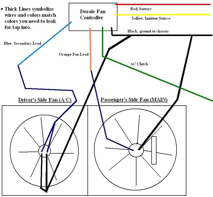 How to hook up a Derale Fan Controller 3000GT/Stealth From 3si.org
Page 4 optional relay overrides temp sensor and turns on fans when a/c is turned on battery 86 30. Positive (+) battery to positive (+) fan lead 14 gauge wire 6 4” wire ties 4 #10 sheet metal screws derale performance, los angeles, ca 800.421.6288 www.derale.com diagram #1 engine puller fan air flow radiator. If you choose to operate the fan using both speeds, two switching devices or a derale dual fan controller part # 16788 or 16789 is recommended. Suggested electric fan wiring diagrams converting a 12 volt switch into a ground switch these diagrams show the use of relays on off sensors on off switches and on off fan controllers. Disregard, cut any exposed copper and tape or shrink wrap the end of the wire.
To quickly test the override circuit, disconnect the green wire and run a jumper wire directly to the positive (+) terminal on the battery.
The dual fan controller and cut the wire to the appropriate length. If you choose to operate the fan using both speeds, two switching devices or a derale dual fan controller part # 16788 / 16789 must be used. Below is the wiring schematic diagram for connecting a spst toggle switch. The dual fan controller and cut the wire to the appropriate length. If you choose to operate the fan using both speeds, two switching devices or a derale dual fan controller part # 16788 or 16789 is recommended. Electric fan relay harness part # 16763 derale performance, los angeles, ca 800.421.6288 www.derale.com.

Loose wire to the vehicles positive (+) terminal on the battery. Page 4 optional relay overrides temp sensor and turns on fans when a/c is turned on battery 86 30. The derale control module is designed to adjust the electric fan speedpwm to maintain the optimal engine temperature. Using a yellow butt connector and the supplied red wire, connect one end of the 10 ga. (see diagram #4 on reverse side) red wire (harness side):
 Source: wiringdiagramall.blogspot.com
If fan started, reattach the green wire to the proper (+) wire on the a/c clutch or manual switch. Connect one end of the 10 ga. The adjustable temp controller, has two wires connected to it both go to separate grounds, and of course the sensor in the rad. Suggested electric fan wiring diagrams converting a 12 volt switch into a ground switch these diagrams show the use of relays on off sensors on off switches and on off fan controllers. Diagram #4 diagram #2 diagram #3 for manual switch wiring.
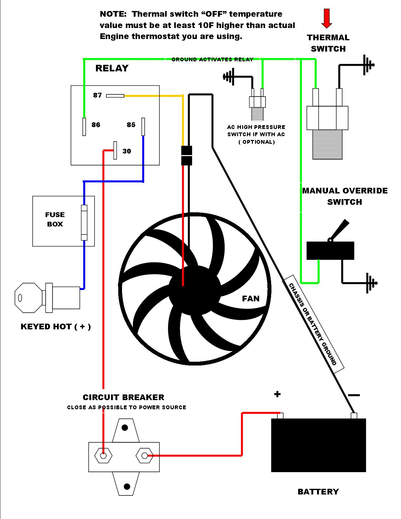 Source: 2020cadillac.com
Using the blue butt connector provided, attach the other end of the loose red wire to the positive (+) lead on the electric fan. Suggested electric fan wiring diagrams converting a 12 volt switch into a ground switch these diagrams show the use of relays on off sensors on off switches and on off fan controllers. Fans, the total continuous amperage cannot exceed 25 amps. Radiator fan switch wiring diagram. To positive (+) 12v battery.
 Source: ls1tech.com
If fan started, reattach the green wire to the proper (+) wire on the a/c clutch or manual switch. 2 to 1 and 3. Here is a listing of the parts you will need: There is a jumper from 86 to 30. Positive (+) battery to positive (+) fan lead

(see diagram #3 on reverse side). The dual fan controller and cut the wire to the appropriate length. Now take the power wire from your fan and connect it to the wire that is going through the firewall. Derale performance, los angeles, ca 800.421.6288 www.derale.com thermostat probe installation 1. To quickly test the override circuit, disconnect the green wire and run a jumper wire directly to the positive (+) terminal on the battery.
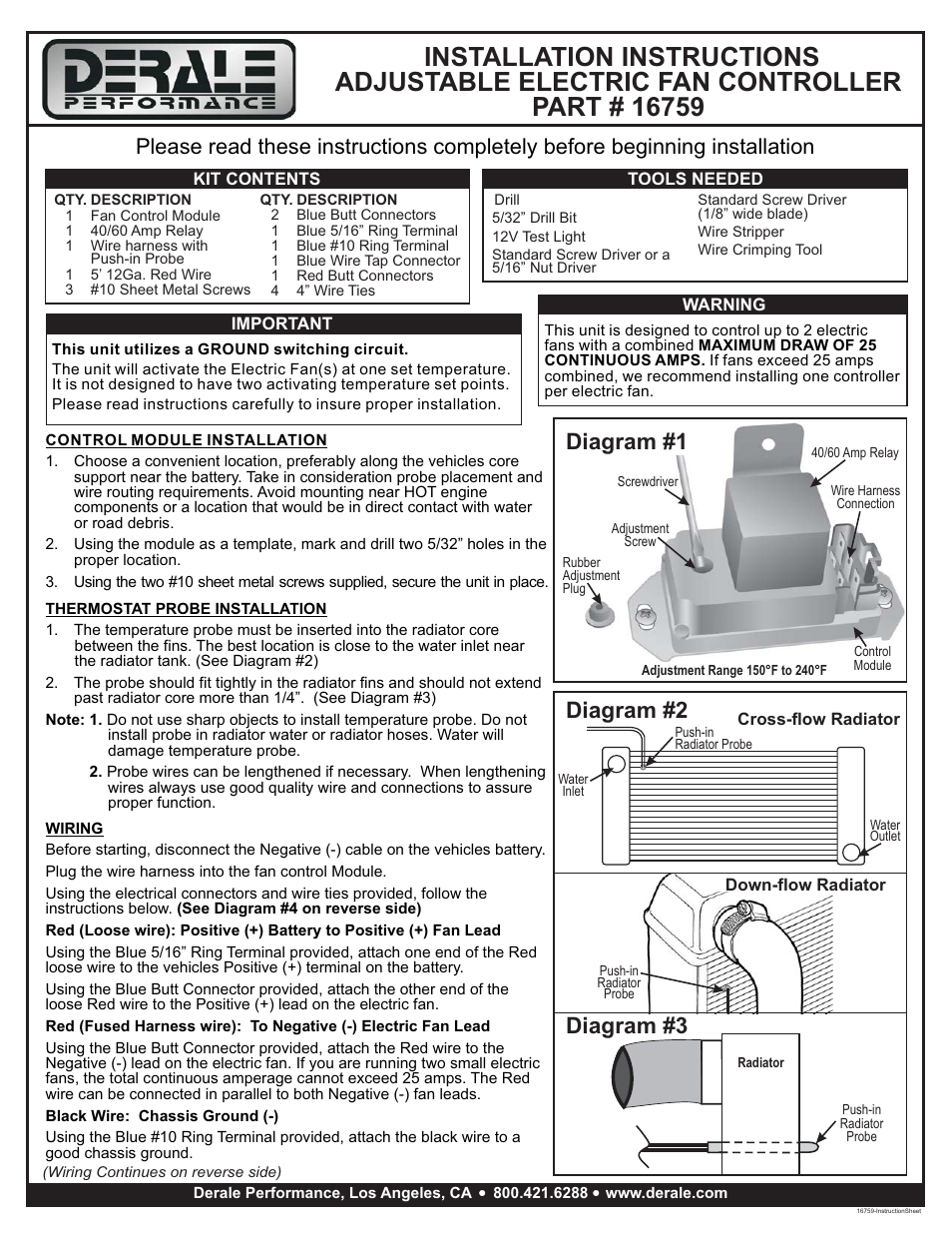 Source: lapakpromo-burhanrengas.blogspot.com
Now take the power wire from your fan and connect it to the wire that is going through the firewall. Dual fan wiring diagram connector to spal fan 12 gauge wire 10 gauge wire relay detail: , using a blue butt connector provided attach the orange wire to the positive (+) electric fan lead. Disregard, cut any exposed copper and tape or shrink wrap the end of the wire. Installation instructions high output 2 speed rad fan.
 Source: rafiqahumuhabibah.blogspot.com
The derale high amperage adjustable dual fan controller is designed to. 14 gauge wire 6 4” wire ties 4 #10 sheet metal screws derale performance, los angeles, ca 800.421.6288 www.derale.com diagram #1 engine puller fan air flow radiator. That controller turns both fans on at the same time, the high starting load and voltage drop that goes with it kills the built in derale relay and blows the 30amp fuse when the under hood heat goes up. If you dont have the same setup as the op just add a relay for the fan circuit, prefferably a 40 amp bosch, and use the derale controller relay to activate the bosch relay coil, that way the derale control will last as it is only handling a small amount of current. How to install a fan controller my pro street.
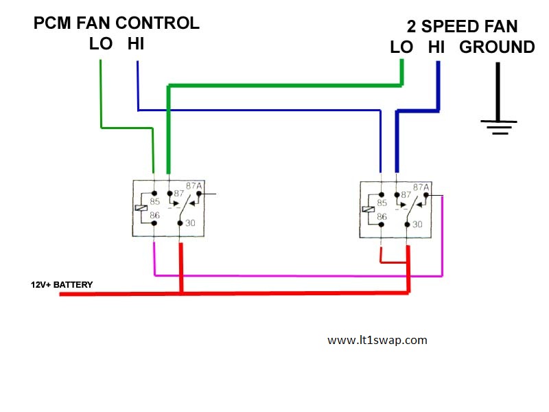 Source: ls1tech.com
The adjustable temp controller, has two wires connected to it both go to separate grounds, and of course the sensor in the rad. Description 2 relay wire harness 2 40/60 amp relay tools needed wire stripper crimping tool important each relay will control up to two different fans with a combined maximum draw of 25 continuous amps. Now take the power wire from your fan and connect it to the wire that is going through the firewall. Using the electrical connectors and wire ties provided, follow the instructions below. Installation instructions high output 2 speed rad fan.
 Source: hotrod.com
Dual fan wiring diagram connector to spal fan 12 gauge wire 10 gauge wire relay detail: Radiator probe outlet qty description. Connect one end of the 10 ga. Red wire to the fan #2 (remaining fan) positive (+) wire. Description 2 relay wire harness 2 40/60 amp relay tools needed wire stripper crimping tool important each relay will control up to two different fans with a combined maximum draw of 25 continuous amps.
 Source: 3si.org
Derale performance, los angeles, ca 800.421.6288 www.derale.com thermostat probe installation 1. Red wire to the fan #2 (remaining fan) positive (+) wire. Derale adjustable fan switch (part #16759) spst 30 amp relay that is normally closed. To positive (+) 12v battery. There is a jumper from 86 to 30.
 Source: hotrod.com
(see diagram #3 on reverse side). Below is the wiring schematic diagram for connecting a spst toggle switch. Installation instructions high output 2 speed rad fan. To fan 2 positive electric fan lead 1. To quickly test the override circuit, disconnect the green wire and run a jumper wire directly to the positive (+) terminal on the battery.

To positive (+) 12v battery. Red wire connected to the fan #2 positive lead to the red wire (furthest. Derale fan controller wiring diagram. The hot goes to fuse, and then to 86 on relay. The derale high amperage adjustable dual fan controller is designed to.
 Source: flickr.com
(see diagram #3 on reverse side) red (loose wire): If you choose to operate the fan using both speeds, two switching devices or a derale dual fan controller part # 16788 or 16789 is recommended. If you dont have the same setup as the op just add a relay for the fan circuit, prefferably a 40 amp bosch, and use the derale controller relay to activate the bosch relay coil, that way the derale control will last as it is only handling a small amount of current. The two wires from the fan run directly to 85 and 87 on the relay. Connect one end of the 10 ga.

The derale high amperage adjustable dual fan controller is designed to operate two electric fans at different activating temperatures. Below is the wiring schematic diagram for connecting a spst toggle switch. 2 speed electric cooling fan wiring diagram youtube. Now take the power wire from your fan and connect it to the wire that is going through the firewall. The adjustable temp controller, has two wires connected to it both go to separate grounds, and of course the sensor in the rad.
 Source: manualsdir.com
If you wire the derale ground circuit to the oe relay coil ground as i described, it will prolong the life of the controller. Diagram #4 derale perfpormance sensor override y sensor n y ion r er n s s ( ) a c u.s. 2 to 1 and 3. Derale adjustable fan switch (part #16759) spst 30 amp relay that is normally closed. Derale performance, los angeles, ca 323.266.3850 www.derale.com diagram #1 engine puller fan air flow radiator diagram #2.
 Source: hotrod.com
To fan 2 positive electric fan lead 1. Derale adjustable fan switch (part #16759) spst 30 amp relay that is normally closed. Page 4 optional relay overrides temp sensor and turns on fans when a/c is turned on battery 86 30. The hot goes to fuse, and then to 86 on relay. The derale high amperage adjustable dual fan controller is designed to operate two electric fans at different activating temperatures.
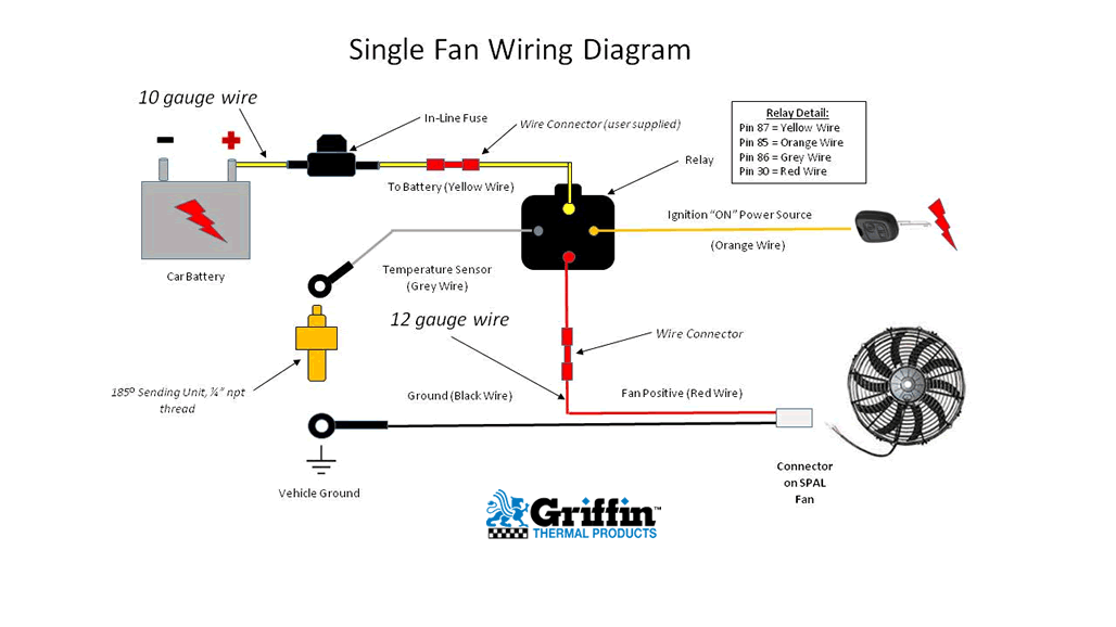 Source: wiringdiagram.2bitboer.com
If fan started, reattach the green wire to the proper (+) wire on the a/c clutch or manual switch. If you choose to operate the fan using both speeds, two switching devices or a derale dual fan controller part # 16788 or 16789 is recommended. Fans, the total continuous amperage cannot exceed 25 amps. If fan started, reattach the green wire to the proper (+) wire on the a/c clutch or manual switch. (see diagram #4 on reverse side) red (loose wire):
 Source: pinterest.com
(see diagram #3 on reverse side). Below is the wiring schematic diagram for connecting a spst toggle switch. Now take the power wire from your fan and connect it to the wire that is going through the firewall. If you dont have the same setup as the op just add a relay for the fan circuit, prefferably a 40 amp bosch, and use the derale controller relay to activate the bosch relay coil, that way the derale control will last as it is only handling a small amount of current. Red wire connected to the fan #2 positive lead to the red wire (furthest.
This site is an open community for users to do submittion their favorite wallpapers on the internet, all images or pictures in this website are for personal wallpaper use only, it is stricly prohibited to use this wallpaper for commercial purposes, if you are the author and find this image is shared without your permission, please kindly raise a DMCA report to Us.
If you find this site convienient, please support us by sharing this posts to your favorite social media accounts like Facebook, Instagram and so on or you can also save this blog page with the title derale fan wiring diagram by using Ctrl + D for devices a laptop with a Windows operating system or Command + D for laptops with an Apple operating system. If you use a smartphone, you can also use the drawer menu of the browser you are using. Whether it’s a Windows, Mac, iOS or Android operating system, you will still be able to bookmark this website.
