Your Derale fan controller wiring diagram images are available in this site. Derale fan controller wiring diagram are a topic that is being searched for and liked by netizens now. You can Download the Derale fan controller wiring diagram files here. Get all royalty-free vectors.
If you’re looking for derale fan controller wiring diagram pictures information related to the derale fan controller wiring diagram interest, you have visit the ideal blog. Our website always provides you with hints for seeing the highest quality video and picture content, please kindly search and locate more informative video articles and graphics that fit your interests.
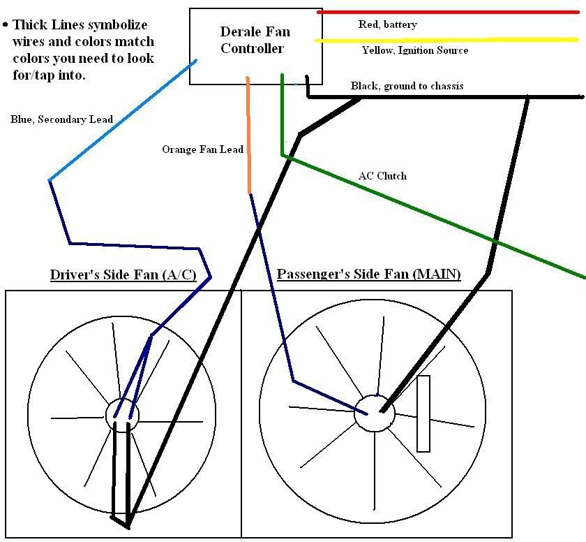
Derale Fan Controller Wiring Diagram. This should turn the fan(s) on immediately. They switched the unit from being a positive switching circuit to a negative switching circuit. Reference diagrams #7&8onpage 2 the electric fan assembly is built using a high output two speed motor. Breaker to the red wire (harness side) located on the dual fan controller and cut the wire to the appropriate length.
 The Derale Fan Controller Can Save Your Electrical Wiring From hotrod.com
In the event of an electrical short, the breaker will “trip” and open the connection between the battery and the. How to wire dual electric cooling fans properly fan relay kit instructions automotive gtsparkplugs faq 3 wiring question spal help honda tech hyundai diagram radiator location audiworld 2004 focus resistor problem no low sd a add mgb recreating an. 02 wrx fog light wiring diagram; Recently, derale redesigned one of their adjustable electrical fan controllers. Switch and outlet wiring diagram; Take the supplied rubber fan shroud seal and install it onto the bottom edge of the fan shroud assembly.
Reference diagrams #7 & 8 on page 3 the electric fan assembly is built using a high output two speed motor.
06 subaru legacy gt wiring diagram; Breaker to the red wire (harness side) located on the dual fan controller and cut the wire to the appropriate length. Pioneer avh x7700bt wiring diagram; Switch and outlet wiring diagram; 02 wrx fog light wiring diagram; Dodge viper, ford taurus, or lincoln mark viii.
 Source: hotrod.com
These fans exceed the amperage & functionality capabilities of this fan controller. Replacement for rbm style 91 relays of the same specifications. Cut off any excess rubber. Derale performance, los angeles, ca 800.421.6288 www.derale.com. They switched the unit from being a positive switching circuit to a negative switching circuit.
 Source: etrailer.com
Diagram #1 this unit utilizes an auto resetting circuit breaker to protect the fans and controller circuit. Pioneer avh x7700bt wiring diagram; Reference diagrams #7&8onpage 2 the electric fan assembly is built using a high output two speed motor. Route the red 10 wire now connected to the auxiliary side of the circuit breaker to the positive (+) battery. 15 pin vga to mini usb wiring diagram;
 Source: hotrod.com
Connect wire using the supplied yellow butt connector. 06 subaru legacy gt wiring diagram; Using a yellow butt connector and the supplied 10 ga. As far as the fan controller is concerned, i had the derale pwm (part number 16795) controller for a while, but i didn�t like that it didn�t provide for a simple override on/off switch. Dodge viper, ford taurus, or lincoln mark viii.

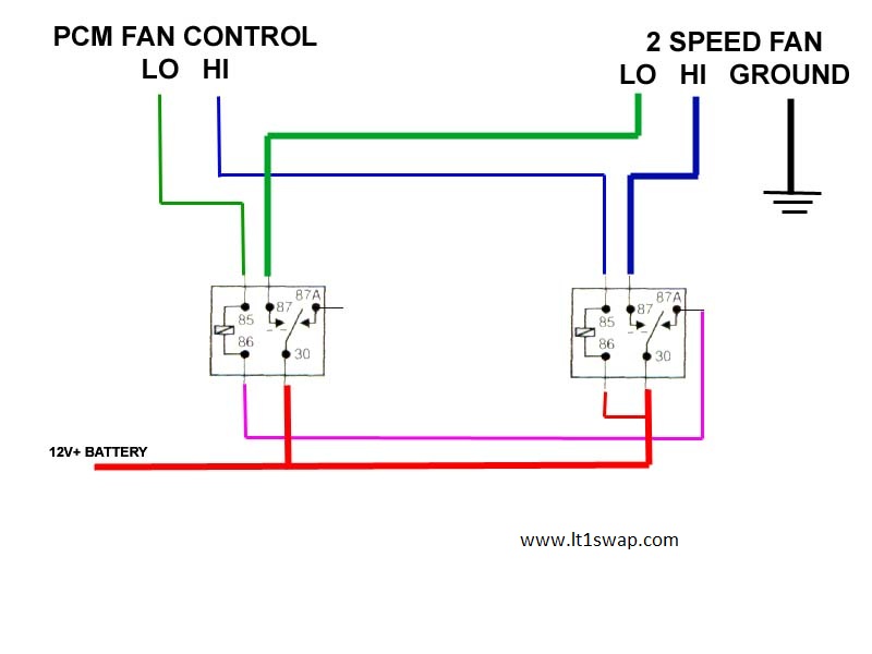
Using the first diagram for the gm part of the circuit, eliminate the old derale part of the diagram and using the red (counterintuitive) wire from the derale relay of the new diagram, splice it to the ground side of the cooling fan relay coil.like i said which ever one grounds the circuit , runs the fan. Diagram #1 this unit utilizes an auto resetting circuit breaker to protect the fans and controller circuit. Description 2 blue butt connectors 02 ford ranger test ignition wiring diagram; , using a blue butt connector provided attach the orange wire to the positive (+) electric fan lead.
 Source: rafiqahumuhabibah.blogspot.com
Derale performance, los angeles, ca 800.421.6288 www.derale.com installation 1. 06 subaru legacy gt wiring diagram; They switched the unit from being a positive switching circuit to a negative switching circuit. It can be used as a fan relay, pump relay or blower relay and. In the event of an electrical short, the breaker will “trip” and open the connection between the battery and the.
 Source: guide.alibaba.com
Take the supplied rubber fan shroud seal and install it onto the bottom edge of the fan shroud assembly. Take the supplied rubber fan shroud seal and install it onto the bottom edge of the fan shroud assembly. 06 subaru legacy gt wiring diagram; Radiator fan switch wiring diagram. Using a yellow butt connector and the supplied 10 ga.
 Source: hotrod.com
Factory other source cards linus tech tips diagram cooling mac pro powermac delta pinouts rellimmot project log controller microcontroller based projects with need help why control sd for electronic equipment analog devices macpro pinout using raspberry pi monitor its driftkingtw s. Breaker to the red wire (harness side) located on the dual fan controller and cut the wire to the appropriate length. 02 wrx fog light wiring diagram; Reference diagrams #7&8onpage 2 the electric fan assembly is built using a high output two speed motor. Red wire, connect one end of the red wire to the #1 electric fan positive (+) wire.
 Source: 3si.org
Route the red 10 wire now connected to the auxiliary side of the circuit breaker to the positive (+) battery. Diagram #1 this unit utilizes an auto resetting circuit breaker to protect the fans and controller circuit. As far as the fan controller is concerned, i had the derale pwm (part number 16795) controller for a while, but i didn�t like that it didn�t provide for a simple override on/off switch. Pwm fan wiring diagram wiring diagram line wiring diagram. Help recreating fan wiring diagram using derale controller gm stock system all about circuits.
 Source: ls1tech.com
Derale performance, los angeles, ca 800.421.6288 www.derale.com diagram #2 important wiring important: The best free hvac drawing images from 73 drawings. Derale performance, los angeles, ca 800.421.6288 www.derale.com installation instructions adjustable electric fan controller part # 16749 kit contents qty. Disregard, cut any exposed copper and tape or shrink wrap the end of the wire. This one is a schurz.here�s some similar.

02 wrx fog light wiring diagram; Reference diagrams #7 & 8 on page 3 the electric fan assembly is built using a high output two speed motor. Switch and outlet wiring diagram; The derale high amperage adjustable dual fan controller is designed to operate two electric fans at different activating temperatures. Derale fan controller wiring diagram;
 Source: hotrod.com
If you choose to operate the fan using both speeds two switching devices or a derale dual fan controller part 16788 or 16789 is recommended. That controller turns both fans on at the same time, the high starting load and voltage drop that goes with it kills the built in derale relay and blows the 30amp fuse when the under hood heat goes up. Description 2 blue butt connectors Breaker to the red wire (harness side) located on the dual fan controller and cut the wire to the appropriate length. Derale performance, los angeles, ca 800.421.6288 www.derale.com installation instructions adjustable electric fan controller part # 16749 kit contents qty.
 Source: flickr.com
Cut off any excess rubber. Derale performance, los angeles, ca 800.421.6288 www.derale.com installation instructions adjustable electric fan controller part # 16749 kit contents qty. One of the camaro enthusiasts who is no longer with us, designed a wiring schematic that allowed the gm stock fan controller to work in conjunction with the derale system. See also best way to wash face cloths. This single stage electric fan thermostat will control up to two different fans with acombined maximum draw
 Source: hotrod.com
Mine lasted about 3 stop lights at 96* outside air temp. These fans exceed the amperage & functionality capabilities of this fan controller. Using a table or workbench, lay the electric fan assembly on a flat surface, electric fan facing down. This should turn the fan(s) on immediately. Take the supplied rubber fan shroud seal and install it onto the bottom edge of the fan shroud assembly.
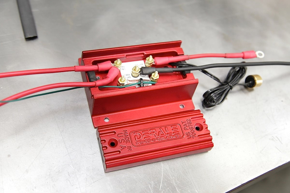 Source: dragzine.com
Diagram #1 this unit utilizes an auto resetting circuit breaker to protect the fans and controller circuit. Help recreating fan wiring diagram using derale controller gm stock system all about circuits. The dual fan controller and cut the wire to the appropriate length. +12v 15amp fuse ignition power. Diagram #4 derale perfpormance sensor override y sensor n y ion r er n s s ( ) a c u.s.

02 ford ranger test ignition wiring diagram; This should turn the fan(s) on immediately. Using a table or workbench, lay the electric fan assembly on a flat surface, electric fan facing down. Derale fan controller wiring diagram; 02 ford ranger test ignition wiring diagram;
 Source: hotrod.com
See also best way to wash face cloths. Also, it was a pain to adjust the cooling points (had to take the cover off, use a small screwdriver, needing an ohm meter). If you choose to operate the fan using both speeds two switching devices or a derale dual fan controller part 16788 or 16789 is recommended. 06 subaru legacy gt wiring diagram; Derale fan controller wiring diagram;
 Source: hotrod.com
Derale fan controller wiring diagram. Red wire, connect one end of the red wire to the #1 electric fan positive (+) wire. One of the camaro enthusiasts who is no longer with us, designed a wiring schematic that allowed the gm stock fan controller to work in conjunction with the derale system. That controller turns both fans on at the same time, the high starting load and voltage drop that goes with it kills the built in derale relay and blows the 30amp fuse when the under hood heat goes up. This one is a schurz.here�s some similar.
 Source: hotrod.com
Derale performance, los angeles, ca 800.421.6288 www.derale.com diagram #2 important wiring important: Diagram #1 this unit utilizes an auto resetting circuit breaker to protect the fans and controller circuit. Now take the power wire from your fan and connect it to the wire that is going through the firewall. Red wire to the fan 2 remaining fan positive wire. Using a yellow butt connector and the supplied 10 ga.
This site is an open community for users to submit their favorite wallpapers on the internet, all images or pictures in this website are for personal wallpaper use only, it is stricly prohibited to use this wallpaper for commercial purposes, if you are the author and find this image is shared without your permission, please kindly raise a DMCA report to Us.
If you find this site serviceableness, please support us by sharing this posts to your favorite social media accounts like Facebook, Instagram and so on or you can also save this blog page with the title derale fan controller wiring diagram by using Ctrl + D for devices a laptop with a Windows operating system or Command + D for laptops with an Apple operating system. If you use a smartphone, you can also use the drawer menu of the browser you are using. Whether it’s a Windows, Mac, iOS or Android operating system, you will still be able to bookmark this website.

