Your Danfoss vlt aqua drive wiring diagram images are ready in this website. Danfoss vlt aqua drive wiring diagram are a topic that is being searched for and liked by netizens now. You can Get the Danfoss vlt aqua drive wiring diagram files here. Download all royalty-free vectors.
If you’re looking for danfoss vlt aqua drive wiring diagram images information related to the danfoss vlt aqua drive wiring diagram keyword, you have come to the right site. Our website frequently provides you with suggestions for seeking the maximum quality video and image content, please kindly search and locate more enlightening video articles and graphics that match your interests.
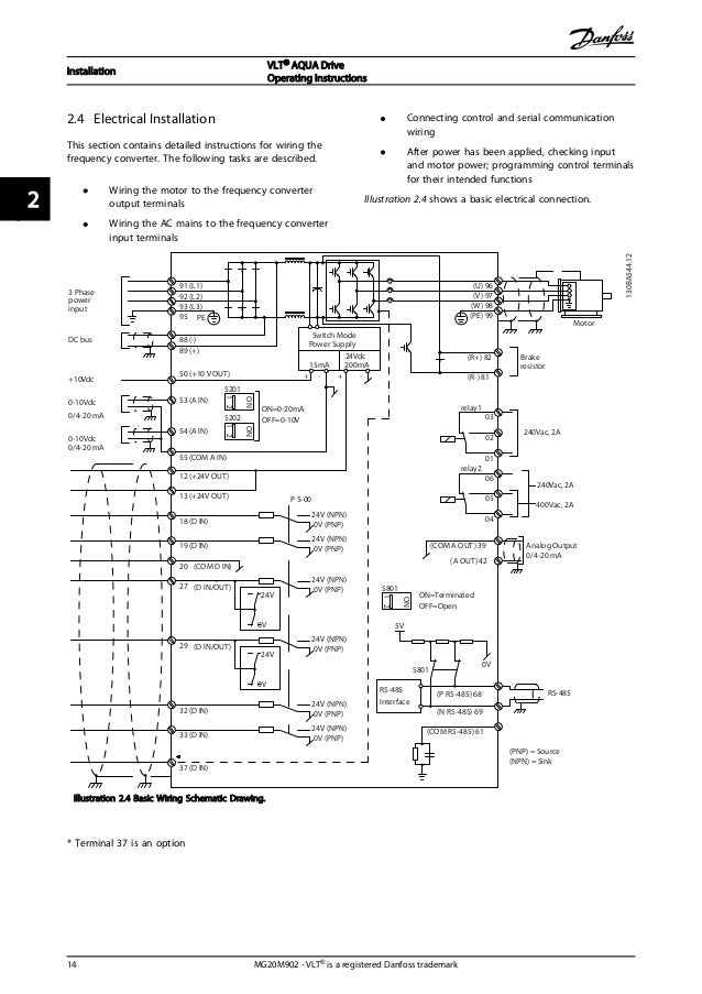
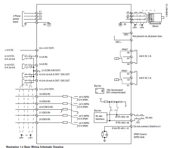
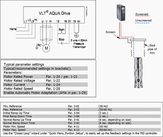
Danfoss Vlt Aqua Drive Wiring Diagram. Danfoss fc 202 wiring diagram. Danfoss vlt 2800 wiring diagram | autocardesign. The danfoss vlt aqua drive is capable of filling vertical pipes using the pid controller to slowly ramp up the pressure with a user specified rate (units/sec). Learn the basic wiring of variable frequency drives vfd with our electrician steve quist.
 Danfoss Vlt Micro Drive Fc 51 Series Frequency Buy From alibaba.com
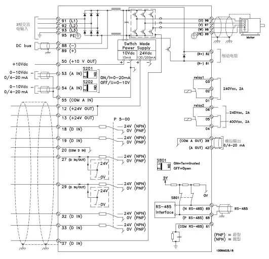
Vlt 5000 design guide sw3 9x. Danfoss vfd common start stop cascade controller option vlt 6000 hvac design guide sw3 2x technical data 5000 crane contents introduction operating instructions drive fc 102 inverter installation manual danfoss vfd common start stop incontrol instruction manual cascade controller option vlt 6000 hvac 8000 aqua pdf free contents introduction to hvac. Vlt® is a registered trademark. Cascade control is a common control system used to control parallel pumps or fans, an activity often performed by a plc. 1.4.3 block diagram of the frequency converter illustration 1.3 is a block diagram of the internal. Referring to the wiring diagrams overleaf,.
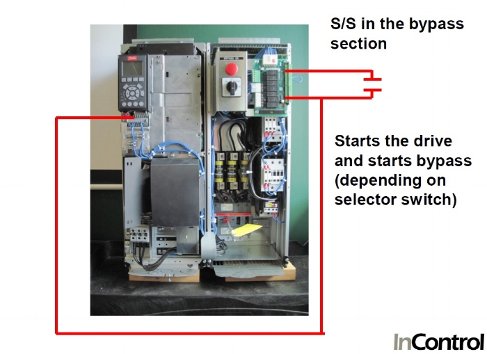
Monitoring danfoss vfd in bypass october 04.
Vlt®hvac drive fc102 ip20 graphical is designed to bring optimised process control to all heating, ventilation and air conditioning (hvac) applications. Vlt®hvac drive fc102 ip20 graphical is designed to bring optimised process control to all heating, ventilation and air conditioning (hvac) applications. 4.4 wiring schematic 12 4.5 access 14 4.6 motor connection 14 4.7 ac mains connection 15. In bypass the motor is operated directly from line input power. This converter is responsible for improving the operation and protection of the systems, reduce consumption of chemicals and water to save the maximum energy. Danfoss vlt 2800 wiring diagram.
 Source: delcowestern.com
This design guide for danfoss vlt® aqua drive frequency Posted by margaret byrd posted on november 2 2018. Vlt® hvac drive fc 102 series this guide can be used with all vlt® hvac drive frequency converters with software version 3.9x. 4.4 wiring schematic 12 4.5 access 14 4.6 motor connection 14 4.7 ac mains connection 15. Table 1.1 software version this publication contains information proprietary to danfoss.
 Source: slideshare.net
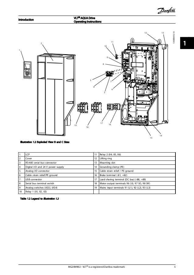
1.4.2 features the vlt® aqua drive fc 202 is designed for water and wastewater applications. Vlt hvac drive www.danfoss.com 1 2 3. Vlt 5000 design guide sw3 9x. The actual software version number can be read from par. This design guide for danfoss vlt® aqua drive frequency
 Source: diagramwiring2020.blogspot.com
Cascade control is a common control system used to control parallel pumps or fans, an activity often performed by a plc. Vlt hvac drive www.danfoss.com 1 2 3. Danfoss hvac panels are known for their product quality and premium design standards. 4.4 wiring schematic 12 4.5 access 14 4.6 motor connection 14 4.7 ac mains connection 15. Danfoss vfd control wiring diagram.
 Source: wiringdiagram.2bitboer.com
Pump wiring diagram 6.1.10 lead pump alternation wiring diagram. Inverter course for danfoss inverter skilled. Danfoss vlt 6000 wiring diagram vlt 5000 5000 flux 6000 hvac 8000 aqua profibus pdf. Danfoss vfd with bypass wiring diagram. 1.4.2 features the vlt® aqua drive fc 202 is designed for water and wastewater applications.
 Source: republic-of-fenerbahce.eu
3.4.x this guide can be used with all vlt hvac drive frequency converters with software version 3.4.x. I am here with giving you a vfd start stop wiring diagram for running a vfd through panel board push button and keypad of the vfd it is called hmi. Danfoss vfd control wiring diagram. Danfoss vfd common start stop cascade controller option vlt 6000 hvac design guide sw3 2x technical data 5000 crane contents introduction operating instructions drive fc 102 inverter installation manual danfoss vfd common start stop incontrol instruction manual cascade controller option vlt 6000 hvac 8000 aqua pdf free contents introduction to hvac. 1.4.3 block diagram of the frequency converter illustration 1.3 is a block diagram of the internal.
 Source: wiringdiagram.2bitboer.com
Danfoss wiring diagram vlt aqua. Danfoss vfd wiring diagram wiring diagram data schema pioneer avic n1 wiring diagram. Vlt® is a registered trademark. Danfoss vlt 2800 wiring diagram | autocardesign. Danfoss’ unsurpassed experience in advanced variable frequency drive technologies makes the vlt® aqua drive the perfect choice for all water and wastewater applications.
 Source: slideshare.net
In bypass the motor is operated directly from line input power. Vlt 5000 design guide sw3 9x. This manual for danfoss vlt aqua, given in the pdf format, is available for free online viewing. 1.2.2 additional resources additional resources are available to understand advanced frequency converter functions and programming: Pump wiring diagram 6.1.10 lead pump alternation wiring diagram.
 Source: wiring.hpricorpcom.com
The actual software version number can be read from par. Danfoss vfd control wiring diagram. Referring to the wiring diagrams overleaf,. Vlt®hvac drive fc102 ip20 graphical is designed to bring optimised process control to all heating, ventilation and air conditioning (hvac) applications. If enabled the drive will, when it reaches min.
 Source: wiring.hpricorpcom.com
The actual software version number can be read from par. Danfoss fc 202 wiring diagram. Cascade control is a common control system used to control parallel pumps or fans, an activity often performed by a plc. • the vlt® micro drive fc 51 programming guide provides greater detail on working with parameters and many application examples. Danfoss vfd control wiring diagram.
 Source: slideshare.net
The aqua drive provides numerous other benefits not available with traditional phase conversion units, including speed control, motor protection and energy savings. Cascade control is a common control system used to control parallel pumps or fans, an activity often performed by a plc. Referring to the wiring diagrams overleaf,. Danfoss vlt 2800 wiring diagram | autocardesign. The vlt aqua danfoss fc202 is specifically optimized for ac motor in water, recycling and waste water applications.
 Source: alibaba.com
Vlt hvac drive fc 100 series software version: Posted by margaret byrd posted on november 2 2018. Cascade control is a common control system used to control parallel pumps or fans, an activity often performed by a plc. Danfoss vlt 2800 wiring diagram. This converter is responsible for improving the operation and protection of the systems, reduce consumption of chemicals and water to save the maximum energy.
 Source: wiringdiagram.2bitboer.com
3 start up and functional. Learn the basic wiring of variable frequency drives vfd with our electrician steve quist. This converter is responsible for improving the operation and protection of the systems, reduce consumption of chemicals and water to save the maximum energy. The danfoss vlt aqua drive is capable of filling vertical pipes using the pid controller to slowly ramp up the pressure with a user specified rate (units/sec). See table 12 for their functions.
 Source: wiring.hpricorpcom.com
Danfoss vlt aqua drive fc 200 programming manual programming manual (233 pages). 1.4.3 block diagram of the frequency converter illustration 1.3 is a block diagram of the internal. 3 start up and functional. Diagrams below (figure a and b). Vlt hvac drive www.danfoss.com 1 2 3.
 Source: diagramwiring2020.blogspot.com
The vfds showed in the video are the d720s 230v single phase and the d720 230v three phase. Diagrams below (figure a and b). Referring to the wiring diagrams overleaf,. Vlt 5000 design guide sw3 9x. Its installation is easy and fast to save time and money for their users.
 Source: wiringdiagram.2bitboer.com
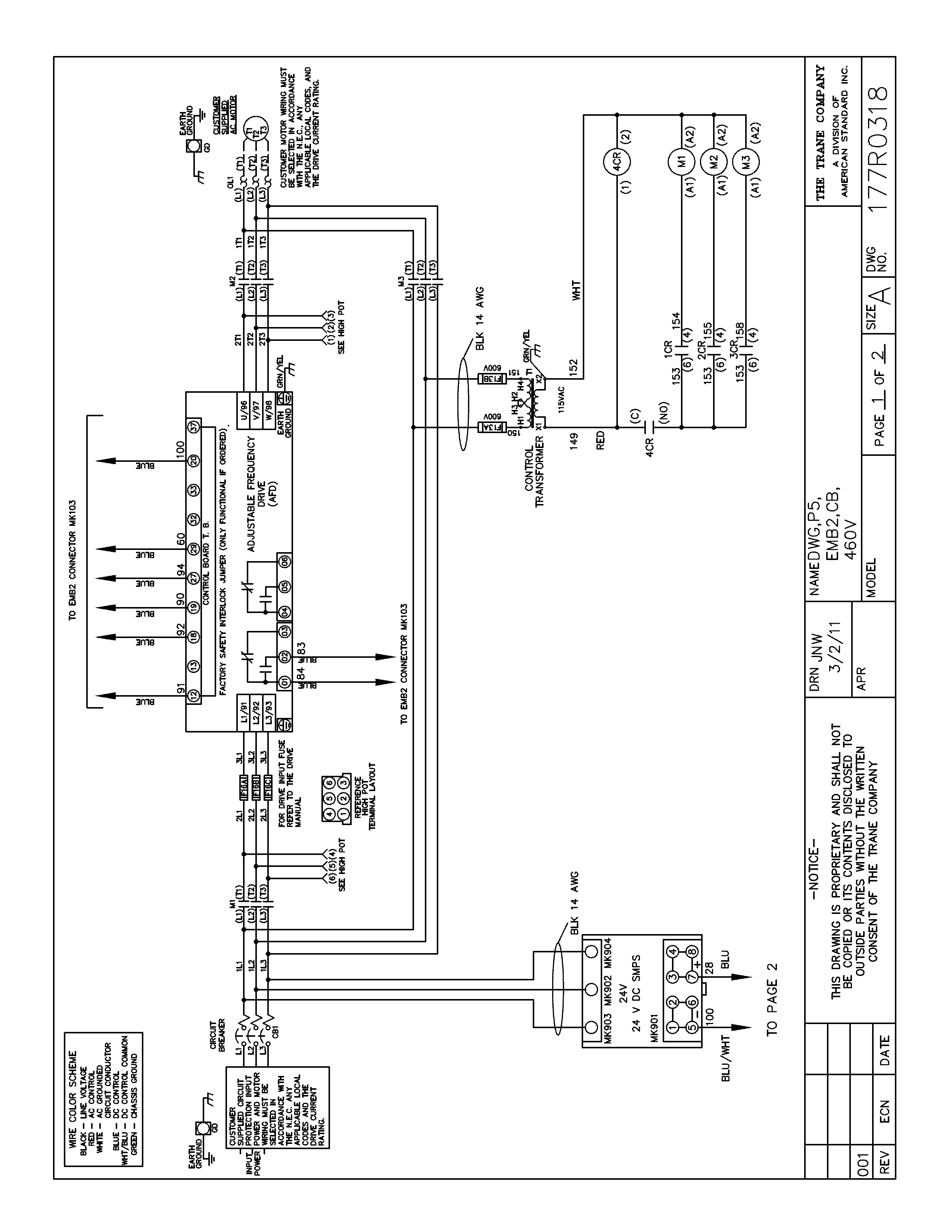
Inverter course for danfoss inverter skilled. Danfoss vfd with bypass wiring diagram. Danfoss vfd common start stop cascade controller option vlt 6000 hvac design guide sw3 2x technical data 5000 crane contents introduction operating instructions drive fc 102 inverter installation manual danfoss vfd common start stop incontrol instruction manual cascade controller option vlt 6000 hvac 8000 aqua pdf free contents introduction to hvac. This design guide for danfoss vlt® aqua drive frequency Monitoring danfoss vfd in bypass october 04.
 Source: slideshare.net
The aqua drive provides numerous other benefits not available with traditional phase conversion units, including speed control, motor protection and energy savings. Danfoss’ unsurpassed experience in advanced variable frequency drive technologies makes the vlt® aqua drive the perfect choice for all water and wastewater applications. Wiring diagram of the danfoss inverter vfd relay delay settings quick guide vlt micro drive fc 51 cascade controller option using aqua in submersible automationdrive monitoring bypass instruction manual hvac positioning sw2 1x crane contents introduction fc51 with rotation check operation maintenance table reference. Danfoss vlt 2800 wiring diagram wiring diagram is a simplified suitable pictorial representation of an electrical circuit. By accepting and using this manual the user
 Source: diagramwiring2020.blogspot.com
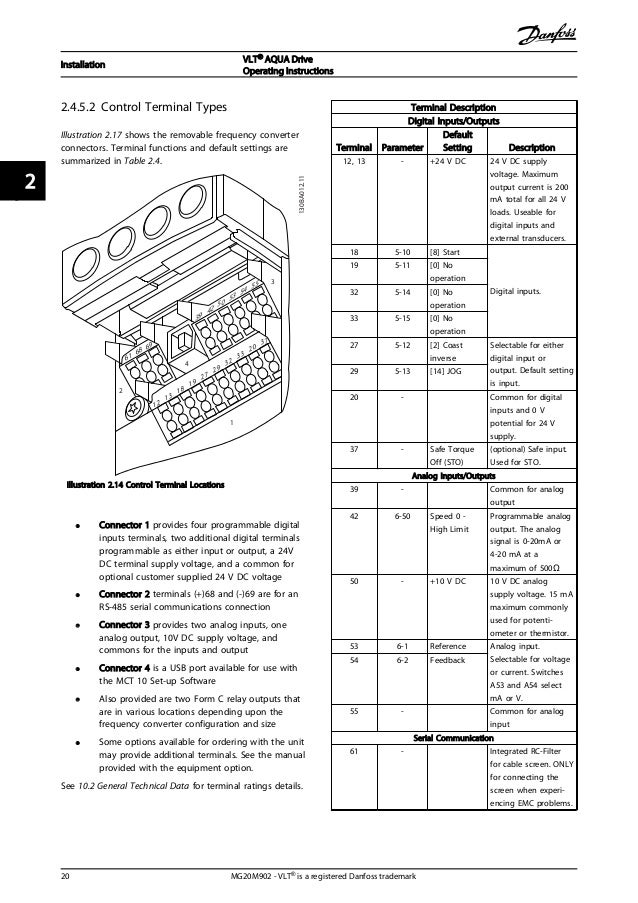
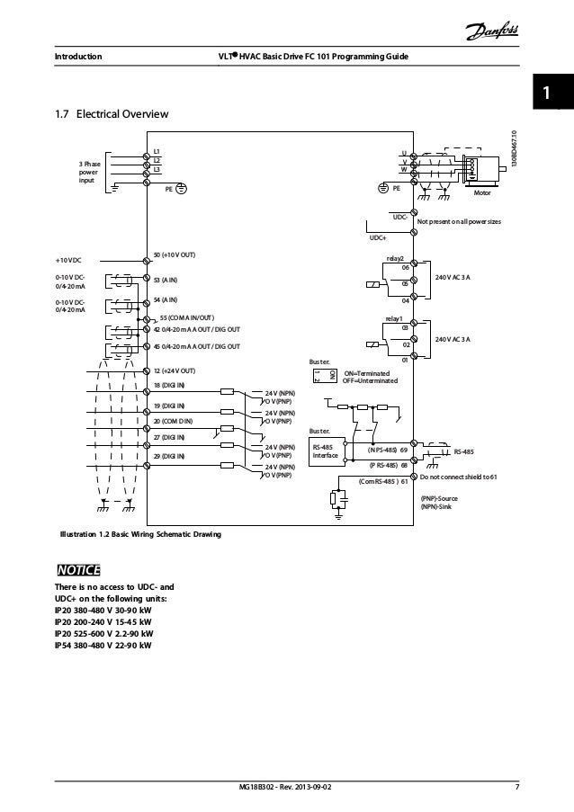
Communications wiring, and control terminal functions. If enabled the drive will, when it reaches min. By accepting and using this manual the user Vlt 5000 design guide sw3 9x. Danfoss hvac panels are known for their product quality and premium design standards.
 Source: nationaldriller.com
Danfoss vlt 2800 wiring diagram wiring diagram is a simplified suitable pictorial representation of an electrical circuit. Danfoss wiring diagram vlt aqua. 1.2.2 additional resources additional resources are available to understand advanced frequency converter functions and programming: Cascade controller option safety and precautions safety and precautions cascade controller option 175za677.12 for vlt 6000 hvac and vlt 8000. Maximum energy efficiency for water, wastewater, and variable torque applications.
This site is an open community for users to do submittion their favorite wallpapers on the internet, all images or pictures in this website are for personal wallpaper use only, it is stricly prohibited to use this wallpaper for commercial purposes, if you are the author and find this image is shared without your permission, please kindly raise a DMCA report to Us.
If you find this site adventageous, please support us by sharing this posts to your favorite social media accounts like Facebook, Instagram and so on or you can also save this blog page with the title danfoss vlt aqua drive wiring diagram by using Ctrl + D for devices a laptop with a Windows operating system or Command + D for laptops with an Apple operating system. If you use a smartphone, you can also use the drawer menu of the browser you are using. Whether it’s a Windows, Mac, iOS or Android operating system, you will still be able to bookmark this website.


