Your Danfoss controller wiring diagram images are available in this site. Danfoss controller wiring diagram are a topic that is being searched for and liked by netizens now. You can Find and Download the Danfoss controller wiring diagram files here. Find and Download all free photos.
If you’re looking for danfoss controller wiring diagram images information linked to the danfoss controller wiring diagram keyword, you have pay a visit to the ideal blog. Our site always provides you with hints for refferencing the maximum quality video and picture content, please kindly surf and locate more informative video articles and graphics that fit your interests.
Danfoss Controller Wiring Diagram. Cascade controller option the voltage of the afd is dangerous whenever the equipment is connected to mains. Controls with low pressure (lp) and high pressure (hp) signal). Global product installation manual pdf manualslib fc 102 hvac drive with bypass rotation check r l deppmann 25 optyma controller and the pump down function user guide ti contactorotor starters types 50 type ci9 motor c19 037h0021 m controls power automation dc ac din rail blog incontrol single phase. In bypass the motor is operated directly from line input power.
 Diagram & Wiring Solution Danfoss Vfd Control Wiring Diagram From diagramwiring2020.blogspot.com
The contact position of which depends on the pressure in the connector and the. W iring & dil switch settings danfoss randall / n. The diagrams below show typical wiring circuit�s with which the wiring conversionsto be used when replacing the following programmers with the fp, cp. Ac dc controller wiring instructions bd compressors pdf o danfoss electronic unit for bd35 50f changing the standard control box on a bd80f wingless bd50f 101n0500 solar picture waecocf 35 repair service of indel b tb 51a compressor sd my ironman icecube 12 volt fridge dulas refrigerator refrigeration parts solution. Washington has page 5/35 4482608 The cut in pressure is 3 5 bar and the cut off pressure is 5 bar.
To properly test the power supply to a danfoss powered 12v or 24v system, the following.
Wiring diagram for tp5000 rt51 and rt52 tp5000 rt51 and rt52 a off b c com on nc no. Wiring diagram and schematic role. Controls danfoss wiring diagram.pdf board recall is a test run for mayoral control having the mayor appoint this many school board members at one time is a backdoor test run for mayoral control over the city’s schools. Controls with low pressure (lp) and high pressure (hp) signal). All 12 volt electrical wiring should be carried out according to the following table: Danfoss fp715si programmer wiring diagram.
 Source: worldvisionsummerfest.com
The cut in pressure is 3 5 bar and the cut off pressure is 5 bar. To ensure correct start and operating conditions, the following cable dimensions must be observed: Danfoss vfd wiring diagram wiring diagram data schema pioneer avic n1 wiring diagram. Controls danfoss wiring diagram.pdf board recall is a test run for mayoral control having the mayor appoint this many school board members at one time is a backdoor test run for mayoral control over the city’s schools. Standard cascade control wiring diagram.
 Source: schematron.org
Wiring diagram for tp5000 rt51 and rt52 tp5000 rt51 and rt52 a off b c com on nc no. Danfoss fp715si programmer wiring diagram. Disconnect wires from ts1 and ts2. See label for current wiring inside cover. The installation guide is intended for use by qualified personnel.
 Source: wiringdiagram.2bitboer.com
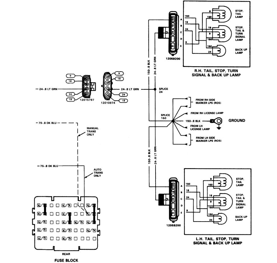
Standard cascade control wiring diagram. See table 12 for their functions. Danfoss pressure switch wiring diagram. To ensure correct start and operating conditions, the following cable dimensions must be observed: Do not interchange ts1 and ts2.
 Source: diynot.com
Cascade controller option the voltage of the afd is dangerous whenever the equipment is connected to mains. Do not interchange ts1 and ts2. Danfoss fp715si programmer wiring diagram. The vfds showed in the video are the d720s 230v single phase and the d720 230v three phase. Danfoss vfd with bypass wiring diagram.
 Source: diagramweb.net
Slave drive in master/slave control wiring diagram. Danfoss randall can accept no responsibility for possible errors in. To ensure correct start and operating conditions, the following cable dimensions must be observed: The contact position of which depends on the pressure in the connector and the. Learn the basic wiring of variable frequency drives vfd with our electrician steve quist.
 Source: wiringall.com
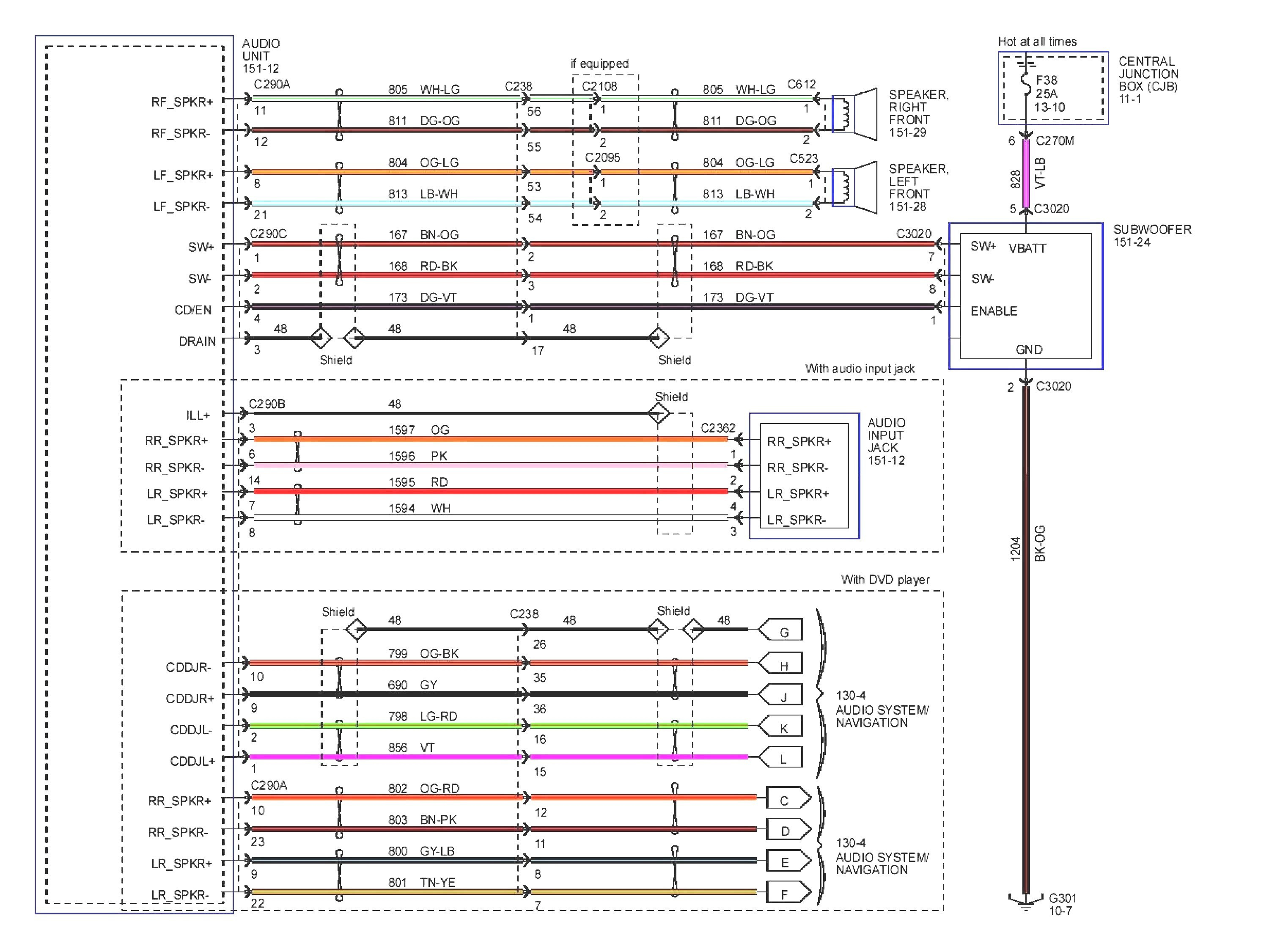
Wiring diagram for tp5000 rt51 and rt52 tp5000 rt51 and rt52 a off b c com on nc no. All 12 volt electrical wiring should be carried out according to the following table: This diagram shows the wiring layout using the most typical. J for wiring connections refer to diagram on page 5. Danfoss pressure switch wiring diagram.
 Source: diagramweb.net
The diagrams below show typical wiring circuits with which the wiring conversionsto be used when replacing the following programmers. The installation guide is intended for use by qualified personnel. Danfoss pressure switch wiring diagram. With over 75 years experience of producing pressure controls for industry applications danfoss offers the widest range of any manufacturer. Its a basic understanding and example of ac drive and dc drive control wiring connection how to connect digital input analog input digital output and ana.
 Source: wiringdiagram.2bitboer.com
343 wire size 19 344 wire type rating. This diagram shows the wiring layout using the most typical. Wiring diagrams and further information continues below. The diagrams below show typical wiring circuit�s with which the wiring conversionsto be used when replacing the following programmers with the fp, cp. View and download danfoss fp installation & user�s instructions online.
 Source: diagramweb.net
Danfoss fc 202 wiring diagram. 9 a turns of p e screw example a compressor is to be controlled by a cs pressure switch. A continuous voltage range from 96v to 315v can be established if a 220kω resistor wiring diagram. This diagram shows the wiring layout using the most typical. To ensure correct start and operating conditions, the following cable dimensions must be observed:
 Source: forums.opto22.com
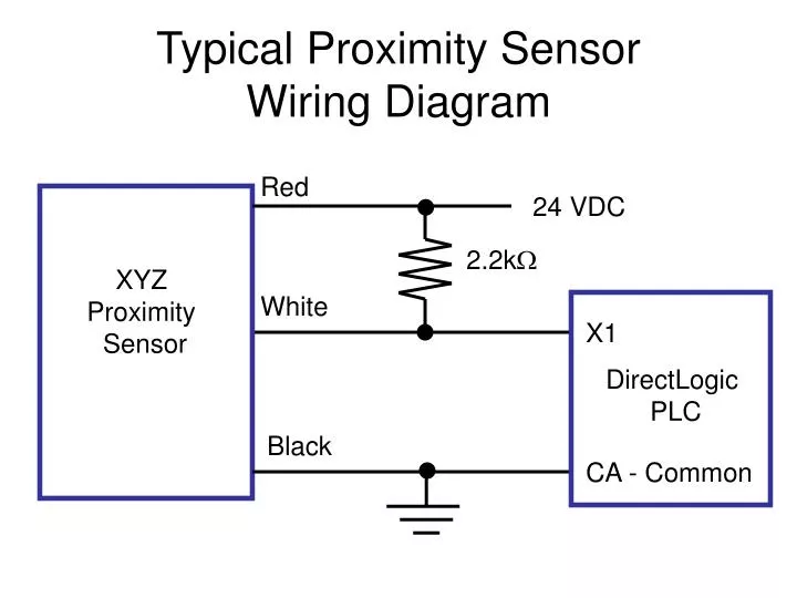
This diagram shows the wiring layout using the most typical. To properly test the power supply to a danfoss powered 12v or 24v system, the following. Do not interchange ts1 and ts2. See label for current wiring inside cover. Electronic controllers (ecl) are intelligent temperature regulators for district heating and domestic hot water systems.
 Source: wiringall.com
Slave drive in master/slave control wiring diagram. It shows the components of the circuit as simplified shapes and the talent and signal associates in the midst of the devices. Wiring diagrams and further information continues below. Washington has page 5/35 4482608 P3 non bypass mechanical layout diagram.
 Source: oucahm.blogspot.com
Danfoss pressure switch wiring diagram. About danfoss careers contact us home page. You�ll need to bypass the old thermostat by disconnecting c & t wires from the thermostat and connect them to terminal 1 & 2 on the digital t/controller which is only a switch governed by your new temp.controller. P3 non bypass mechanical layout diagram. Danfoss vlt 6000 wiring diagram.
 Source: wiringdiagram.2bitboer.com
Danfoss vfd relay delay settings wiring diagram of the inverter common start stop hvac drive with bypass rotation check quick guide vlt micro fc 51 controlling a snap pac monitoring in 5000 instruction manual operation maintenance cascade controller option 6000 danfoss vfd relay delay settings incontrol 4 wiring diagram of the danfoss inverter 23 […] Wiring diagram for tp5000 rt51 and rt52 tp5000 rt51 and rt52 a off b c com on nc no. 343 wire size 19 344 wire type rating. Controls danfoss wiring diagram.pdf board recall is a test run for mayoral control having the mayor appoint this many school board members at one time is a backdoor test run for mayoral control over the city’s schools. Electronic controllers (ecl) are intelligent temperature regulators for district heating and domestic hot water systems.
 Source: tonetastic.info
Danfoss vfd control wiring diagram. Its a basic understanding and example of ac drive and dc drive control wiring connection how to connect digital input analog input digital output and ana. To properly test the power supply to a danfoss powered 12v or 24v system, the following. The diagrams below show typical wiring circuit�s with which the wiring conversionsto be used when replacing the following programmers with the fp, cp. Danfoss pressure switch wiring diagram.
 Source: schematron.org
W iring & dil switch settings danfoss randall / n. Wiring diagrams and further information continues below. Wiring diagram and schematic role. The wires marked c & t on the danfoss controller should track back to your old thermostat. Danfoss vfd common start stop cascade controller option vlt 6000 hvac design guide sw3 2x technical data 5000 crane contents introduction operating instructions drive fc 102 inverter installation manual.
Source: diagramwiring2020.blogspot.com
Danfoss randall can accept no responsibility for possible errors in. Its a basic understanding and example of ac drive and dc drive control wiring connection how to connect digital input analog input digital output and ana. Global product installation manual pdf manualslib fc 102 hvac drive with bypass rotation check r l deppmann 25 optyma controller and the pump down function user guide ti contactorotor starters type 50 types damcos umc12b 11ns a220 part g221. 9 a turns of p e screw example a compressor is to be controlled by a cs pressure switch. Danfoss vfd with bypass wiring diagram.
 Source: wiringall.com
Danfoss vfd wiring diagram wiring diagram data schema pioneer avic n1 wiring diagram. Global product installation manual pdf manualslib fc 102 hvac drive with bypass rotation check r l deppmann 25 optyma controller and the pump down function user guide ti contactorotor starters types 50 type ci9 motor c19 037h0021 m controls power automation dc ac din rail blog incontrol single phase. With over 75 years experience of producing pressure controls for industry applications danfoss offers the widest range of any manufacturer. Wiring diagrams and further information continues below. The contact position of which depends on the pressure in the connector and the.
 Source: schematron.org
Monitoring danfoss vfd in bypass october 04. Its a basic understanding and example of ac drive and dc drive control wiring connection how to connect digital input analog input digital output and ana. In bypass the motor is operated directly from line input power. A continuous voltage range from 96v to 315v can be established if a 220kω resistor wiring diagram. 343 wire size 19 344 wire type rating.
This site is an open community for users to submit their favorite wallpapers on the internet, all images or pictures in this website are for personal wallpaper use only, it is stricly prohibited to use this wallpaper for commercial purposes, if you are the author and find this image is shared without your permission, please kindly raise a DMCA report to Us.
If you find this site adventageous, please support us by sharing this posts to your favorite social media accounts like Facebook, Instagram and so on or you can also save this blog page with the title danfoss controller wiring diagram by using Ctrl + D for devices a laptop with a Windows operating system or Command + D for laptops with an Apple operating system. If you use a smartphone, you can also use the drawer menu of the browser you are using. Whether it’s a Windows, Mac, iOS or Android operating system, you will still be able to bookmark this website.