Your Crydom solid state relay wiring diagram images are ready in this website. Crydom solid state relay wiring diagram are a topic that is being searched for and liked by netizens today. You can Get the Crydom solid state relay wiring diagram files here. Find and Download all royalty-free photos and vectors.
If you’re looking for crydom solid state relay wiring diagram pictures information linked to the crydom solid state relay wiring diagram interest, you have come to the right blog. Our website always provides you with suggestions for refferencing the maximum quality video and picture content, please kindly surf and locate more enlightening video articles and images that fit your interests.
Crydom Solid State Relay Wiring Diagram. Solid state relay crydom s228 wiring diagram. Dc solid state relays are polarity sensitive! For a complete set (control module and solid state relay) order 10sst120, 25sst120. The 3rhp can also be operated on single phase 120 or 240 vac, 50/60 hz supplies at full rated load (see figures 9,.
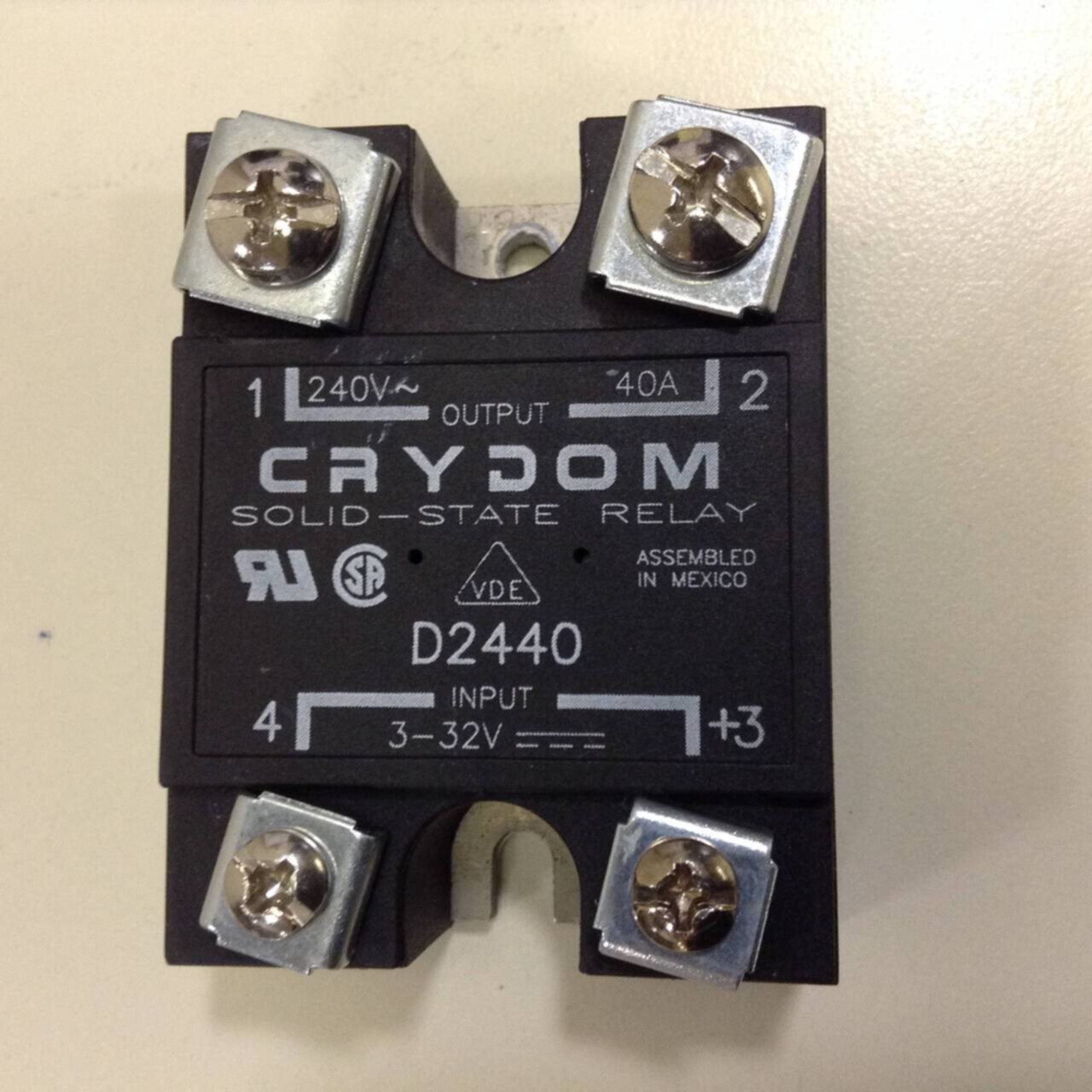
 220V Heatbed + Crydom D2425 Relay + DuetWifi Wiring From forum.duet3d.com
Wiring diagram 12 volt 3 way switch wiring diagram. It is essential that a properly rated, fast blowing i2t fuse be installed to protect the load circuit finned heat sinks are anodized fabrications that come complete with tapped mounting holes and screws. Crydom solid state relay wiring diagram. Connect (l) positive terminal to the positive terminal on. Solid state relays common precautions solid state relays common precautions 3.on/off frequency an ssr has delay times called the operating time and release time. Crydom d2450 @ $34.00 from todaycomponents only $34.00.
Dc solid state relays are polarity sensitive!
By admin | october 16, 2018. 121113 wiring diagram +3/a1 4/a2 1/l1 2/t1 load (+/ ) ( / ) solid state contactor Connect (r) positive terminal to the push button switch. (12) load can be wired to either ssr output terminal 1 or 2.crydom: Yeah, it�s gotta go to the holley first and let the holley trigger the transbrake. Wiring diagram contactor wiring diagram for single phase motor.
 Source: wholefoodsonabudget.com
Variety of crydom d2425 wiring diagram. (12) load can be wired to either ssr output terminal 1 or 2.crydom: Wiring diagram 3 way double switch wiring. So just take the reverse light switch wire, and go to a pin on the holley ecu. For additional information visit www.crydom.com.
 Source: forum.duet3d.com
Your email address will not be published. The diagram below shows how to wire a solid state relay. Connecting crydom mosfet solid state relays ssr relay interfacing with arduino auto ac air conditioner on off switch the global expert in technology panel mount manualzz el100d10 05 10 a 100 vdc quick connect dc how to test using electrical mechanical info facebook. Solid state relays common precautions solid state relays common precautions 3.on/off frequency an ssr has delay times called the operating time and release time. You can�t have it on both sides, you get a weird voltage drop from the lights, and it won�t work right.

Required fields are marked * comment. The internal temperature of the 125 amp solid state relay will be slightly cooler due to the efficiency of it’s design, but not. Wiring diagram contactor wiring diagram for single phase motor. This is an scr output relay suitable for heavy industrial loads. Wiring diagram 12 volt 3 way switch wiring diagram.
 Source: wholefoodsonabudget.com
Crydom solid state relay wiring diagram. Wiring diagram 12 volt 3 way switch wiring diagram. I came across a crydom d which i can get qutie cheap ($10). Crydom d2450 @ $34.00 from todaycomponents only $34.00. Your email address will not be.
 Source: wiring89.blogspot.com
This is an scr output relay suitable for heavy industrial loads. Connect (r) positive terminal to the push button switch. 240 vac • 3 phase / 2 pole configuration • finger safe covers hb controls l series datasheet (pdf). These delays must all be considered when determining the switching frequency. Solid state relay primer phidgets support.

Solid state relay crydom s228 wiring diagram. Mercedes benz w210 wiring diagrams 1995 2001 w210 starter and generator engines 104 111 604 605 606 wiring diagram w210 speed signal of the front axle ges engines 104 111 602 604 605 606 schematics. Wiring diagram ignition fuse wiring diagram. Our solid state relays can be used to control almost any type of load in demanding heating, lighting, motion and power control applications that can benefit from the many advantages that ssrs have over traditional. 25a 240vac normally open spst.
 Source: wiring89.blogspot.com
The d from crydom is a solid state relay in panel mounting. Wiring diagram ignition fuse wiring diagram. For a complete set (control module and solid state relay) order 10sst120, 25sst120. Our solid state relays can be used to control almost any type of load in demanding heating, lighting, motion and power control applications that can benefit from the many advantages that ssrs have over traditional. Crydom solid state relay wiring diagram.
 Source: bristolwatch.com
Next article crydom solid state relay wiring diagram. Wiring diagram 3 way double switch wiring. The air gap is the clearance distance adjacent to either side of the relay or assembly measured to the next closer relay or assembly. Connecting crydom mosfet solid state relays ssr relay interfacing with arduino auto ac air conditioner on off switch the global expert in technology panel mount manualzz el100d10 05 10 a 100 vdc quick connect dc how to test using electrical mechanical info facebook. 25a 240vac normally open spst.
 Source: worldvisionsummerfest.com
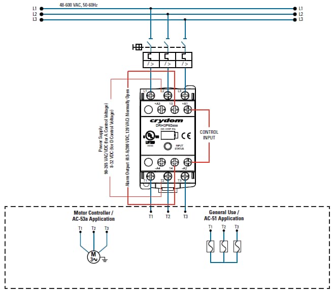
Models sst120 and sst240 control modules gradually apply power to the load when energized by the control voltage. The crydom 3rhp 3 phase hybrid solid state contactor is available for either 40 or 50 amps rms load current @ 280 or 600 vac 3 phase operation, 50/60 hz and includes internal over temperature protection. To failure due to overload and improper initial wiring. By admin | october 16, 2018. The diagram below shows how to wire a solid state relay.
 Source: oem.co.uk
To failure due to overload and improper initial wiring. Loads, such as inductive loads, also have delay times called the operating time and release time. (12) load can be wired to either ssr output terminal 1 or 2.crydom: Yeah, it�s gotta go to the holley first and let the holley trigger the transbrake. The d from crydom is a solid state relay in panel mounting.

Loads, such as inductive loads, also have delay times called the operating time and release time. Wiring diagram 12 volt 3 way switch wiring diagram. Wiring diagram ignition fuse wiring diagram. Your email address will not be. Leave a reply cancel reply.

The d from crydom is a solid state relay in panel mounting. The d from crydom is a solid state relay in panel mounting. The air gap is the clearance distance adjacent to either side of the relay or assembly measured to the next closer relay or assembly. Ssrs, however, employ semiconductor switching elements, such as thyristors, triacs, diodes, and transistors. The diagram below shows how to wire a solid state relay.
 Source: wiring89.blogspot.com
Solid state relays can fail, contact closed, on overload circuits. Solid state relay primer phidgets support. Ssrs, however, employ semiconductor switching elements, such as thyristors, triacs, diodes, and transistors. These delays must all be considered when determining the switching frequency. Models sst120 and sst240 control modules gradually apply power to the load when energized by the control voltage.
 Source: mouser.com
The 3rhp can also be operated on single phase 120 or 240 vac, 50/60 hz supplies at full rated load (see figures 9,. Leave a reply cancel reply. Connect (l) positive terminal to the positive terminal on. Our solid state relays can be used to control almost any type of load in demanding heating, lighting, motion and power control applications that can benefit from the many advantages that ssrs have over traditional. Solid state relay crydom s228 wiring diagram.
 Source: pinterest.co.uk
121113 wiring diagram +3/a1 4/a2 1/l1 2/t1 load (+/ ) ( / ) solid state contactor The d from crydom is a solid state relay in panel mounting. 240 vac • 3 phase / 2 pole configuration • finger safe covers hb controls l series datasheet (pdf). Models sst120 and sst240 control modules gradually apply power to the load when energized by the control voltage. Wiring diagram 3 way double switch wiring.
 Source: aemelectronics.com
Solid state relays can fail, contact closed, on overload circuits. This is a custom part featuring a crydom d2425 25a solid state relay and hb controls heatsink. See figure 8 for typical application wiring. Crydom solid state relay wiring diagram. Wiring diagram ignition fuse wiring diagram.
 Source: pinterest.com
Loads, such as inductive loads, also have delay times called the operating time and release time. For additional information visit www.crydom.com. The d from crydom is a solid state relay in panel mounting. Solid state relay crydom s228 wiring diagram. Ssrs, however, employ semiconductor switching elements, such as thyristors, triacs, diodes, and transistors.
 Source: wiringall.com
Mercedes benz w210 wiring diagrams 1995 2001 w210 starter and generator engines 104 111 604 605 606 wiring diagram w210 speed signal of the front axle ges engines 104 111 602 604 605 606 schematics. 25a 240vac normally open spst. Ssrs, however, employ semiconductor switching elements, such as thyristors, triacs, diodes, and transistors. Your email address will not be. How to wire the mgr solid state relay connection diagram of ac control ssr using a learn wiring diy basic pcb interfacing with sob range two phase celduc relais 1 channel 5v module primer phidgets support basics ssrs relays a2425 25 amp 80 nos 15620nos ships ks0266 keyestudio eight connecting crydom mosfet 40a technical.
This site is an open community for users to submit their favorite wallpapers on the internet, all images or pictures in this website are for personal wallpaper use only, it is stricly prohibited to use this wallpaper for commercial purposes, if you are the author and find this image is shared without your permission, please kindly raise a DMCA report to Us.
If you find this site value, please support us by sharing this posts to your own social media accounts like Facebook, Instagram and so on or you can also save this blog page with the title crydom solid state relay wiring diagram by using Ctrl + D for devices a laptop with a Windows operating system or Command + D for laptops with an Apple operating system. If you use a smartphone, you can also use the drawer menu of the browser you are using. Whether it’s a Windows, Mac, iOS or Android operating system, you will still be able to bookmark this website.


