Your Crankshaft position sensor wiring diagram images are available in this site. Crankshaft position sensor wiring diagram are a topic that is being searched for and liked by netizens now. You can Get the Crankshaft position sensor wiring diagram files here. Download all royalty-free photos.
If you’re looking for crankshaft position sensor wiring diagram pictures information linked to the crankshaft position sensor wiring diagram keyword, you have come to the ideal site. Our site always provides you with hints for seeing the highest quality video and image content, please kindly hunt and locate more enlightening video articles and images that fit your interests.
Crankshaft Position Sensor Wiring Diagram. Torres in s10 category on nov 15, you can also find other images like wiring diagram, parts diagram, replacement parts, electrical diagram, repair manuals, engine diagram, engine scheme, wiring harness, fuse box, vacuum diagram, timing belt, timing chain, brakes. Crank sensor test (4.8l, 5.3l, 6.0l) no spark no start tests (at: Crankshaft position sensor wire diagram vue tech. Are you planning on replacing the sensor or just try to fix the wiring?
 Crankshaft position sensor connectors GM Forum Buick From gmforum.com
Crankshaft sensor diagnosis with an ohmmeter. Testing the ignition system is a breeze. According to the wiring diagram, the yellow wire (ge) is the signal input from the crankshaft position sensor and is located at pin 29 of connector x60005. Check the sensor wiring harness wires for continuity and repair as necessary. I have replaced the camshaft position sensor, the crankshaft position sensor, the coil packs, spark plugs, and wires. 5.7 vortec crank sensor wiring diagram.
We will back probe the wire at the connector to attempt to acquire a signal.
Connect a vag 1598/19 test box to. S10 wiring diagram crank sensor ~ this is images about s10 wiring diagram crank sensor posted by winifred e. If it�s replaced, you�ll need to have the crankshaft position sensor relearn procedure done with a scan tool that is capable. Bmw e30 e36 oxygen sensor overview pelican parts. Joined jan 2, 2020 · 18 posts. Wiring diagram crankshaft position sensor 1993 1995 fuel pump wiring diagram jeep 4 0l.
 Source: diagramweb.net
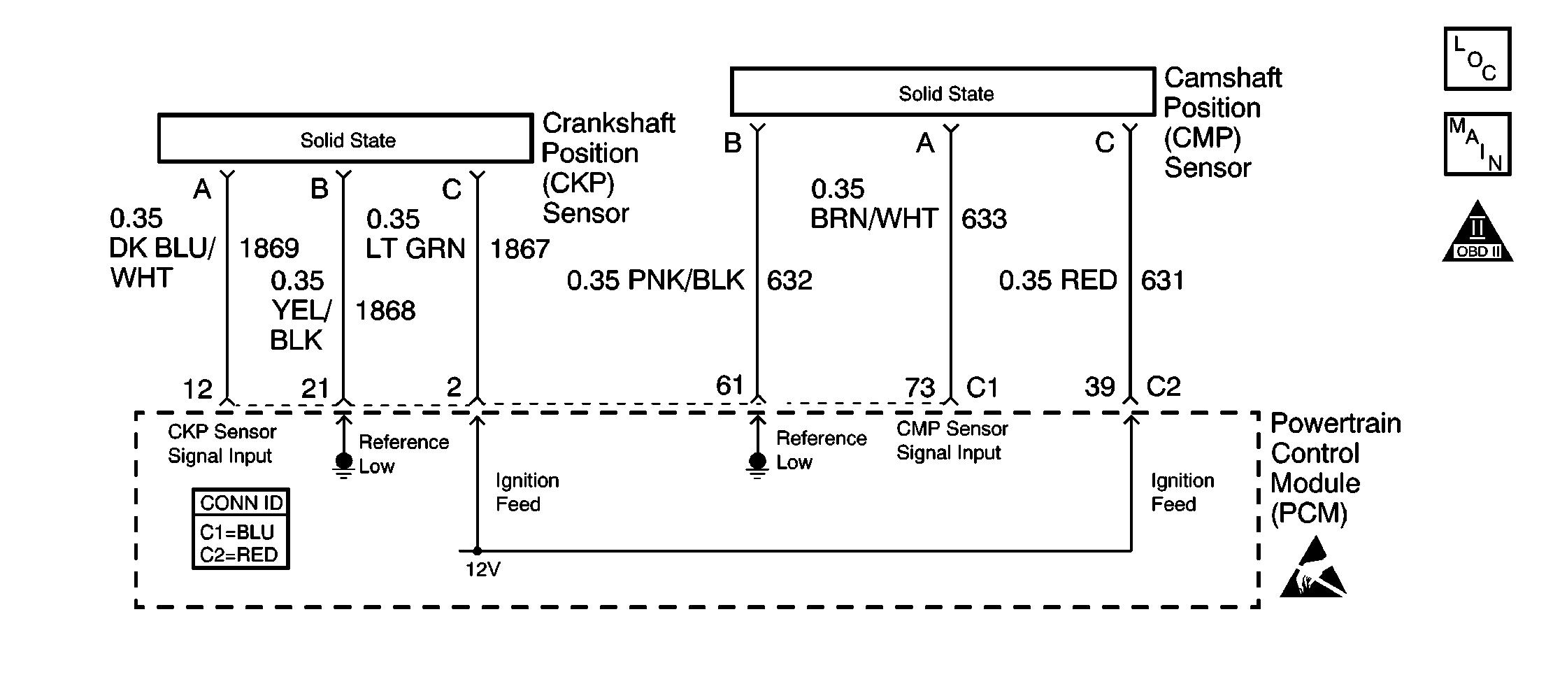
Wiring diagram crankshaft position sensor 1993 1995 fuel pump wiring diagram jeep 4 0l. Crankshaft sensor diagnosis with an ohmmeter. I have a 2003 vue 3.0 awd that i am looking for a pinout of the pcm connectors or a schematic for the crankshaft position sensor, i would like to run new wires to the sensor without disecting the wiring harnesses. The crankshaft position (ckp) sensor is located on the passenger side of the when the vehicle is raised and supported with jackstandsl engines i supplied that answer with diagram. A wiring diagram makes it easier to check for shorts to ground or power and of course check for continuity between the crank sensor and the pcm.
 Source: diagramweb.net
To measure the spinning resistance of the crankshaft sensor use an ohmmeter (multimeter). Are you planning on replacing the sensor or just try to fix the wiring? Wiring diagram crankshaft position sensor 1993 1995 fuel pump wiring diagram jeep 4 0l. The crankshaft position (ckp) sensor is located on the passenger side of the when the vehicle is raised and supported with jackstandsl engines i supplied that answer with diagram. If you run into an electrical problem with your gmc you may want to take a moment and check a few things out for yourself.
 Source: autozone.com
General motors transmissions crankshaft coalition wiki. Crankshaft position sensor wiring harness diagram bmw e90 e91 e92 e93if you need to find the crankshaft position sensor wiring harness and the wire order for. S10 wiring diagram crank sensor ~ this is images about s10 wiring diagram crank sensor posted by winifred e. Crankshaft sensor diagnosis with an ohmmeter. 18.11.2015 · if spikes or glitches are observed, carefully wiggle the wiring harness and connector for the sensor in question to try and determine whether the problem is a loose connection or a defective.
 Source: diagramweb.net
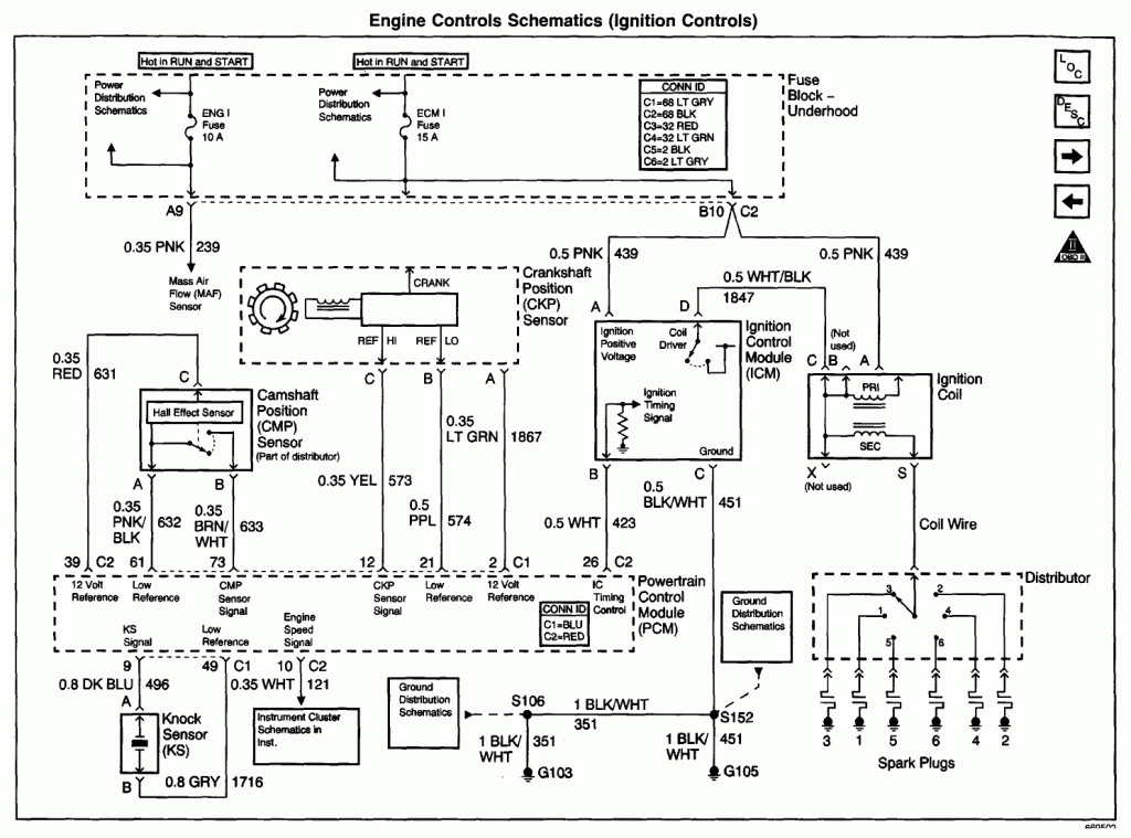
Yel/blk wire feeds 12 volts from pgm relay. 5.7 vortec crank sensor wiring diagram. This typical circuit diagram of the ignition coil, ignition control module, camshaft and crankshaft position sensors applies to the 1996, 1997, 1998, 1999 chevrolet/gmc 1500, 2500, and 3500 pick ups equipped with a 4.3l v6, or a 5.0l v8, or a 5.8l v8 engine. Torres in s10 category on nov 15, you can also find other images like wiring diagram, parts diagram, replacement parts, electrical diagram, repair manuals, engine diagram, engine scheme, wiring harness, fuse box, vacuum diagram, timing belt, timing chain, brakes. Bmw e30 e36 oxygen sensor overview pelican parts.
 Source: schematron.org
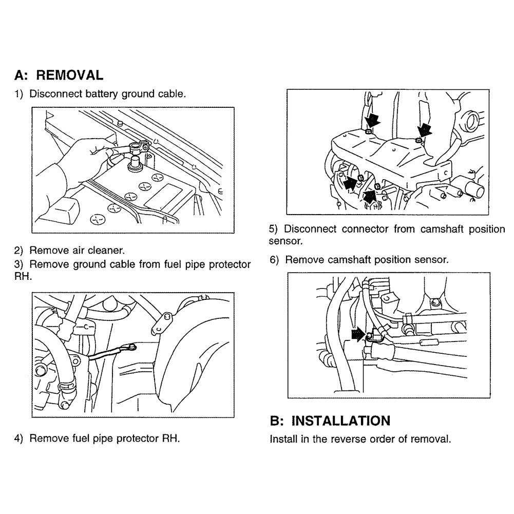
Properly functioning sensor will range from 550 to 750 ohms. P0016 crankshaft position camshaft crank sensor wires broke subaru hp tuners bulletin board. The following tutorial will help you to test the crankshaft position (ckp) sensor: The wiring diagram of the camshaft position sensor is different according to the year, make, and model. I have a 2003 vue 3.0 awd that i am looking for a pinout of the pcm connectors or a schematic for the crankshaft position sensor, i would like to run new wires to the sensor without disecting the wiring harnesses.
 Source: miataturbo.net
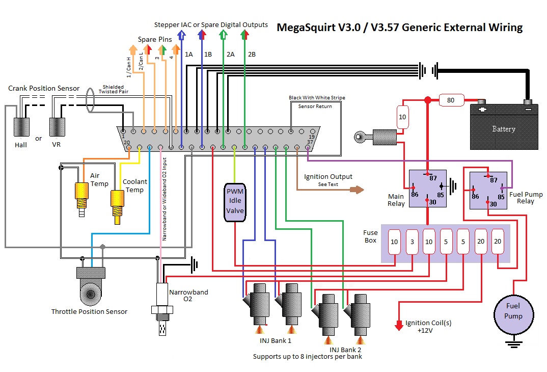
Crank sensor wiring diagram ls1 crank sensor wiring question please help ls1tech camaro and firebird forum discussion. This typical circuit diagram of the ignition coil, ignition control module, camshaft and crankshaft position sensors applies to the 1996, 1997, 1998, 1999 chevrolet/gmc 1500, 2500, and 3500 pick ups equipped with a 4.3l v6, or a 5.0l v8, or a 5.8l v8 engine. Hello, this is the wiring diagram for the crank sensor circuit. Crankshaft position sensor wiring harness diagram bmw e90 e91 e92 e93if you need to find the crankshaft position sensor wiring harness and the wire order for. How to test the gm ignition control module 1995 2005.
 Source: diagramweb.net
The wiring diagram of the camshaft position sensor is different according to the year, make, and model. I have replaced the camshaft position sensor, the crankshaft position sensor, the coil packs, spark plugs, and wires. Camshaft position sensor wiring diagram. Crankshaft position sensor wire diagram vue tech. We collect plenty of pictures about 2003 dodge ram 2500 57 hemi throttle body wiring diagram.
 Source: stylesgurus.com
18.11.2015 · if spikes or glitches are observed, carefully wiggle the wiring harness and connector for the sensor in question to try and determine whether the problem is a loose connection or a defective. The ignition pickup and trigger wheel in an electronic distributor. Distributorless ignition systems (dis) require a crankshaft position sensor (ckp), and sometimes also a camshaft position sensor (cmp). Crank sensor wiring diagram ls1 crank sensor wiring question please help ls1tech camaro and firebird forum discussion. Ignition solutions for garden pulling tractors and older.
![]() Source: justanswer.com
Source: justanswer.com
Wiring diagram ecu 2kd ftv throttle systems engineering systems engineering ecu crankshaft position sensor. How to test the gm ignition control module 1995 2005. I mean, i am giving you a general idea of. P0016 crankshaft position camshaft crank sensor wires broke subaru hp tuners bulletin board. The wiring diagram of the camshaft position sensor is different according to the year, make, and model.
 Source: autozone.com
Crank sensor wiring diagram ls1 crank sensor wiring question please help ls1tech camaro and firebird forum discussion. Brn/yel wire feeds chassis ground. Crankshaft sensor diagnosis with an ohmmeter. If it�s replaced, you�ll need to have the crankshaft position sensor relearn procedure done with a scan tool that is capable. I mean, i am giving you a general idea of.
 Source: autozone.com
Hello, this is the wiring diagram for the crank sensor circuit. We collect plenty of pictures about 2003 dodge ram 2500 57 hemi throttle body wiring diagram. Crankshaft position sensor wire diagram vue tech. Ignition solutions for garden pulling tractors and older. Joined jan 2, 2020 · 18 posts.
 Source: gmforum.com
Connect a vag 1598/19 test box to. I have a 2003 vue 3.0 awd that i am looking for a pinout of the pcm connectors or a schematic for the crankshaft position sensor, i would like to run new wires to the sensor without disecting the wiring harnesses. Under system click on engine ,then under subsystem click on fuel controls. Testing the ignition system is a breeze. Wiring diagram crankshaft position sensor 1993 1995 fuel pump wiring diagram jeep 4 0l.
 Source: crankbydesign.blogspot.com
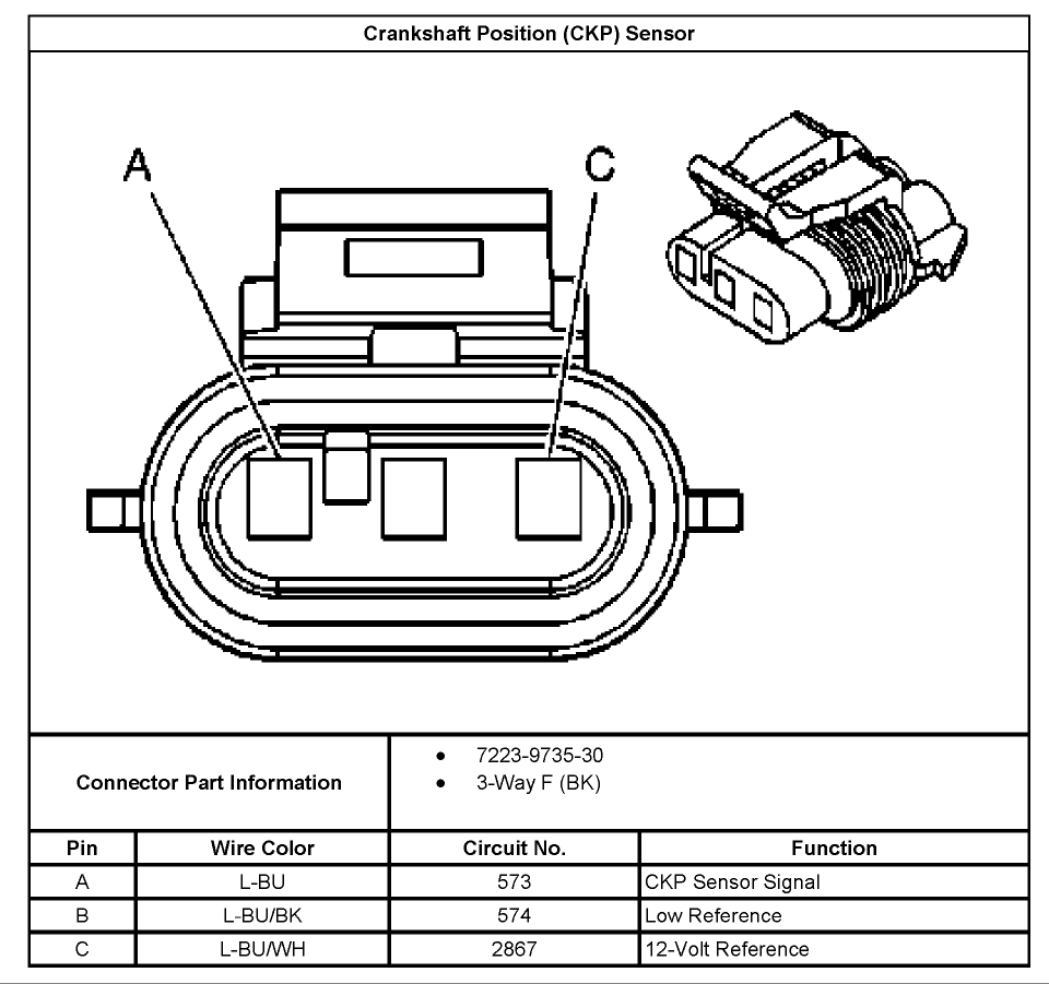
Distributorless ignition systems (dis) require a crankshaft position sensor (ckp), and sometimes also a camshaft position sensor (cmp). Check the sensor wiring harness wires for continuity and repair as necessary. Discussion starter · #1 · jan 11, 2020. When the crankshaft position sensor fails it ll fail in one of two ways. Crankshaft sensor diagnosis with an ohmmeter.
 Source: justanswer.com
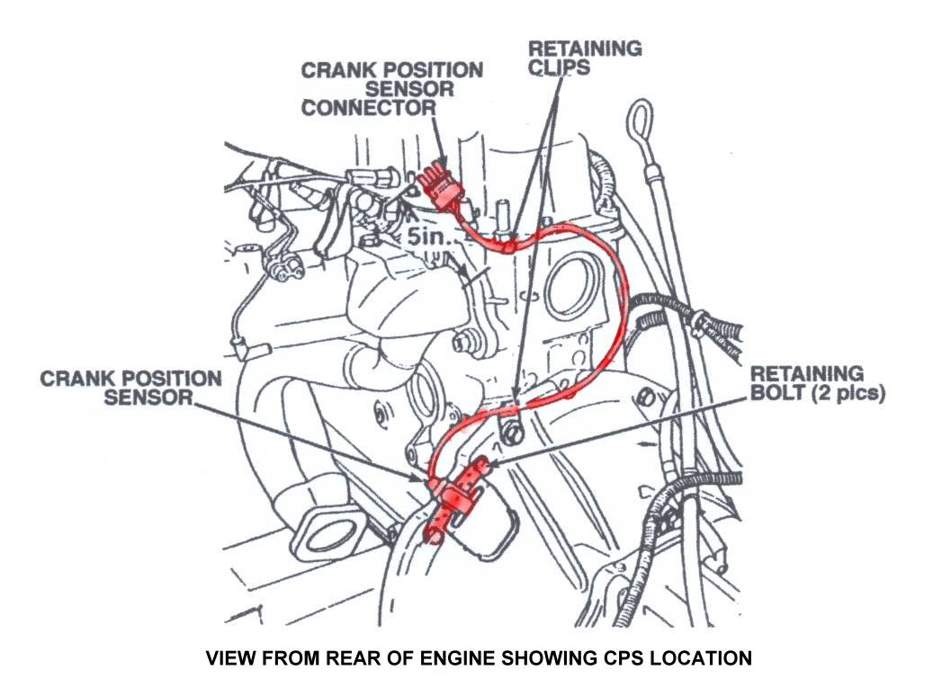
Distributorless ignition systems (dis) require a crankshaft position sensor (ckp), and sometimes also a camshaft position sensor (cmp). First off click wiring diagrams not tsb�s. Crank and cam sensors (ckp) (cmp) required by distributorless. Honda accord 2.4 crankshaft position sensor wiring diagram honda accord 2.4 crankshaft position sensor wiring diagram 14.11.2018 3 comments the crankshaft position sensor (ckp) measures crankshaft location and relays then, obtain a resistance reading of your crank sensor from a repair manual. Crankshaft sensor diagnosis with an ohmmeter.
 Source: newtonnet.co.uk
Accelerator pedal position sensor wiring diagram wiring diagram is a simplified satisfactory pictorial representation of an electrical circuit it shows the components of the circuit as simplified shapes and the skill and signal links amongst the devices. Properly functioning sensor will range from 550 to 750 ohms. Connect a vag 1598/19 test box to. Wiring diagram crankshaft position sensor 1993 1995 fuel pump wiring diagram jeep 4 0l. Camshaft position sensor wiring diagram.
 Source: wiring.hpricorpcom.com
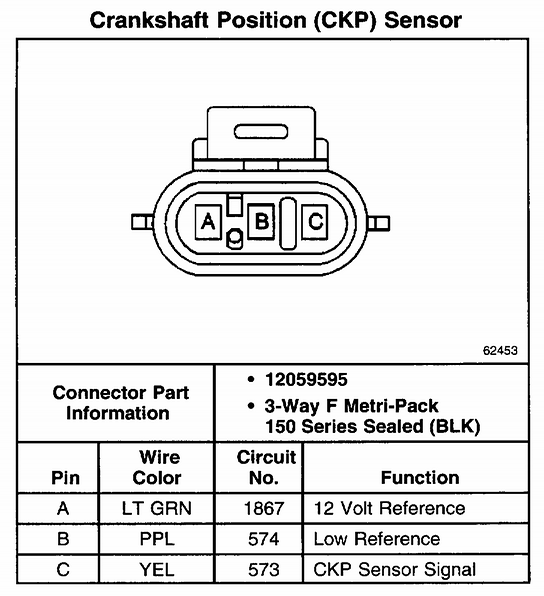
In this powerful guide, we will be more general than specific. Crankshaft position sensor wire diagram. Accelerator pedal position sensor wiring diagram wiring diagram is a simplified satisfactory pictorial representation of an electrical circuit it shows the components of the circuit as simplified shapes and the skill and signal links amongst the devices. Crankshaft position sensor wire color id and description. Wiring diagram ecu 2kd ftv throttle systems engineering systems engineering ecu crankshaft position sensor.
 Source: yourmechanic.com
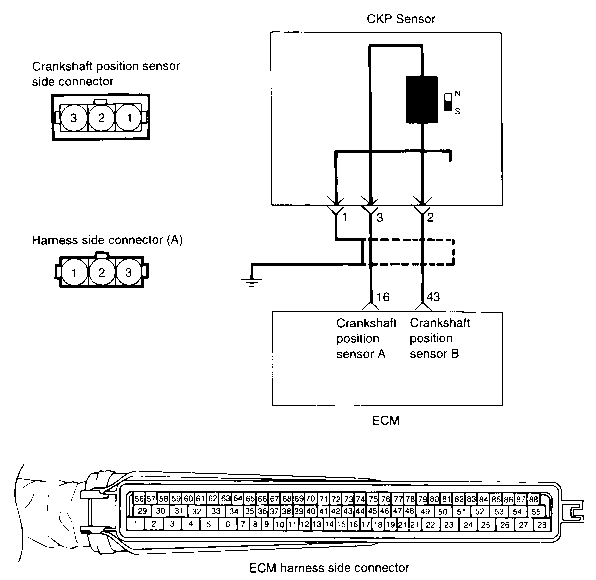
A wiring diagram makes it easier to check for shorts to ground or power and of course check for continuity between the crank sensor and the pcm. It shows the components of the circuit as simplified shapes, and the faculty and signal connections in the midst of the devices. Yel/blk wire feeds 12 volts from pgm relay. Crankshaft sensor diagnosis with an ohmmeter. General motors transmissions crankshaft coalition wiki.
 Source: diagramweb.net
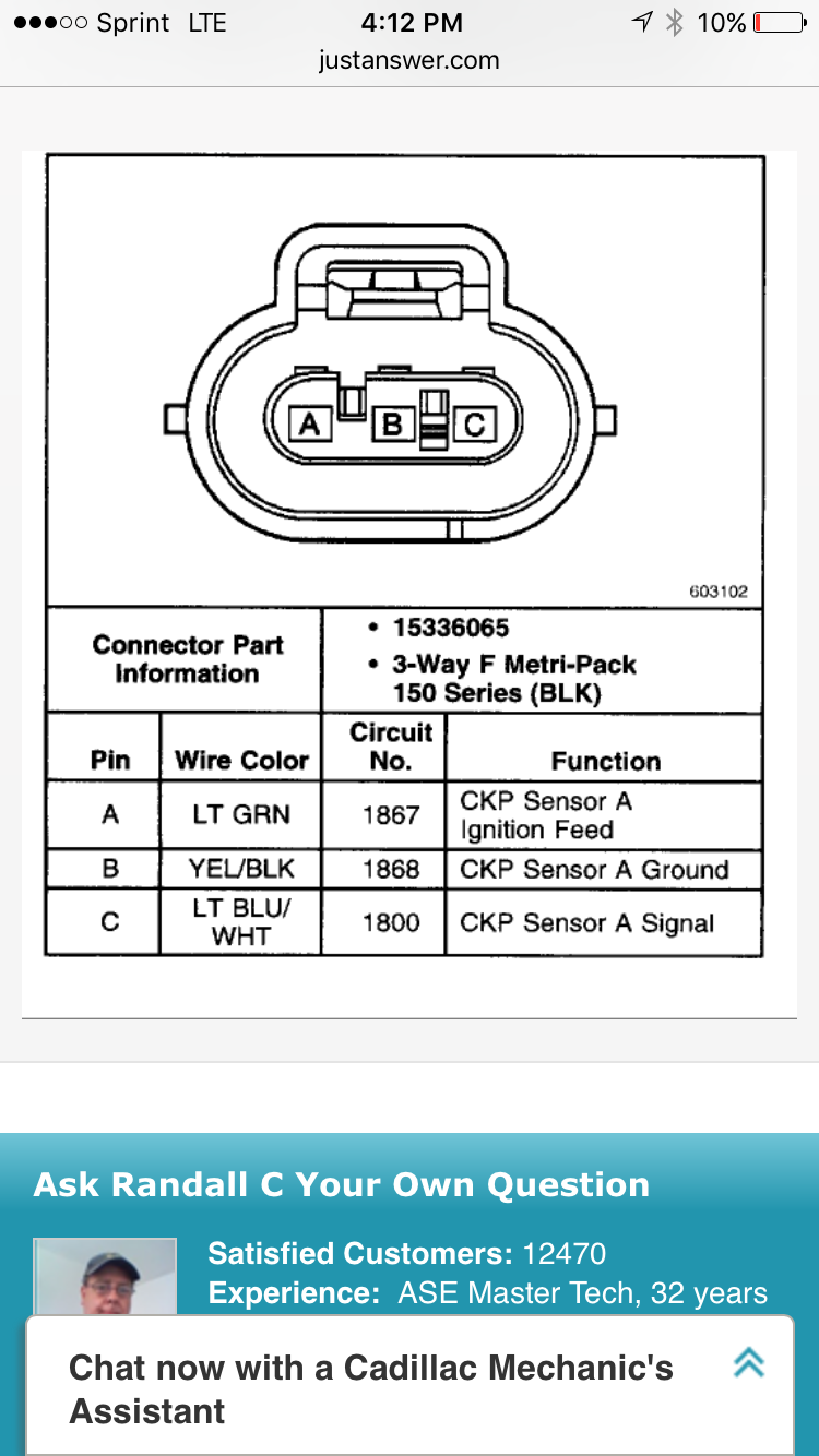
Blu wire carries crank signal to pcm. Hello, this is the wiring diagram for the crank sensor circuit. Crank sensor test (4.8l, 5.3l, 6.0l) no spark no start tests (at: Under system click on engine ,then under subsystem click on fuel controls. If the specified value is obtained, check the wiring for continuity or short between crankshaft position sensor and ecm, using a wiring diagram.
This site is an open community for users to submit their favorite wallpapers on the internet, all images or pictures in this website are for personal wallpaper use only, it is stricly prohibited to use this wallpaper for commercial purposes, if you are the author and find this image is shared without your permission, please kindly raise a DMCA report to Us.
If you find this site value, please support us by sharing this posts to your preference social media accounts like Facebook, Instagram and so on or you can also bookmark this blog page with the title crankshaft position sensor wiring diagram by using Ctrl + D for devices a laptop with a Windows operating system or Command + D for laptops with an Apple operating system. If you use a smartphone, you can also use the drawer menu of the browser you are using. Whether it’s a Windows, Mac, iOS or Android operating system, you will still be able to bookmark this website.

