Your Coolant temperature sensor wiring diagram images are ready. Coolant temperature sensor wiring diagram are a topic that is being searched for and liked by netizens now. You can Find and Download the Coolant temperature sensor wiring diagram files here. Get all free images.
If you’re looking for coolant temperature sensor wiring diagram images information linked to the coolant temperature sensor wiring diagram topic, you have visit the ideal blog. Our website frequently provides you with hints for seeking the maximum quality video and picture content, please kindly hunt and locate more informative video content and images that match your interests.
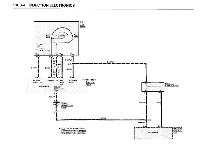
Coolant Temperature Sensor Wiring Diagram. First of all, you have to locate the engine coolant temperature sensor of the car. Key to motronic engine control system wiring diagram picture 11 12 1. The coolant temperature sensor uses a “mushroom” shaped key way where it inserts into the sensors, while the open element intake air temperature sensor uses a “rectangular” connector key way. A typical engine cooling temperature sensor is a negative temperature coefficient (ntc) thermistor, which means its electrical resistance decreases when the temperature increases.
 Gm Engine Coolant Diagram Wiring Diagrams From cars-wiringdiagram.blogspot.com
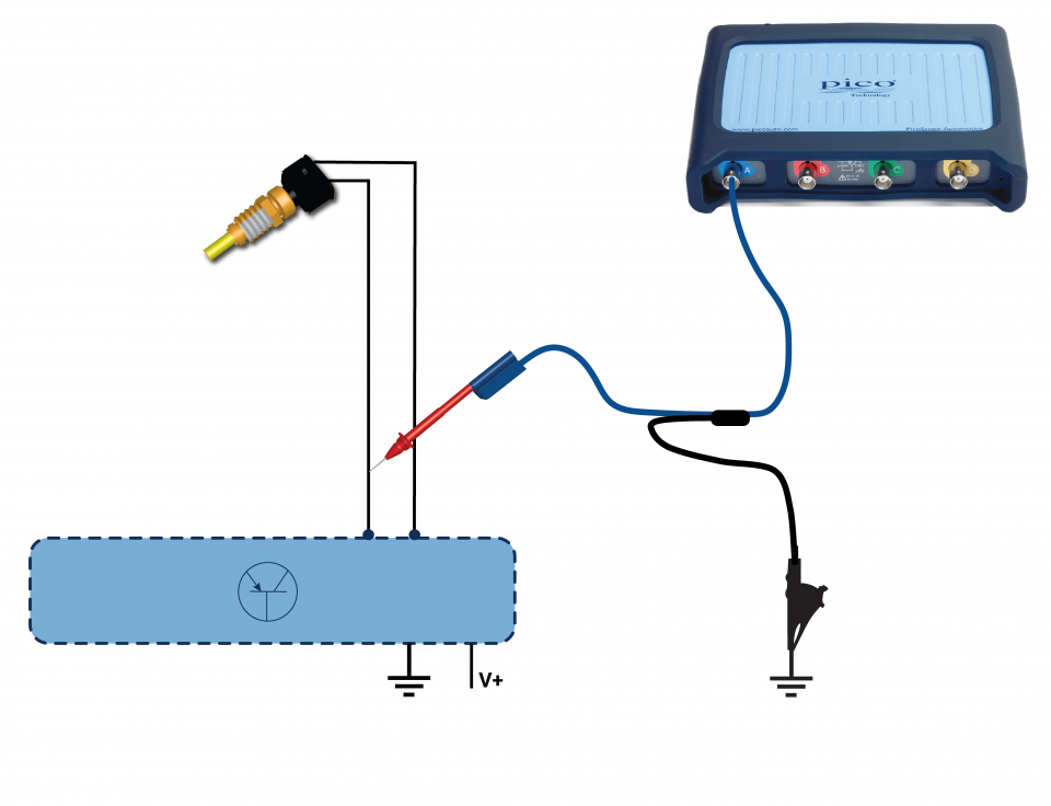
Remove the mounting bolts for the. This coolant temperature sensor test will tell you in just a few most coolant temperature sensors resemble a large nut with an electrical connector on top. This is a rough copy very rough use ur imagination kiddies the top 2 wires are connected to the 2 wire sensor and the bottom wire is connected to the single wire sensor. Buy in monthly payments with affirm on orders over $50. The coolant temp sensor has two units in one g62 g2 g62 is connected to the ecu via browngreen wire at t121104 at ecu and bluebrown wire at t121112 at ecu. The wiring diagram of the coolant temperature sensor is based on year, make, and model.
Coolant temperature sensor wiring diagram.
Toyota rav4 service manual engine coolant temperature circuit diagnostic trouble code chart sfi system 2az fe mechanical. The higher the coolant temperature, the lower will be the voltage. Coolant temperature sensor plug e. This is a rough copy very rough use ur imagination kiddies the top 2 wires are connected to the 2 wire sensor and the bottom wire is connected to the single wire sensor. The coolant temp sensor for the pcm has two wires and is located near the thermostat. But if you insist ,you can find free wiring diagram�s here.
 Source: faceitsalon.com
Coolant temp sensor plug, engine coolant temperature sensor plug, ect plug, water temperature sensor plug associated subaru part numbers: Dakota 5.2 coolant temp sensor wiring diagram. Assuming this is not a diesel engine. Then remove the connector and check it for corrosion. E windshield wiper switch g.
 Source: justanswer.com
Coolant temperature sensor wiring diagram wiring diagram is a simplified enjoyable pictorial representation of an electrical circuitit shows the components of the circuit as simplified shapes and the gift and signal friends between the devices. If you find 5.0 volts, there�s a break after that point, as in the sensor, the connector terminals, or the ground wire. Assuming this is not a diesel engine. The coolant temp sender for the gauge has one wire, dark green. Testing engine coolant temperature sensor.
 Source: atkinsjewelry.blogspot.com
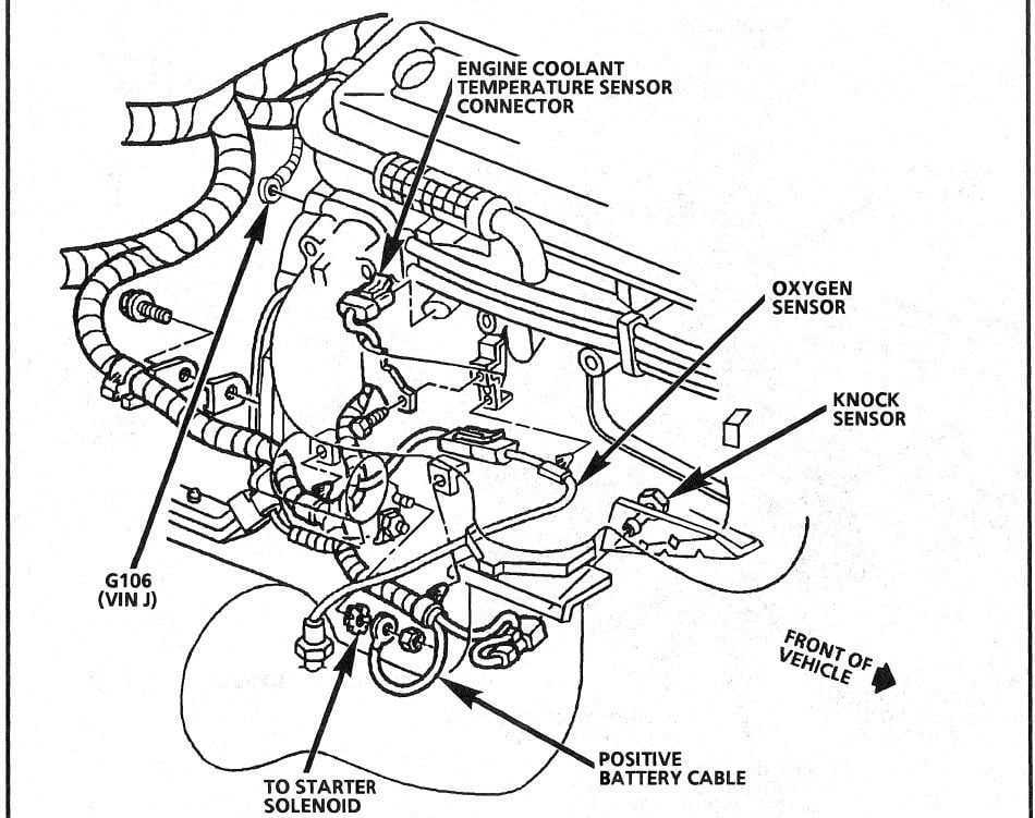
On both the v6 4 3 l vortec engine and the 4 8 l 5 3 l and 6 0 l v 8 engines they locate the coolant temperature sensor on the driver side cylinder head. Then remove the connector and check it for corrosion. The wiring diagram of the coolant temperature sensor is based on year, make, and model. Coolant temperature sensor wiring diagram. The coolant temp sender for the gauge has one wire, dark green.
 Source: kovodym.blogspot.com
1 2 3 wire coolant temperature sensor wiring diagram. Interconnecting wire routes may be shown. 800 x 600 px source. The wiring diagram shows the relay mode when the energizing circuit is off. 7 54 throttle position tp sensor 7 69 ambient temperature.
 Source: autozone.com
On dakota 5.2 coolant temp sensor wiring diagram. Toyota rav4 service manual engine coolant temperature circuit diagnostic trouble code chart sfi system 2az fe mechanical. Remember, the ground wire is shared with other sensors, so if it has a break, you�ll have multiple diagnostic fault codes sets related to them. The higher the coolant temperature, the lower will be the voltage. When you open the hood of the car, you can find the ect sensor in different locations depending upon the make and model of your car.
 Source: diagramweb.net
Check that radiator reservoir bottle is full and radiator itself is filled to top. The other wire, brown/white, goes to a common splice labeled as #269. That one is in the left cylinder head between the first two spark plus. Key to motronic engine control system wiring diagram picture 11 12 1. G2 is connected to the temp gauge in the cluster via a lilac wire.
Source: diagramresource.blogspot.com
Wiring sensiron shtxx temperature sensor w/d python | 14core.com. Toyota 4runner engine coolant temperature receiver gauge malfunction meter system service manual. The other wire, brown/white, goes to a common splice labeled as #269. Coolant temperature sensor wiring diagram wiring diagram is a simplified enjoyable pictorial representation of an electrical circuit. The higher the coolant temperature, the lower will be the voltage.
 Source: wiringforums.com
The coolant temp sensor has two units in one g62 g2 g62 is connected to the ecu via browngreen wire at t121104 at ecu and bluebrown wire at t121112 at ecu. This is a rough copy very rough use ur imagination kiddies the top 2 wires are connected to the 2 wire sensor and the bottom wire is connected to the single wire sensor. When you make use of your finger or perhaps the actual circuit with your eyes, it is easy to mistrace the circuit. The coolant temp sensor has two units in one (g62 & g2) g62 is connected to the ecu via brown/green wire (at t121/104 at ecu) and blue/brown wire (at t121/112 at ecu). On dakota 5.2 coolant temp sensor wiring diagram.
 Source: wiringview.co
Toyota 4runner engine coolant temperature receiver gauge malfunction meter system service manual. Buy in monthly payments with affirm on orders over $50. The wiring diagram of the coolant temperature sensor is based on year, make, and model. Check that radiator reservoir bottle is full and radiator itself is filled to top. Many cars have more than one coolant temperature sensor.
 Source: cars-wiringdiagram.blogspot.com
This is a rough copy very rough use ur imagination kiddies the top 2 wires are connected to the 2 wire sensor and the bottom wire is connected to the single wire sensor. Wiring diagram of temperature sensor figure 6 exhibits the connections scientific. First of all, you have to locate the engine coolant temperature sensor of the car. Do not put it to chassis ground). Toyota 4runner engine coolant temperature receiver gauge malfunction meter system service manual.
 Source: carlosvicentederoux.org
Toyota rav4 service manual engine coolant temperature circuit diagnostic trouble code chart sfi system 2az fe mechanical. The higher the coolant temperature, the lower will be the voltage. E8 on the subaru wiring diagram. A typical engine cooling temperature sensor is a negative temperature coefficient (ntc) thermistor, which means its electrical resistance decreases when the temperature increases. Coolant temperature sensor wiring diagram.
 Source: bimmerforums.com
The connector and sensor are located in the middle of the valve cover in the center of the top of the engine. Wiring diagram of temperature sensor figure 6 exhibits the connections scientific. Toyota rav4 service manual engine coolant temperature circuit diagnostic trouble code chart sfi system 2az fe mechanical. 800 x 600 px source. Remove the mounting bolts for the.
 Source: dentistmitcham.com
Buy in monthly payments with affirm on orders over $50. The higher the coolant temperature, the lower will be the voltage. 1993 1995 iat and ect sensor wiring diagram jeep 4 0l. Check that radiator reservoir bottle is full and radiator itself is filled to top. Coolant temp sensor plug, engine coolant temperature sensor plug, ect plug, water temperature sensor plug associated subaru part numbers:
 Source: easywiring.info
Then remove the connector and check it for corrosion. E windshield wiper switch g. 1993 1995 iat and ect sensor wiring diagram jeep 4 0l. 800 x 600 px source. Coolant temperature sensor wiring diagram.
 Source: modifry.com
The ipc receives a serial data message from the pcm/ecm indicating the engine coolant temperature. T engine coolant temperature sensor and thermometer. Testing engine coolant temperature sensor. The other wire, brown/white, goes to a common splice labeled as #269. This is a rough copy very rough use ur imagination kiddies the top 2 wires are connected to the 2 wire sensor and the bottom wire is connected to the single wire sensor.
 Source: clublexus.com
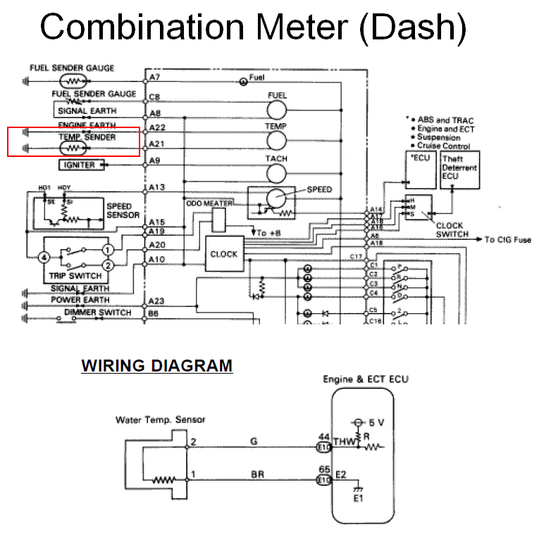
If the wiring does not work as indicated in step 4 third bullet, check for an open in the yellow signal wire or a disconnected or corroded ect sensor connector, see figure 1 or the downloaded wiring diagram. The tip of the ect sensor protrudes into one of the cooling system passages and is immersed in coolant. Coolant temperature sensor wiring diagram wiring diagram is a simplified enjoyable pictorial representation of an electrical circuitit shows the components of the circuit as simplified shapes and the gift and signal friends between the devices. The average cost for a subaru forester engine coolant temperature sensor the technician will unplug the electrical connector from the sensor prior to removal. Assuming you have a 1g ecu the yellow/green goes to ecu pin 20 and the green/black goes to ecu pins 17 & 24 as well as a few of the other sensor�s ground wire pins (note:
Source: tianpinyt.blogspot.com
The ipc receives a serial data message from the pcm/ecm indicating the engine coolant temperature. Testing engine coolant temperature sensor. The wiring i sent you already will help with the coolant temp sensor. The average cost for a subaru forester engine coolant temperature sensor the technician will unplug the electrical connector from the sensor prior to removal. 1 trick that we 2 to printing a similar wiring plan off twice.
 Source: kovodym.blogspot.com
The tip of the ect sensor protrudes into one of the cooling system passages and is immersed in coolant. The ipc receives a serial data message from the pcm/ecm indicating the engine coolant temperature. Coolant temperature sensor wiring diagram wiring diagram is a simplified enjoyable pictorial representation of an electrical circuit. When you make use of your finger or perhaps the actual circuit with your eyes, it is easy to mistrace the circuit. Testing engine coolant temperature sensor.
This site is an open community for users to do submittion their favorite wallpapers on the internet, all images or pictures in this website are for personal wallpaper use only, it is stricly prohibited to use this wallpaper for commercial purposes, if you are the author and find this image is shared without your permission, please kindly raise a DMCA report to Us.
If you find this site value, please support us by sharing this posts to your favorite social media accounts like Facebook, Instagram and so on or you can also bookmark this blog page with the title coolant temperature sensor wiring diagram by using Ctrl + D for devices a laptop with a Windows operating system or Command + D for laptops with an Apple operating system. If you use a smartphone, you can also use the drawer menu of the browser you are using. Whether it’s a Windows, Mac, iOS or Android operating system, you will still be able to bookmark this website.


