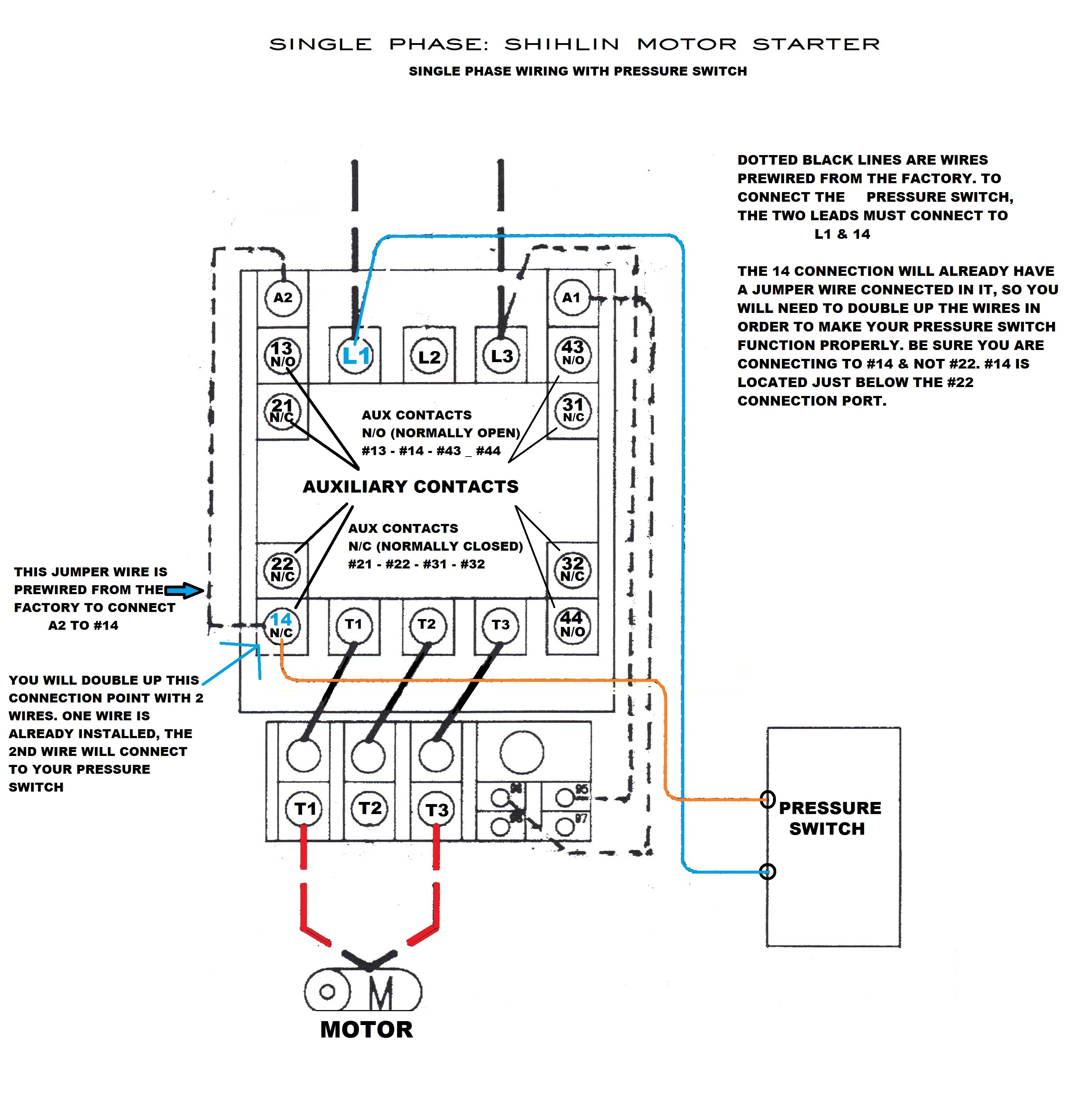
Your Control 4 wiring diagram images are ready. Control 4 wiring diagram are a topic that is being searched for and liked by netizens today. You can Download the Control 4 wiring diagram files here. Download all free vectors.
If you’re searching for control 4 wiring diagram images information connected with to the control 4 wiring diagram topic, you have pay a visit to the right blog. Our website frequently provides you with suggestions for downloading the maximum quality video and image content, please kindly search and locate more enlightening video content and images that fit your interests.
Control 4 Wiring Diagram. Seenote#4 for 3 phase wiring denotes wire to be moved for 3 phase conversion. Battery positive cable, voltage sensing wire, and ignition wire. Emcp 4 2 wiring diagram ~ hello friends our site, this is images about emcp 4 2 wiring diagram posted by brenda botha in emcp category on nov 16, you can also find other images like wiring diagram, parts diagram, replacement parts, electrical diagram, repair manuals, engine diagram, engine scheme, wiring harness, fuse box, vacuum diagram, timing belt, timing. 5 emcp and electrical diagrams.
 Control 4 Wiring Diagram Collection From dentistmitcham.com
For additional powerflex 4 and 40 data and general drive information, refer to wiring and grounding guidelines for pwm ac drives the block diagram. Honeywell thermostat wiring diagram 4 wire source. Control 4 switch wiring diagram wiring diagram and schematics control4 electrical wiring home automation You can download all the image about home and design for free. They can be used as a guide when wiring the controller. Diy enthusiasts use wiring diagrams but they are also common in home building and auto repair.
Wiring diagrams description york® ze/xn series units are convertible single package high efficiency rooftops with a common roof curb for the 3, 4, 5, and 6 ton sizes.
Below are the image gallery of control 4 wiring diagram, if you like the image or like this post please contribute with us to share this post to your social media or save this post in your device. For additional powerflex 4 and 40 data and general drive information, refer to wiring and grounding guidelines for pwm ac drives the block diagram. Wiring diagram courtesy seymour duncan pickups wiring diagram courtesy seymour duncan pickups 4 typical wiring diagrams for push button control stations pilot light selection pilot light selection is based on the following factors; It shows the components of the circuit as streamlined shapes, and the power as well as signal links between the gadgets. 13 abb vd4 wiring diagram.
 Source: schematron.org
The ignition input wire is attached to the engine. You make the decisions when it comes to the technology in your home. Phase 2 l1, l2, l3 ground, when used Diy enthusiasts use wiring diagrams but they are also common in home building and auto repair. Wiring diagram courtesy seymour duncan pickups wiring diagram courtesy seymour duncan pickups
 Source: tonetastic.info
They can be used as a guide when wiring the controller. For example, a home builder will want to confirm the physical location of electrical outlets and light fixtures using a wiring diagram to avoid costly. Battery positive cable, voltage sensing wire, and ignition wire. To make this circuit work, a 3 way dimmer can be used in place of one, or both of the standard 3 way switches. The red (stoplight) wire must be connected to the cold side of the brake pedal stoplight switch.
 Source: ricardolevinsmorales.com
The black wire is the power supply line to the brake control. Honeywell thermostat wiring diagram 4 wire source. Be advised that wiring the device while power is on may cause damage to the terminal. Online library wiring diagram engine control 4a fe wiring diagram engine control 4a fe when somebody should go to the ebook stores, search launch by shop, shelf by shelf, it is in reality problematic. See the engine control system.
 Source: miloicekaw119.blogspot.com
Disconnect yellow wire from relay 3 terminal 6, and connect to relay 1 terminal 6. For additional powerflex 4 and 40 data and general drive information, refer to wiring and grounding guidelines for pwm ac drives the block diagram. Seenote#4 for 3 phase wiring denotes wire to be moved for 3 phase conversion. It conducts electricity from the engine to the alternator while the. Design, the powerflex 4m ac drive is the smallest and most cost effective member.
 Source: dentistmitcham.com
Emcp 4 2 wiring diagram ~ hello friends our site, this is images about emcp 4 2 wiring diagram posted by brenda botha in emcp category on nov 16, you can also find other images like wiring diagram, parts diagram, replacement parts, electrical diagram, repair manuals, engine diagram, engine scheme, wiring harness, fuse box, vacuum diagram, timing belt, timing. Honeywell thermostat wiring diagram 4 wire source. The ignition input wire is attached to the engine. The red (stoplight) wire must be connected to the cold side of the brake pedal stoplight switch. To make this circuit work, a 3 way dimmer can be used in place of one, or both of the standard 3 way switches.
 Source: pinterest.com
Control 4 wiring diagram from i1.wp.com print the cabling diagram off plus use highlighters to be able to trace the routine. You can download all the image about home and design for free. With touchscreen, keypad, voice, and app access, you can create a smart home that’s uniquely yours. V primary, v secondary only. Mounting plate with four wires of the honeywell large dial thermostat model t87n1026.
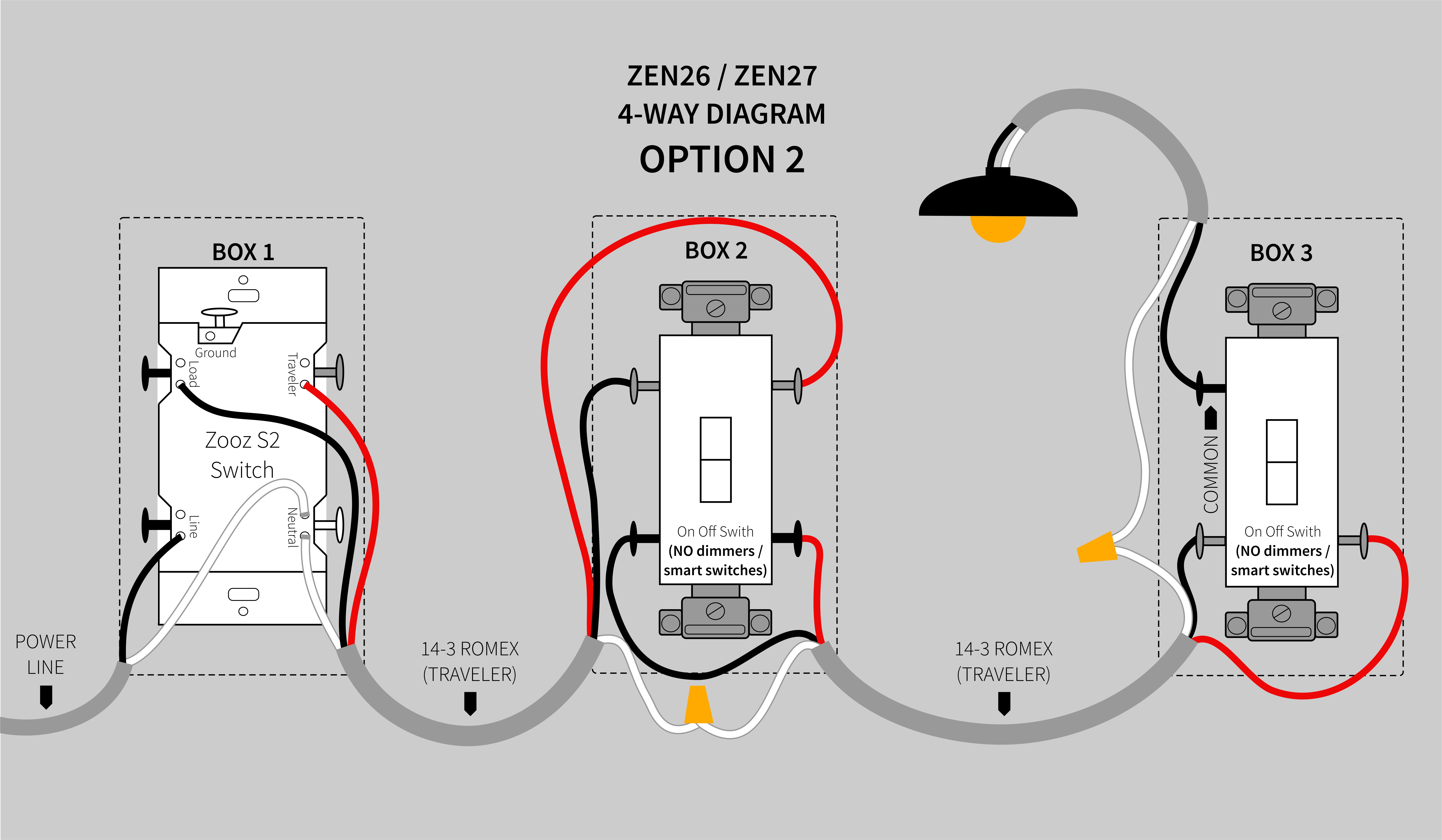 Source: support.getzooz.com
Online library wiring diagram engine control 4a fe wiring diagram engine control 4a fe when somebody should go to the ebook stores, search launch by shop, shelf by shelf, it is in reality problematic. Be advised that wiring the device while power is on may cause damage to the terminal. Voltage, lamp requirements, environment, and cost.4 the voltage of a pilot light must match the voltage supply. Navigate to [new]> [electrical engineering]> [basic electrical] step 3: Variety of control 4 wiring diagram.
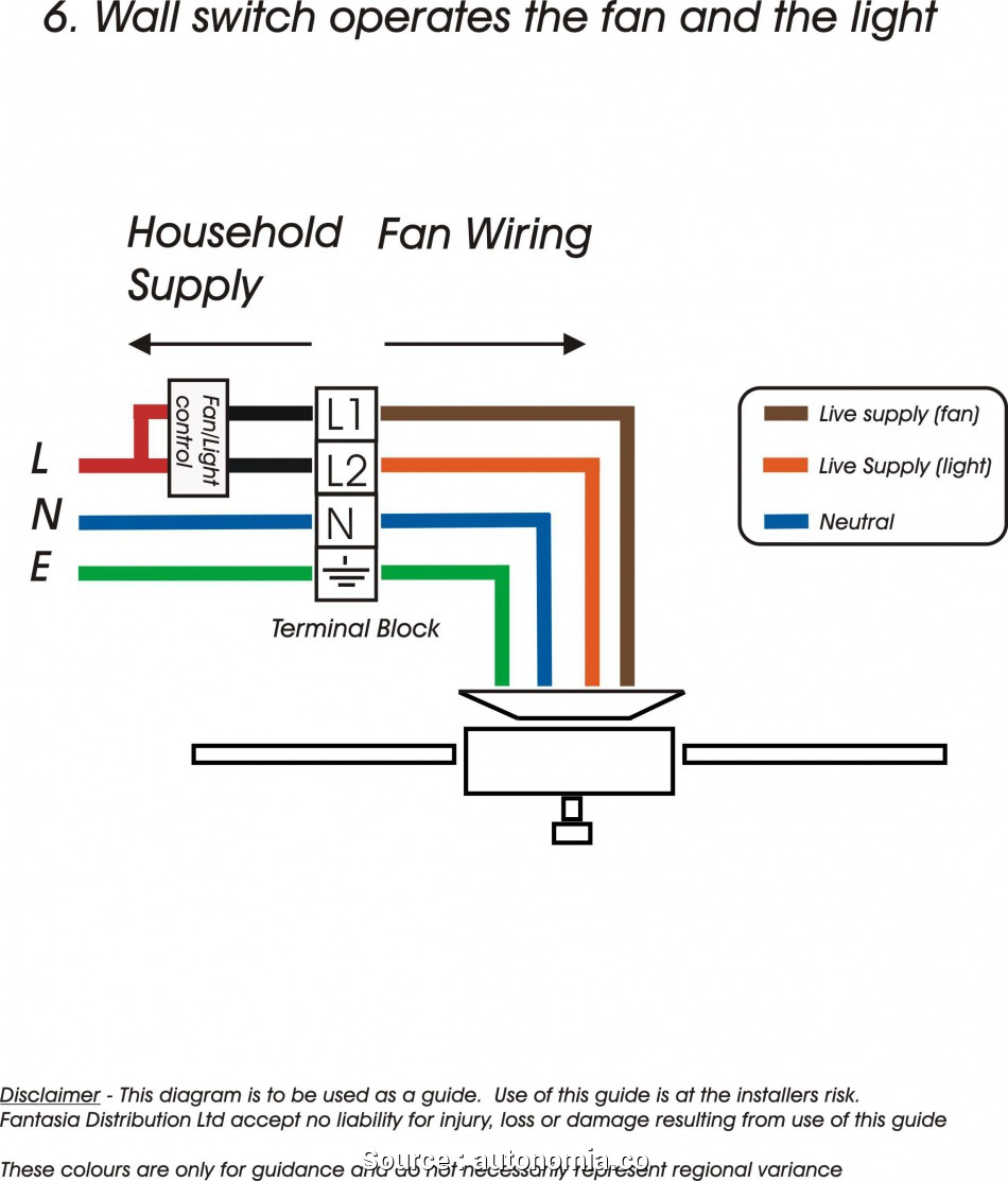 Source: 2020cadillac.com
Wiring diagram courtesy seymour duncan pickups wiring diagram courtesy seymour duncan pickups Control 4 wiring diagram general wiring diagram. Electronic control unit (ecu) 2. They can be used as a guide when wiring the controller. The ignition input wire is attached to the engine.

V primary, v secondary only. You can download all the image about home and design for free. Variety of control 4 wiring diagram. They can be used as a guide when wiring the controller. You make the decisions when it comes to the technology in your home.
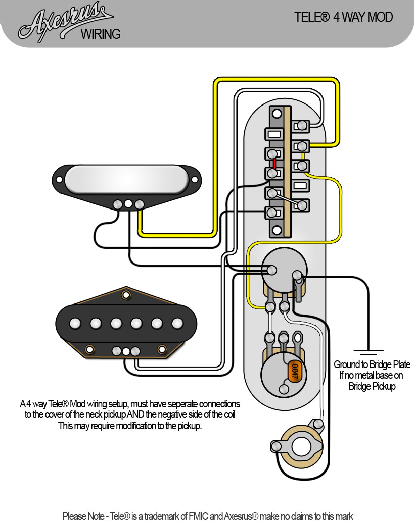 Source: niqqay-lunnia.blogspot.com
It shows the components of the circuit as streamlined shapes, and the power as well as signal links between the gadgets. With touchscreen, keypad, voice, and app access, you can create a smart home that’s uniquely yours. When you employ your finger or perhaps the actual circuit along with your eyes, it is easy to mistrace the circuit. Wiring diagram courtesy seymour duncan pickups wiring diagram courtesy seymour duncan pickups You make the decisions when it comes to the technology in your home.
 Source: pinterest.co.uk
13 abb vd4 wiring diagram. This is why we present the ebook compilations in this website. It installs in a standard back box using typical wiring standards and communicates to the control4 system using a wireless connection. It shows the components of the circuit as streamlined shapes, and the power as well as signal links between the gadgets. With touchscreen, keypad, voice, and app access, you can create a smart home that’s uniquely yours.
 Source: dentistmitcham.com
The ignition input wire is attached to the engine. You make the decisions when it comes to the technology in your home. Wiring diagrams show the connections to the controller. Wiring diagram courtesy seymour duncan pickups wiring diagram courtesy seymour duncan pickups Diy enthusiasts use wiring diagrams but they are also common in home building and auto repair.
 Source: 2020cadillac.com
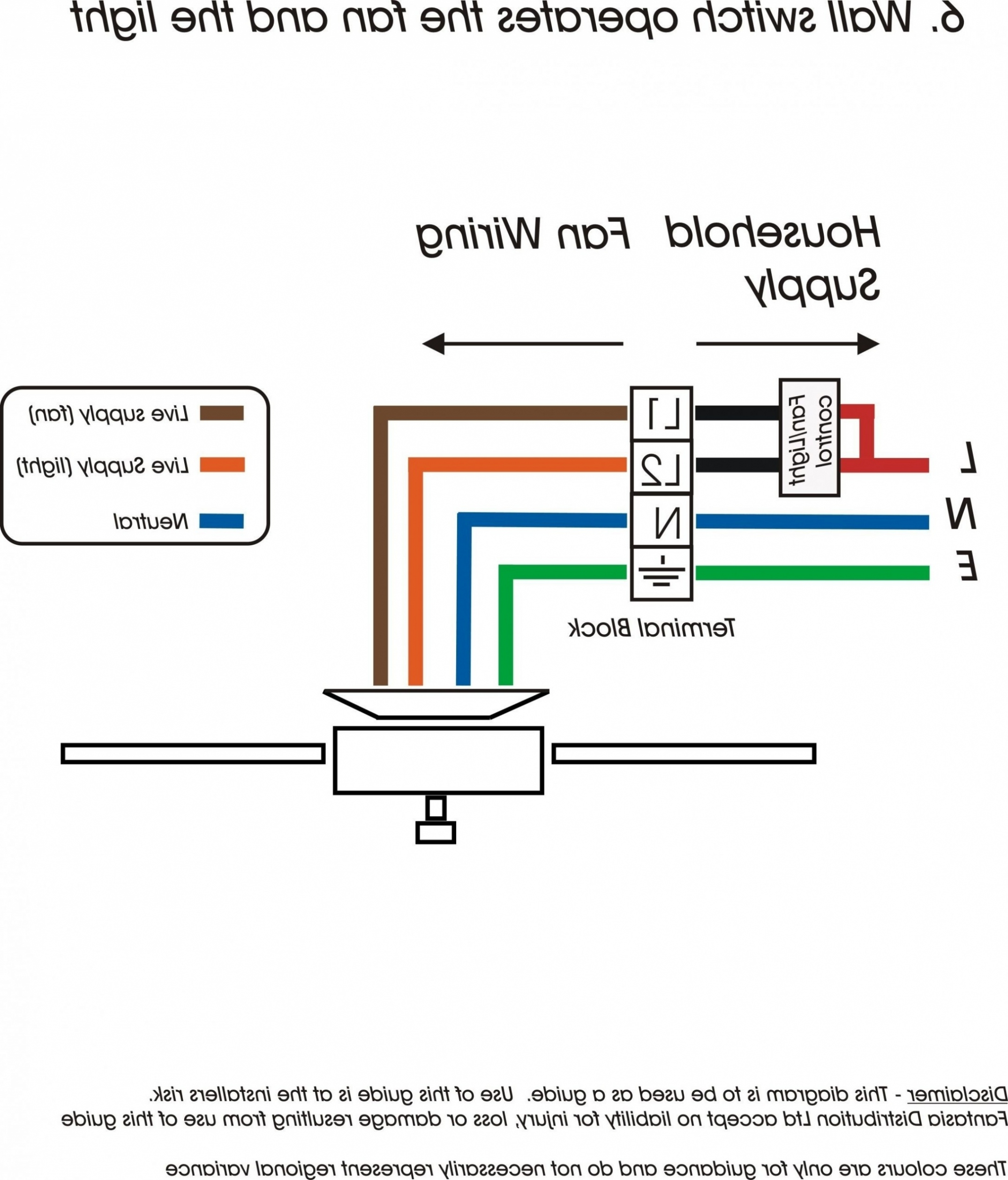
A wiring diagram is a streamlined standard pictorial representation of an electrical circuit. Honeywell 4 wire thermostat wiring diagram. You can download all the image about home and design for free. Disconnect blue wire from relay 1 terminal 6, cut, strip, and connect to field wire l3. Using edrawmax to create your own wiring diagram.

Figure c.1, network wiring diagram, updated. Honeywell 4 wire thermostat wiring diagram. Sensors will typically be wired to the engine ecm and the emcp 4 will get that information from the engine. You can download all the image about home and design for free. 2000 chevrolet silverado 1500 wiring diagram.
 Source: dentistmitcham.com
Design, the powerflex 4m ac drive is the smallest and most cost effective member. They can be used as a guide when wiring the controller. The next t stat the honeywell t8775c1005 2 non programmable t stat can control both heating and cooling as well as manual fan operation with just four wires. It conducts electricity from the engine to the alternator while the. You make the decisions when it comes to the technology in your home.
 Source: swageronline.com
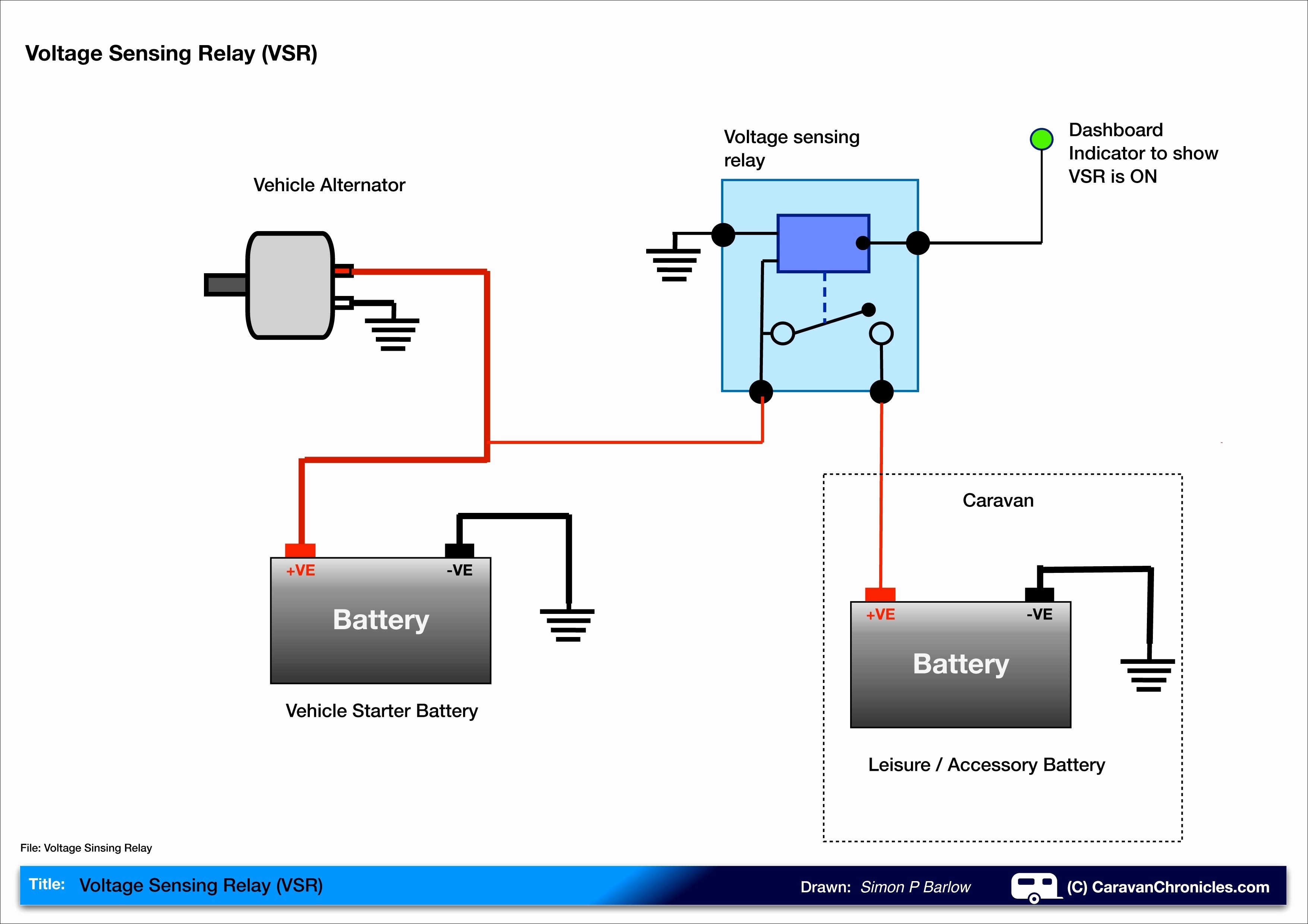
It conducts electricity from the engine to the alternator while the. 4 typical wiring diagrams for push button control stations pilot light selection pilot light selection is based on the following factors; Diy enthusiasts use wiring diagrams but they are also common in home building and auto repair. 13 abb vd4 wiring diagram. Online library wiring diagram engine control 4a fe wiring diagram engine control 4a fe when somebody should go to the ebook stores, search launch by shop, shelf by shelf, it is in reality problematic.
 Source: pinterest.com
Voltage, lamp requirements, environment, and cost.4 the voltage of a pilot light must match the voltage supply. When you employ your finger or perhaps the actual circuit along with your eyes, it is easy to mistrace the circuit. V primary, v secondary only. Emcp 4 2 wiring diagram ~ hello friends our site, this is images about emcp 4 2 wiring diagram posted by brenda botha in emcp category on nov 16, you can also find other images like wiring diagram, parts diagram, replacement parts, electrical diagram, repair manuals, engine diagram, engine scheme, wiring harness, fuse box, vacuum diagram, timing belt, timing. To make this circuit work, a 3 way dimmer can be used in place of one, or both of the standard 3 way switches.
 Source: stickerdeals.net
The ignition input wire is attached to the engine. Be advised that wiring the device while power is on may cause damage to the terminal. Paulmann�s led wire system airled appears to float in space and presents a brilliant display of light. If you are not using a metal control plate, you will need to run a small ground wire from the volume pot to the tone pot. Honeywell thermostat wiring diagram 4 wire source.
This site is an open community for users to do sharing their favorite wallpapers on the internet, all images or pictures in this website are for personal wallpaper use only, it is stricly prohibited to use this wallpaper for commercial purposes, if you are the author and find this image is shared without your permission, please kindly raise a DMCA report to Us.
If you find this site serviceableness, please support us by sharing this posts to your preference social media accounts like Facebook, Instagram and so on or you can also save this blog page with the title control 4 wiring diagram by using Ctrl + D for devices a laptop with a Windows operating system or Command + D for laptops with an Apple operating system. If you use a smartphone, you can also use the drawer menu of the browser you are using. Whether it’s a Windows, Mac, iOS or Android operating system, you will still be able to bookmark this website.
