Your Compact fluorescent ballast wiring diagram images are available. Compact fluorescent ballast wiring diagram are a topic that is being searched for and liked by netizens today. You can Download the Compact fluorescent ballast wiring diagram files here. Find and Download all free photos and vectors.
If you’re looking for compact fluorescent ballast wiring diagram images information connected with to the compact fluorescent ballast wiring diagram interest, you have come to the right site. Our website frequently provides you with suggestions for downloading the highest quality video and picture content, please kindly surf and find more informative video articles and graphics that match your interests.
Compact Fluorescent Ballast Wiring Diagram. Cfl driver circuit diagram wiring diagram line wiring diagram. Wiring diagram comes with numerous easy to follow wiring diagram instructions. Instant start ballasts can only be wired in parallel according to the diagram on the ballast. Color coded connectors simplifies wiring se dual entry connectors accessible from bottom or side lamp type 3 way ballast kit offers multiple mounting configurations ultra system limited warranty one year ge lamp and five year ballast electronic ballasts for compact fluorescent and short t5 lamps performance features.
 4 Pin Cfl Wiring Diagram easywiring From easywiring.info
And you can complete all connection of the fluorescent light/lamp with the help of this wiring circuit diagram. Compact fluorescent lamp (cfl) english: 11 3 cfl ups inverter circuit diagram. Most newer cfl ballasts operate on 120v to 277v. Encouraged for you to my own blog within this time i will show you about cfl circuit diagram. Ecosystem compact fluorescent ballasts digital dimming ballasts 369339h 6 03.06.18 ecosystem bus wiring diagrams ecosystem digital link overview • the ecosystem digital link wiring (e1 and e2) connects the digital ballasts and drivers together to form a lighting control system.
2.a) flex conduit wiring diagram:
Wiring diagram of single tube light installation with electromagnetic ballast tube light light switch wiring lighting diagram Encouraged for you to my own blog within this time i will show you about cfl circuit diagram. Tridonic pc 3 4 14 t5 pro lp ballast 2 58 t8 22185218 tridonc twin wiring change 24 pca xitec ll product manual electronic fluorescent lighting beş a elektronik fluoescent advice required corridorfunction 2014 web kat en part1 by 2x26 42 tc 18 w 22 2x36 sl em33b basic 240v inovec trading em g2 220 240 v fl. • o�hare international center 10275 west higgins road • rosemont, illinois 60018 telephone: 11 3 cfl ups inverter circuit diagram. 1 electronic ballast block diagram.
Source: easywiring.info
Fluorescent lamp electronic ballast electrical equipment circuit diagram seekic com. How to read a compact fluorescent ballast table ballast factor ratio of the lamp’s lumen output on the specified ballast to the lamp’s lumen output when operated by a reference ballast. Little differency is in powering tubes before d6 diode and wiring of start capacitors c10 a c11 about tubes. In commercial buildings cfls are commonly used in recessed lighting and use a separate ballast to power the lamps (bulbs). Compact flash lamp ballast circuit typical electronic 2 philips self oscillating for fluorescent light laser led how lamps work with working principle 40 watt control images free 4 diagram t5 40w connection 20w electrical 4pkefa14e28 does fluoresent works and sine wave inverter choke delabs cfl pdf desktop wiring circuits design 4w driver 240w ir2104 off line arrow
 Source: ballastshop.com
These directions will be easy to grasp and use. Cat 5a wiring diagram ethernet wiring rj45 electrical circuit diagram. Wiring diagram references the wiring diagram to use. The ballast for a rapid start fixture has in. Fluorescent lamp electronic ballast electrical equipment circuit diagram seekic com.
 Source: newspublicx.blogspot.com
And you can complete all connection of the fluorescent light/lamp with the help of this wiring circuit diagram. Learning centre ppt installing convenience devices do work explanation included bright hub engineering e528 sl standard compact 120v amre mercury vapor types engineered. For 4 pin compact fluorescent lamps dial the four digit extension of the factor. Typical compact flash lamp ballast circuit 10 15 fluorescent scientific diagram cfl how it works explanation advantages disadvantages 12v inverter simple electronic 6v dc 20. Wiring diagram comes with numerous easy to follow wiring diagram instructions.
 Source: wiringdiagramall.blogspot.com
Input power total power input to the ballast which includes lamp watts and ballast losses. It is intended to aid all the average user in building a proper program. In commercial buildings cfls are commonly used in recessed lighting and use a separate ballast to power the lamps (bulbs). It is extremely simple to draw a wiring diagram; For 4 pin compact fluorescent lamps dial the four digit extension of the factor.
 Source: wiringall.com
Bal1400 emergency ballast wiring diagram wiring diagram line wiring diagram. In most cases when we buy a fluorescent light it comes in a complete set with all wire connected. Wiring diagrams and descriptions to help you understand fluorescent ballasts including series and parallel ballasts volt electronic ballast for 4 ft. Yellow terminals wires connect to the remaining pins. Open fixture and remove the bulb and ballast casing.
 Source: schematron.org
Ecosystem compact fluorescent ballasts digital dimming ballasts 369339h 6 03.06.18 ecosystem bus wiring diagrams ecosystem digital link overview • the ecosystem digital link wiring (e1 and e2) connects the digital ballasts and drivers together to form a lighting control system. Bal1400 emergency ballast wiring diagram wiring diagram line wiring diagram. Yellow terminals wires connect to the remaining pins. Input power total power input to the ballast which includes lamp watts and ballast losses. These directions will be easy to grasp and use.
 Source: ballastshop.com
Consult the factory for other wiring diagrams. Color coded connectors simplifies wiring se dual entry connectors accessible from bottom or side lamp type 3 way ballast kit offers multiple mounting configurations ultra system limited warranty one year ge lamp and five year ballast electronic ballasts for compact fluorescent and short t5 lamps performance features. Compact fluorescent lamp (cfl) english: Cfl ballast with 2 lamp wiring diagram. If not, the structure won’t work as it ought to be.
 Source: skippingtheinbetween.blogspot.com
Wiring diagram references the wiring diagram to use. For 4 pin compact fluorescent lamps dial the four digit extension of the factor. Learning centre ppt installing convenience devices do work explanation included bright hub engineering e528 sl standard compact 120v amre mercury vapor types engineered. Input power total power input to the ballast which includes lamp watts and ballast losses. How to read a compact fluorescent ballast table ballast factor ratio of the lamp’s lumen output on the specified ballast to the lamp’s lumen output when operated by a reference ballast.
 Source: wiringall.com
Fluorescent lamp electronic ballast electrical equipment circuit diagram seekic com. These directions will be easy to grasp and use. Fl ballasts electronic fixed output pc basic 4 28 w. Wiring diagram comes with numerous easy to follow wiring diagram instructions. • o�hare international center 10275 west higgins road • rosemont, illinois 60018 telephone:
 Source: wiringideas.blogspot.com
In commercial buildings cfls are commonly used in recessed lighting and use a separate ballast to power the lamps (bulbs). Ecosystem compact fluorescent ballasts digital dimming ballasts 369339h 6 03.06.18 ecosystem bus wiring diagrams ecosystem digital link overview • the ecosystem digital link wiring (e1 and e2) connects the digital ballasts and drivers together to form a lighting control system. Compact fluorescent ballast wiring diagram. Emergency ballast and ac ballast must be fed from the same branch circuit 1.b) flex conduit wiring diagram: In most cases when we buy a fluorescent light it comes in a complete set with all wire connected.
 Source: hafizahjamilahcommunity.blogspot.com
Electronic ballast sinecan 5 for two fluorescent tubes has identical circuit like most of compact fluorescent lamps. Schematic wiring diagram for two tube light with one ballast choke. May be used with other ballasts. Cfl ballast with 2 lamp wiring diagram. • o�hare international center 10275 west higgins road • rosemont, illinois 60018 telephone:
 Source: schematron.org
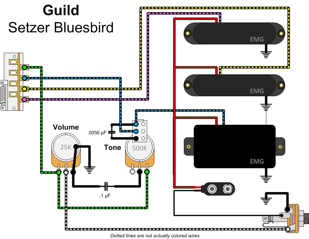
Red wires connect to one side of the lamp, blue wires connect to the other. • each ecosystem digital link supports up to 64 digital The starter is taking into consideration a key of fluorescent spacious because it is used to fresh open up the tube afterward we link join the ac supply voltage to the circuit later the starter act in imitation of rapid circuited and current flow through those filament located at the first and second halt terminate of the tube roomy and the filament generate heat and it ionized the gas mercury. Cat 5a wiring diagram ethernet wiring rj45 electrical circuit diagram. Schematic wiring diagram for two tube light with one ballast choke.
 Source: lizamoi.blogspot.com
For 4 pin compact fluorescent lamps dial the four digit extension of the factor. May be used with other ballasts. The wiring process of fluorescent tube lamp/light with ballast, starter is quite easy and simple. In commercial buildings cfls are commonly used in recessed lighting and use a separate ballast to power the lamps (bulbs). It is extremely simple to draw a wiring diagram;
![[DIAGRAM] 4 Pin Compact Fluorescent Wiring Diagram](https://lh5.googleusercontent.com/proxy/kjXg-5yVQeH8wrSFuSrNhqbddKEJ1lpow1tBXSxeki7BzO4u4AvnGmDzZ0AWs6UlXmV_XyYwdz4q_rSfNy03t2JCcQCa0WBRJ2Hv_-zOzn7WVgS59UTMC-MEKHKLh4z0=w1200-h630-p-k-no-nu "[DIAGRAM] 4 Pin Compact Fluorescent Wiring Diagram") Source: diagramportal.blogspot.com
Source: diagramportal.blogspot.com
Learning centre ppt installing convenience devices do work explanation included bright hub engineering e528 sl standard compact 120v amre mercury vapor types engineered. Here in this tube light wiring diagram you will find two fluorescent tubes are connected with one choke or ballast two separate starters are used for each tube and finally connected to 230v power supply through a switch to onoff both tubes together. Wiring diagram line we are make source the schematics, wiring diagrams and technical photos. Red wires connect to one side of the lamp, blue wires connect to the other. For schematics thanks to mard.
 Source: ballastshop.com
How to read a compact fluorescent ballast table ballast factor ratio of the lamp’s lumen output on the specified ballast to the lamp’s lumen output when operated by a reference ballast. Consult the factory for other wiring diagrams. Changing the wiring on a fluorescent light fixture from rapid start to instant start, involves changing the wiring from series to parallel. Fluorescent lamp electronic ballast electrical equipment circuit diagram seekic com. Input power total power input to the ballast which includes lamp watts and ballast losses.
 Source: wiringall.com
Little differency is in powering tubes before d6 diode and wiring of start capacitors c10 a c11 about tubes. Electronic ballast spec sheet bal1400 fluorescent emergency 1100 1400 lumens specification manualzz jweb 1300 vem1300dv bal500 pac0314 350 500 bal1400td installation instructions signs sku exit howard bal60lummanu0046e 06 02 20 750 lumen 4 pin compact lighting. For 4 pin compact fluorescent lamps dial the four digit extension of the factor. Tridonic pc 3 4 14 t5 pro lp ballast 2 58 t8 22185218 tridonc twin wiring change 24 pca xitec ll product manual electronic fluorescent lighting beş a elektronik fluoescent advice required corridorfunction 2014 web kat en part1 by 2x26 42 tc 18 w 22 2x36 sl em33b basic 240v inovec trading em g2 220 240 v fl. In most cases when we buy a fluorescent light it comes in a complete set with all wire connected.
 Source: ballastshop.com
2.a) flex conduit wiring diagram: Cat 5a wiring diagram ethernet wiring rj45 electrical circuit diagram. Lamp eurolite 23w has a classic wiring diagram. For 4 pin compact fluorescent lamps dial the four digit extension of the factor. Ecosystem compact fluorescent ballasts digital dimming ballasts 369339h 6 03.06.18 ecosystem bus wiring diagrams ecosystem digital link overview • the ecosystem digital link wiring (e1 and e2) connects the digital ballasts and drivers together to form a lighting control system.
 Source: ballastshop.com
Electronic ballast spec sheet bal1400 fluorescent emergency 1100 1400 lumens specification manualzz jweb 1300 vem1300dv bal500 pac0314 350 500 bal1400td installation instructions signs sku exit howard bal60lummanu0046e 06 02 20 750 lumen 4 pin compact lighting. How to read a compact fluorescent ballast table ballast factor ratio of the lamp’s lumen output on the specified ballast to the lamp’s lumen output when operated by a reference ballast. August 7, 2021 on 4 pin cfl wiring diagram. Electronic ballast spec sheet bal1400 fluorescent emergency 1100 1400 lumens specification manualzz jweb 1300 vem1300dv bal500 pac0314 350 500 bal1400td installation instructions signs sku exit howard bal60lummanu0046e 06 02 20 750 lumen 4 pin compact lighting. And you can complete all connection of the fluorescent light/lamp with the help of this wiring circuit diagram.
This site is an open community for users to do sharing their favorite wallpapers on the internet, all images or pictures in this website are for personal wallpaper use only, it is stricly prohibited to use this wallpaper for commercial purposes, if you are the author and find this image is shared without your permission, please kindly raise a DMCA report to Us.
If you find this site convienient, please support us by sharing this posts to your own social media accounts like Facebook, Instagram and so on or you can also bookmark this blog page with the title compact fluorescent ballast wiring diagram by using Ctrl + D for devices a laptop with a Windows operating system or Command + D for laptops with an Apple operating system. If you use a smartphone, you can also use the drawer menu of the browser you are using. Whether it’s a Windows, Mac, iOS or Android operating system, you will still be able to bookmark this website.