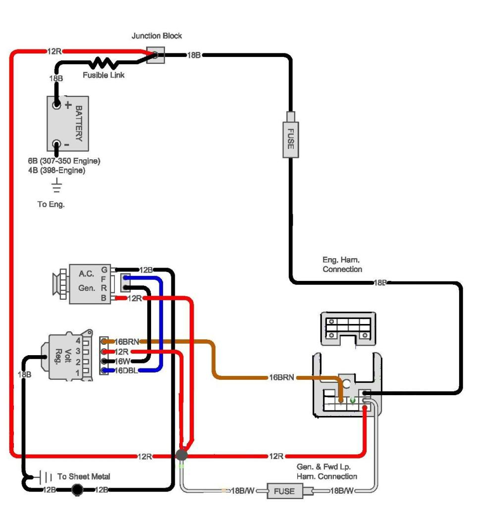
Your Combined brake and turn signal wiring diagram images are available in this site. Combined brake and turn signal wiring diagram are a topic that is being searched for and liked by netizens now. You can Get the Combined brake and turn signal wiring diagram files here. Get all free photos.
If you’re searching for combined brake and turn signal wiring diagram pictures information related to the combined brake and turn signal wiring diagram keyword, you have visit the right blog. Our website frequently provides you with suggestions for seeking the maximum quality video and picture content, please kindly surf and locate more enlightening video articles and graphics that fit your interests.
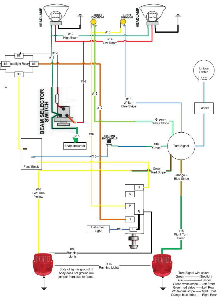
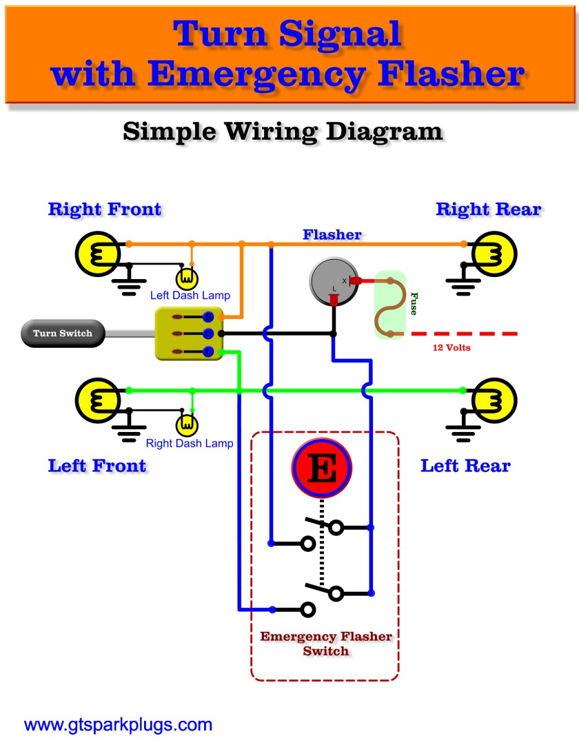
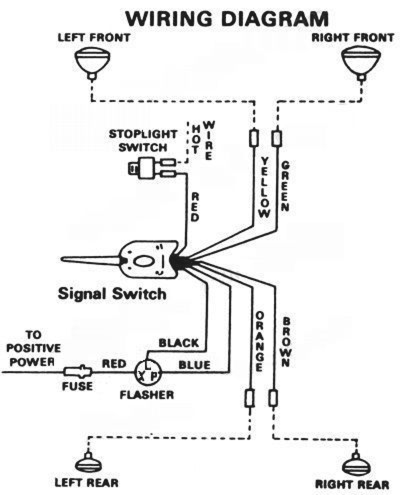
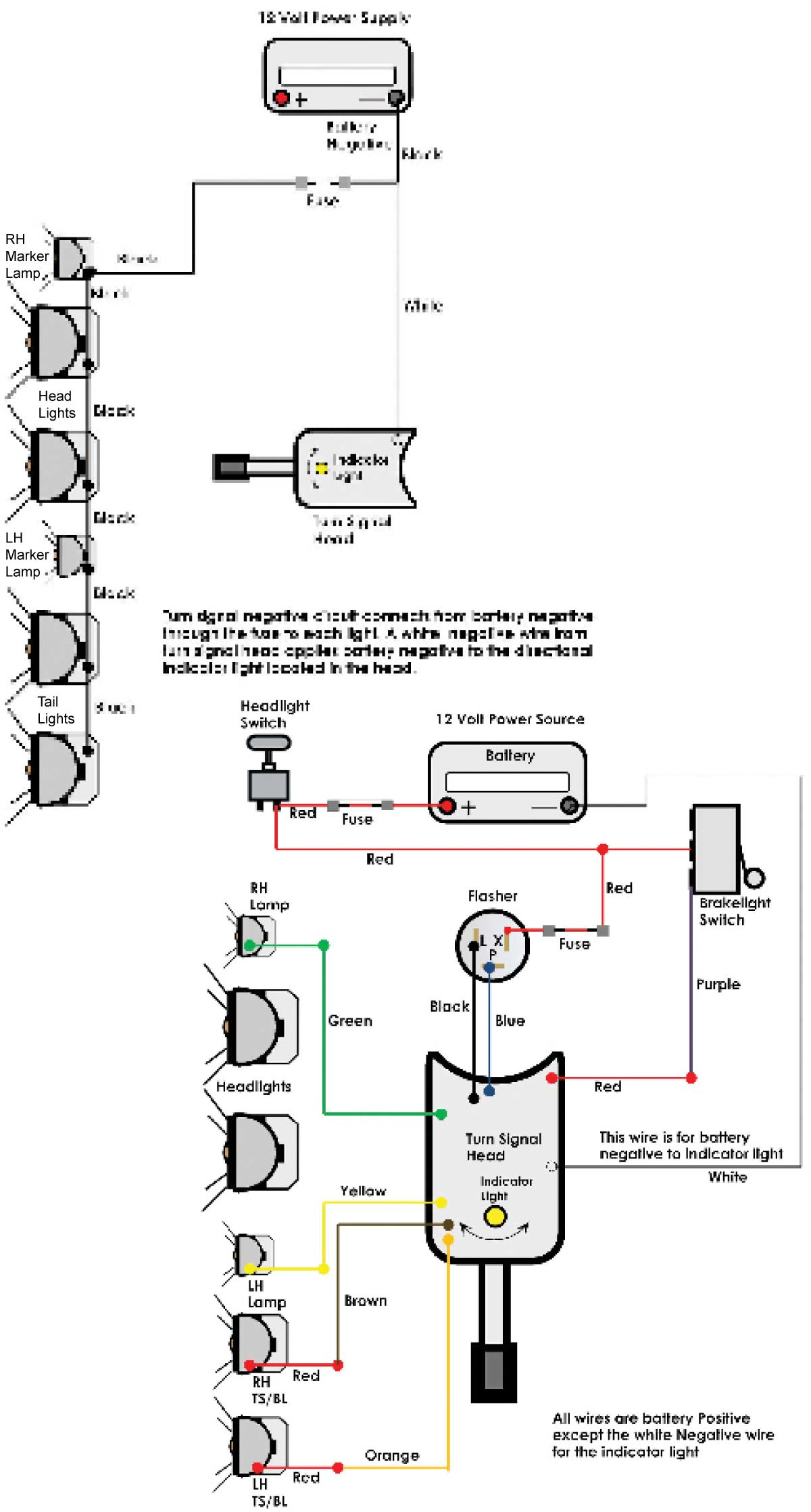
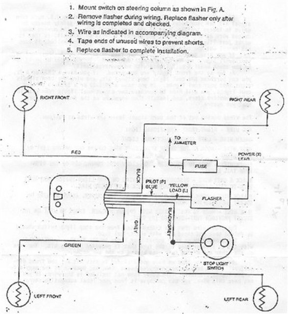
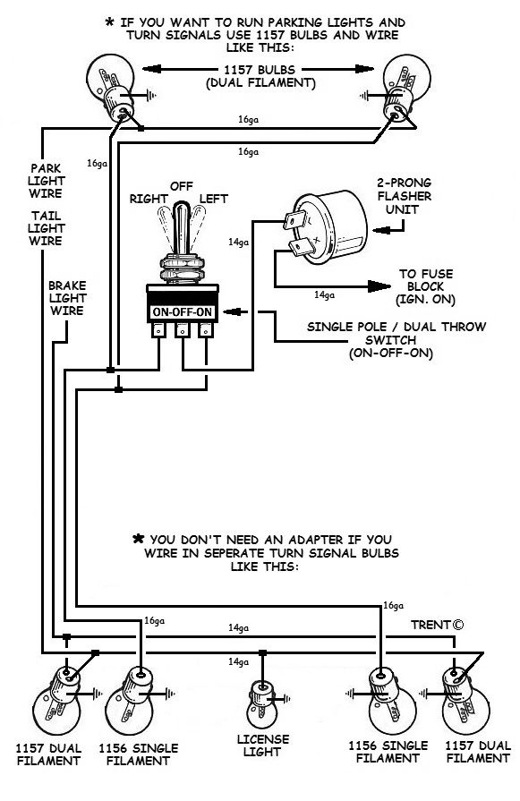
Combined Brake And Turn Signal Wiring Diagram. It is very simple to use your three wire signal switch to control four (5) pin bosch type relays and achieve what you want. Warnings and cautions attach the diodes as close to the towed vehicle�s lights as possible, to avoid interaction with other Then wire another 1n4001 diode in series with the brake light 12v source. They will combine the brake wiring and.
 7 Best Harley tail light turn signal combination From keyenergypark.com
Typically the ordinary pliers would give you a loose connection that may cause trouble in future. Hard wire only vehicle has combined brake and turn signals brake light wire on harness is not grounded. Thats why there are numerous. Od was operative only in top up to ts6266, may, 1955. This specific is the optimum level of electrical existing they can safely bring. If the two wires are manually combined in an attempt to mimic the combined option listed above they will create a cross circuit and the lights will come on when they shouldn t.
The converter will need to be installed after the the connector on the trailer side.
Combined brake and turn signal wiring diagram jumat, 19 november 2021 edit brake switch g gp gp gp gp reverse lights switch gn g gn gn g w fuel pump w lgn lgn lgp lgp lgp g gr gr lgu rh ts green indicator lgy lh ts indicator gw green gw ts switch l turn signal flasher b cigar lighter fuel level speedometer tachometer oil pressurewater. A circuit is generally composed by several components. What you need is a converter to take the separate turn and brake light circuits and combine them. One brake light fitted up to ts15601, may, 1957, for us market. Then wire another 1n4001 diode in series with the brake light 12v source. Each component ought to be set and connected with different parts in specific way.
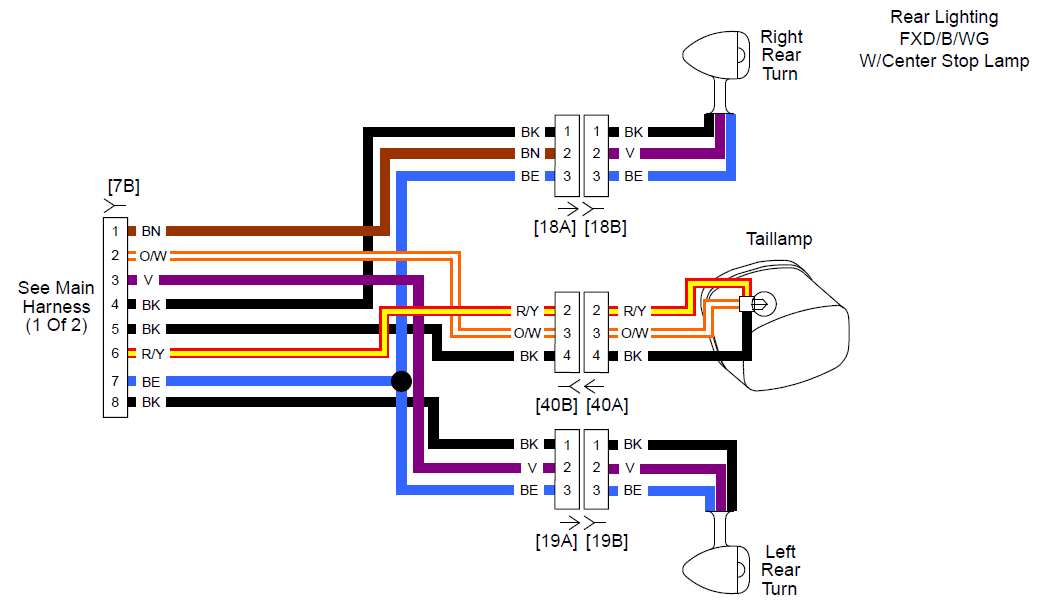 Source: hdforums.com
What you need is a converter to take the separate turn and brake light circuits and combine them. With a circuit tester identify the brake light taillight and turn signal wiring. Each component ought to be set and connected with different parts in specific way. What this gives you is 6v for tailight operation, 12v for brake and turn signal operation. L turn/brake , r turn/brake, tail lights, ground.
 Source: ford-trucks.com
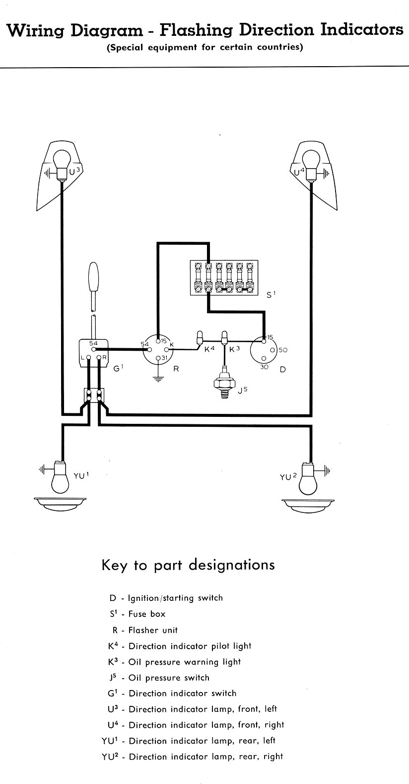
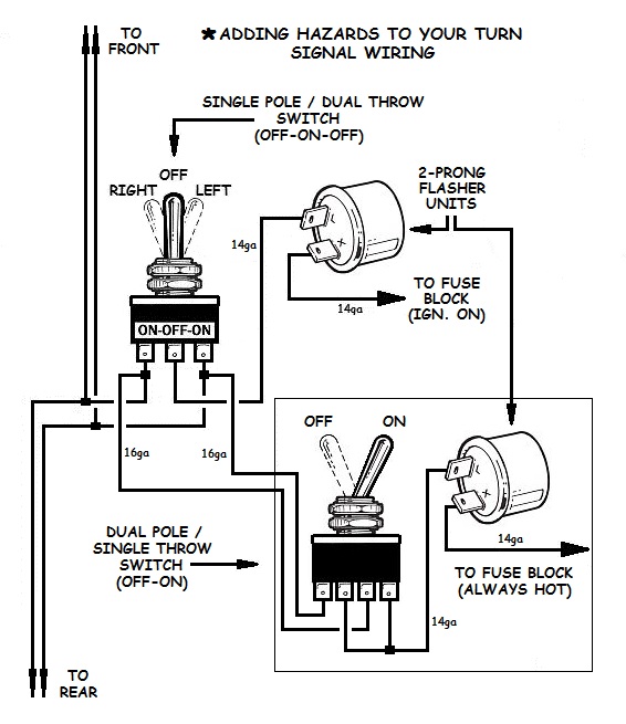
A quick and cheap way that works just as good is a tail light wiring converter for trailers. It is very simple to use your three wire signal switch to control four (5) pin bosch type relays and achieve what you want. Combined brake and turn signal wiring diagram jumat, 19 november 2021 edit brake switch g gp gp gp gp reverse lights switch gn g gn gn g w fuel pump w lgn lgn lgp lgp lgp g gr gr lgu rh ts green indicator lgy lh ts indicator gw green gw ts switch l turn signal flasher b cigar lighter fuel level speedometer tachometer oil pressurewater. A wiring diagram is a streamlined standard pictorial depiction of an electric circuit. There are two types — combined or separate.
 Source: dentistmitcham.com
Combined brake and turn signal wiring diagram. September 10, 2021 on chevy stop/turn/tail light wiring diagram. Combined brake and turn signal wiring diagram. A diode is just a gate. Brake turn signal wiring diagram wiring diagram.
 Source: annawiringdiagram.com
Od was operative only in top up to ts6266, may, 1955. How do you combine brake and turn signal lights? Curt makes a module designed to separate the circuits for trailer lighting. The rest you can ignore. This diagram was designed for 12 volt systems, but can also be used for 6 volt systems.
 Source: thenabnab.blogspot.com
This will take the signal from the vehicle that has the turn signal. If you have a single wire coming out of your rear turn signal fixtures there are. The vehicle will be wired for towing according to the type of brake and turn signals in both vehicles. What this gives you is 6v for tailight operation, 12v for brake and turn signal operation. They will combine the brake wiring and.

This diagram was designed for 12 volt systems, but can also be used for 6 volt systems. The vehicle will be wired for towing according to the type of brake and turn signals in both vehicles. 1 trick that we 2 to printing a similar wiring plan off twice. What this gives you is 6v for tailight operation, 12v for brake and turn signal operation. The converter will need to be installed after the the connector on the trailer side.
![[DIAGRAM] Trailer Running Lights But No Brake Lights Or [DIAGRAM] Trailer Running Lights But No Brake Lights Or](http://airlinebrats.com/rc51/ledlighting/FrontEnd_LED_wiring.jpg) Source: diagramsgumbs.mammeinazione.it
Source: diagramsgumbs.mammeinazione.it
Check the switch’s wiring diagram and find the single wire that establishes a connection between the brake light and turn signal switches. A quick and cheap way that works just as good is a tail light wiring converter for trailers. One brake light fitted up to ts15601, may, 1957, for us market. September 10, 2021 on chevy stop/turn/tail light wiring diagram. A wiring diagram is a streamlined.
 Source: 2020cadillac.com
By vallery masson on september 10, 2021. 2 wire stop/turn/tail light wiring diagram. Wiring brake and turn signals diagram. Typically the ordinary pliers would give you a loose connection that may cause trouble in future. The driver’s side is normally yellow and carries the left turn signal and brake.
 Source: 2020cadillac.com
It is very simple to use your three wire signal switch to control four (5) pin bosch type relays and achieve what you want. Wiring diagram for 1997 chevy silverado tail lights. This will take the signal from the vehicle that has the turn signal. If you have a single wire coming out of your rear turn signal fixtures there are. Combined brake and turn signal wiring diagram.
 Source: jalopyjournal.com
The rest you can ignore. See diagram b2 for later wiring diagram. Which wire is the brake light? On the output side you will have the yellow wire for left turn signal only, green for right turn signal. In a combined system (figure 1), the brake light flashes for the turn signal;
 Source: keyenergypark.com
Then wire both sources (after the diodes) to the bulbs. This will take the signal from the vehicle that has the turn signal. Runs your wires into the converter and coming out of the converter will be four wires. Then wire another 1n4001 diode in series with the brake light 12v source. Dozens of stop turn tail light wiring diagram html wiring diagram examples let you be instantly productive.
 Source: easywiring.info
4 wire tail light wiring diagram wiring diagram is a simplified up to standard pictorial representation of an electrical circuit. There are two types — combined or separate. This will take the signal from the vehicle that has the turn signal. By vallery masson on september 10, 2021. Combined brake and turn signal wiring diagram source:
 Source: orpingtonengraving.com
Combined turn signal and horn switch turn signal flasher turn signal indicator lh front lh rear rh front b l gn gn gn gr gr gw gw gw gw gr b b. The white input wire is ground (earth), yellow is combined left turn signal and brake light, and green is combined right turn and brake light. Some have the tail light wire running through them (4 wire into 3 wire), and some don�t (3 wire into 2 wire). A diode is just a gate. A diode is just a gate.
 Source: how-to-build-hotrods.com
How do you combine brake and turn signal lights? Dozens of stop turn tail light wiring diagram html wiring diagram examples let you be instantly productive. If not, the arrangement won’t work as. They both do the same thing. Wiring brake and turn signals diagram.
 Source: 2020cadillac.com
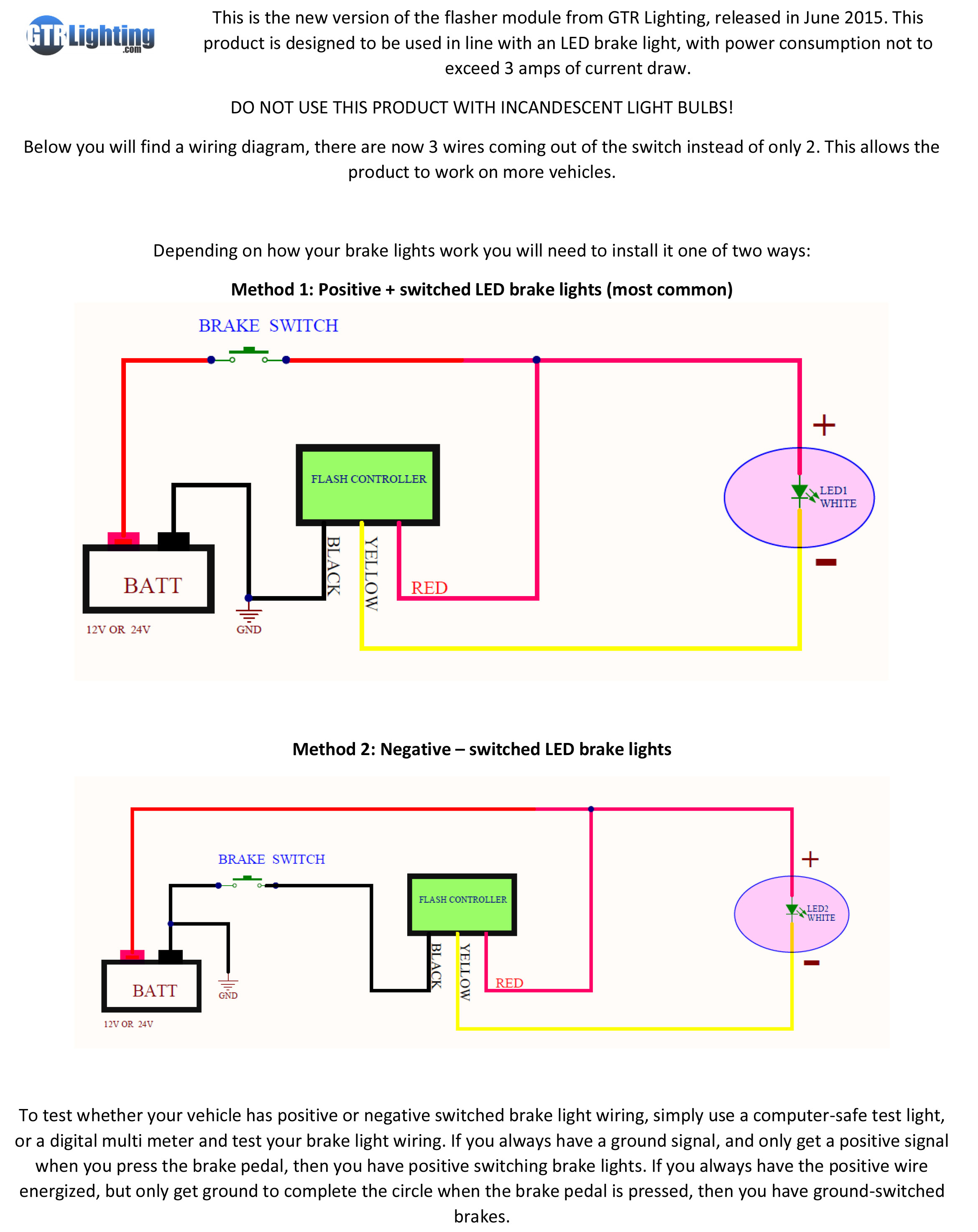
Combined brake and turn signal wiring diagram source: On the output side you will have the yellow wire for left turn signal only, green for right turn signal. Runs your wires into the converter and coming out of the converter will be four wires. Wiring diagram for 1997 chevy silverado tail lights. Stated use for it is when the toe vehicle has seperate outputs to the turn brake bulbs and the trailer has only one light each side with a single bulb.
 Source: jalopyjournal.com
Brake turn signal wiring diagram wiring diagram. If the two wires are manually combined in an attempt to mimic the combined option listed above they will create a cross circuit and the lights will come on when they shouldn t. A diode is just a gate. One brake light fitted up to ts15601, may, 1957, for us market. Combined brake and turn signal wiring diagram.
 Source: annawiringdiagram.com
Wiring brake and turn signals diagram. They both do the same thing. This specific is the optimum level of electrical existing they can safely bring. If you have a single wire coming out of your rear turn signal fixtures there are. This diagram was designed for 12 volt systems, but can also be used for 6 volt systems.
 Source: how-to-build-hotrods.com
Runs your wires into the converter and coming out of the converter will be four wires. See diagram b2 for later wiring diagram. If the two wires are manually combined in an attempt to mimic the combined option listed above they will create a cross circuit and the lights will come on when they shouldn t. A wiring diagram is a streamlined standard pictorial depiction of an electric circuit. September 10, 2021 on chevy stop/turn/tail light wiring diagram.
This site is an open community for users to do submittion their favorite wallpapers on the internet, all images or pictures in this website are for personal wallpaper use only, it is stricly prohibited to use this wallpaper for commercial purposes, if you are the author and find this image is shared without your permission, please kindly raise a DMCA report to Us.
If you find this site beneficial, please support us by sharing this posts to your favorite social media accounts like Facebook, Instagram and so on or you can also bookmark this blog page with the title combined brake and turn signal wiring diagram by using Ctrl + D for devices a laptop with a Windows operating system or Command + D for laptops with an Apple operating system. If you use a smartphone, you can also use the drawer menu of the browser you are using. Whether it’s a Windows, Mac, iOS or Android operating system, you will still be able to bookmark this website.
