Your Combination gas valve wiring diagram images are ready. Combination gas valve wiring diagram are a topic that is being searched for and liked by netizens now. You can Get the Combination gas valve wiring diagram files here. Get all royalty-free images.
If you’re searching for combination gas valve wiring diagram images information linked to the combination gas valve wiring diagram interest, you have come to the right blog. Our site frequently gives you hints for downloading the maximum quality video and picture content, please kindly surf and find more enlightening video content and images that fit your interests.
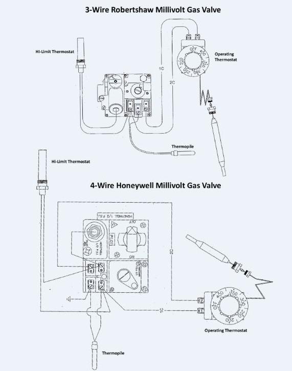
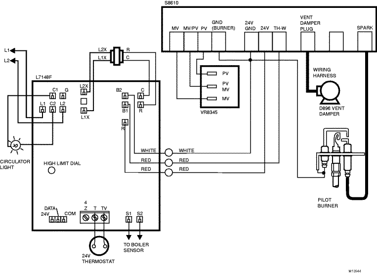
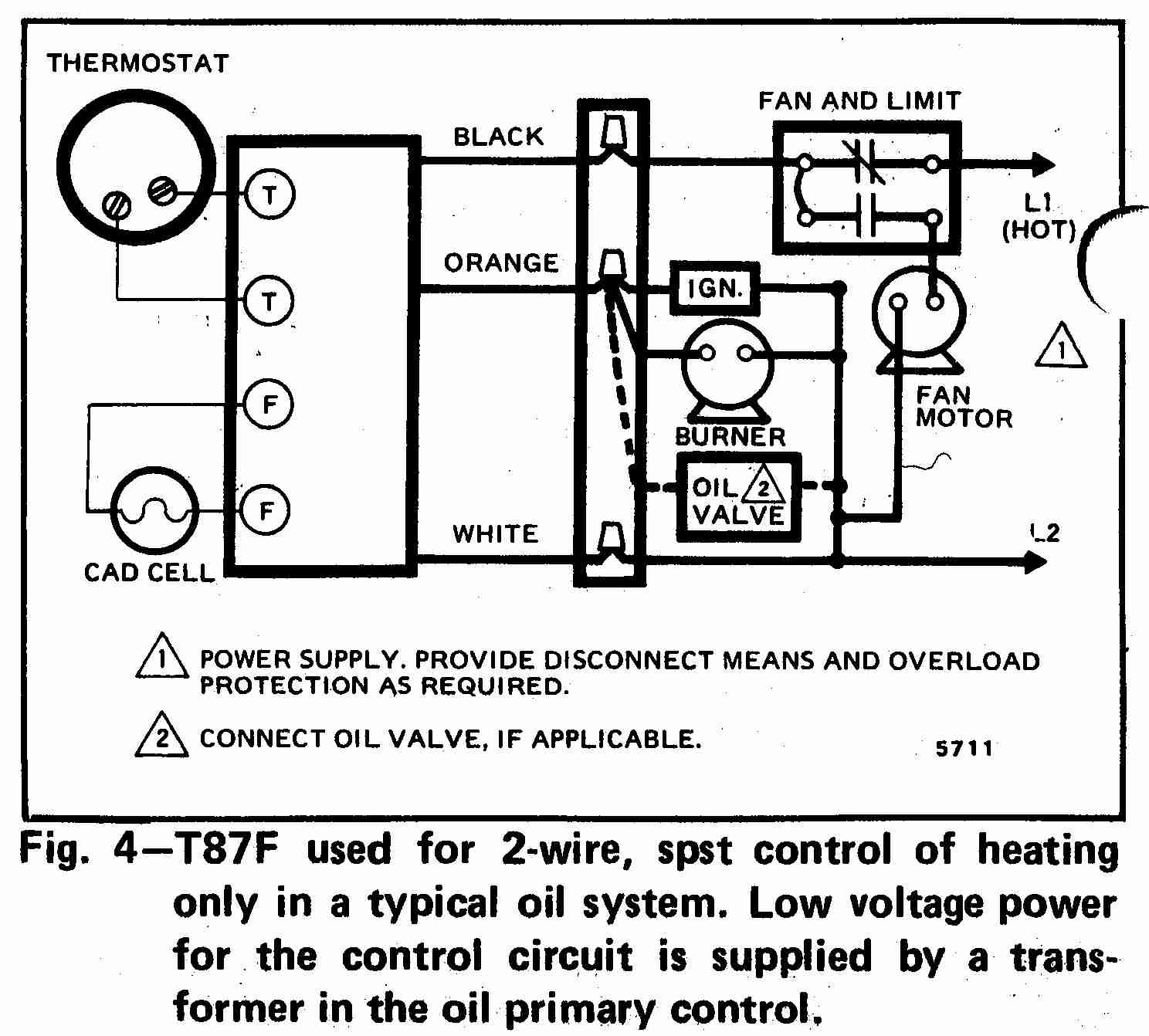
Combination Gas Valve Wiring Diagram. Mounting positions pipe sizes/capacities pipe size (inches) capacity (btu/hr) at 1 pressure drop across valve 1/ 2 x 3/8 1/ 2 x 1/2 1/ 2 x 3/4 3/ 4 x 3/4 100,000 230,000 230,000 If the existing wire terminals do not fit the terminals on the replacement gas valve, cut them off and replace them with the terminals provided in this kit. Before you search for a. The complete line of 700 500 millivolt gas valves offers a wide range of replacements from small capacity 3 8 pipe to high capacity 1.
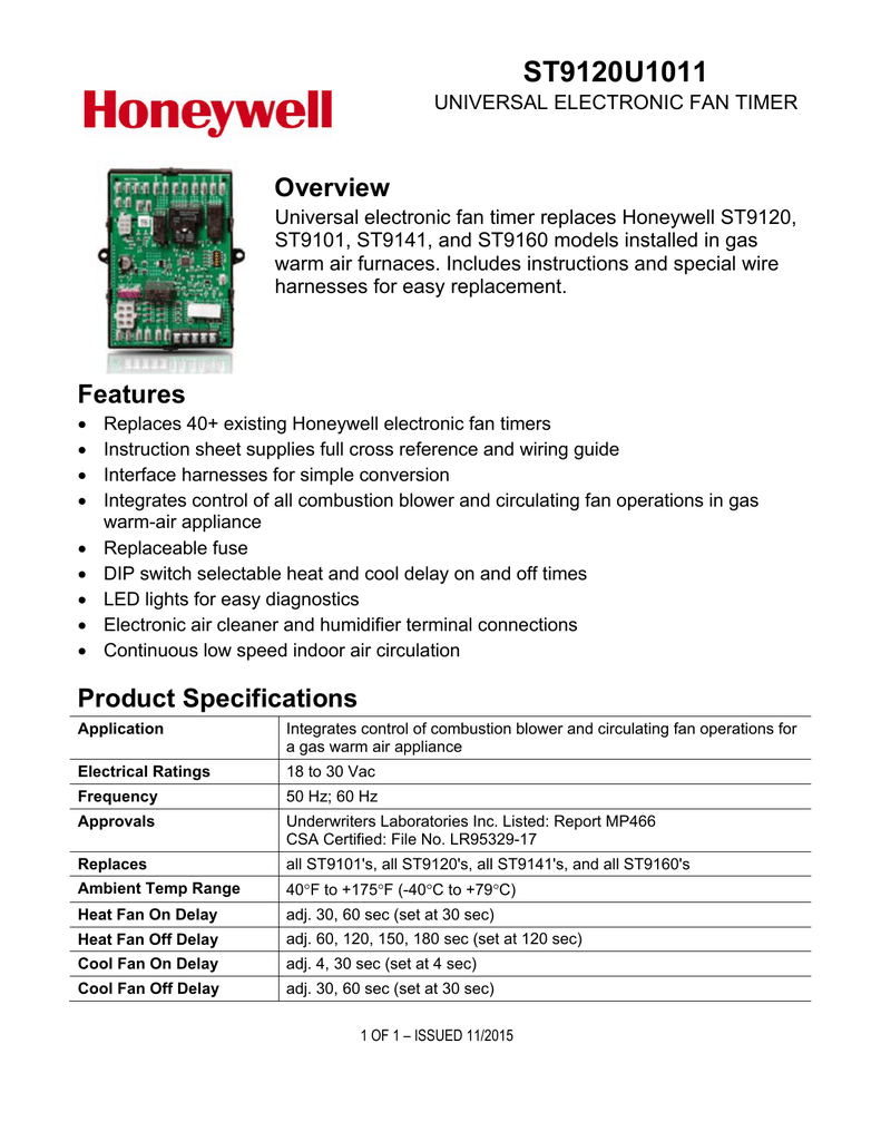 Honeywell Vr8200 Gas Valve Wiring Diagram From schematron.org
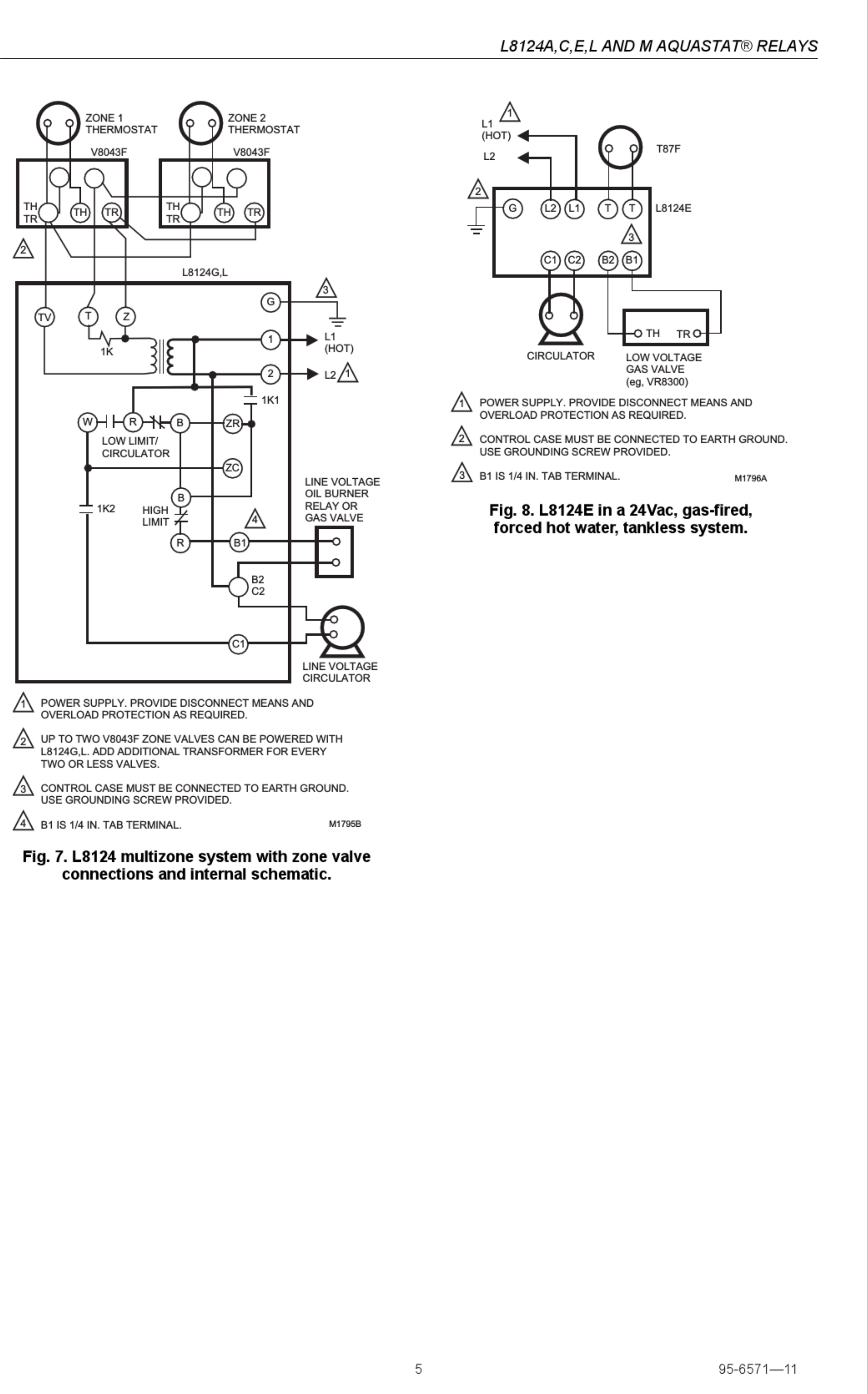
Electrician hq taco hydronic systems 3 sweat supplyhouse v8043 home v8043c d f g motorized where i find v4043 motorised combination 2 zones volt free switching s plan central esp diagrams way parts catalog manualzz thermostat geek wisdom faults v8044a1044 brass. Combination gas valve wiring diagram : Wiring per the wiring diagram below. Wiring diagrams for two zone valves with a combination boiler. If the existing wire terminals do not fit the terminals on the replacement gas valve, cut them off and replace them with the terminals provided in this kit. The automatic pilot safety is separa te from gas cock and provides shutoff in case of pilot outage.
Wiring diagrams for two zone valves with a combination boiler.
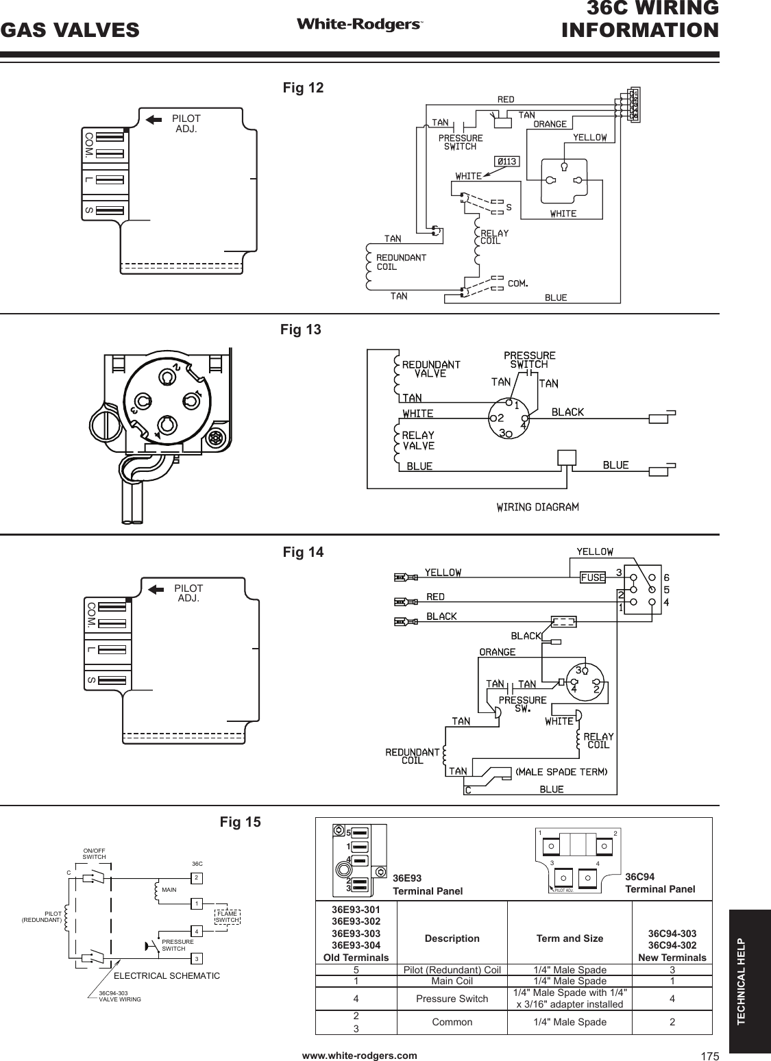
Honeywell gas valve wiring diagram. The 36h series combination gas valve is designed with redundant and main solenoid valves that control gas flow to the main burners, a pressure regulator to maintain a constant outlet pressure, and a two position on/off switch for electrical shutoff. Mounting positions pipe sizes/capacities pipe size (inches) capacity (btu/hr) at 1 pressure drop across valve 1/ 2 x 3/8 1/ 2 x 1/2 1/ 2 x 3/4 3/ 4 x 3/4 100,000 230,000 230,000 Millivolt, g 8ushing thermocouple block open kit: The complete line of 700 500 millivolt gas valves offers a wide range of replacements from small capacity 3 8 pipe to high capacity 1. Valve has 1 2 side outlets.
 Source: wiringdiagram.2bitboer.com
These simple visual representations all. Wiring per the wiring diagram below. Hz, 3.9 va anticipator setting: Electrician hq taco hydronic systems 3 sweat supplyhouse v8043 home v8043c d f g motorized where i find v4043 motorised combination 2 zones volt free switching s plan central esp diagrams way parts catalog manualzz thermostat geek wisdom faults v8044a1044 brass. Mounting positions pipe sizes/capacities pipe size (inches) capacity (btu/hr) at 1 pressure drop across valve 1/ 2 x 3/8 1/ 2 x 1/2 1/ 2 x 3/4 3/ 4 x 3/4 100,000 230,000 230,000
Source: old-school-new-body–review.blogspot.com
Wiring per the wiring diagram below. Honeywell gas valve wiring diagram. Standing/continuous pilot combination gas valve. I discuss the flow of gas through the valve sole. Millivolt, g 8ushing thermocouple block open kit:
 Source: schematron.org
Mantel clearance top view of fireplace bottom louver gas control valve. This video covers the wiring and electrical operation of an s plan system with two 2 port valves. Mantel clearance top view of fireplace bottom louver gas control valve. Learn how to shut off the valve controlling natural gas or liquid. Its only purpose in life is to connect the r terminal on the thermostat to the 24vac terminal on the.
 Source: wiringdiagram.2bitboer.com
Zone valve wiring manuals installation instructions guide to heating system valves inspection repair 3 zone heating control pack eph controls open and sealed system where the oil boiler a solid fuel stove two central heating zones domestic hot water dhw cylinder nrg awareness I discuss the flow of gas through the valve sole. The complete line of 700 500 millivolt gas valves offers a wide range of replacements from small capacity 3 8 pipe to high capacity 1. Th tr thermostat transformer terminal is the 24vac from the transformer. Robertshaw gas valve wiring help.
 Source: dragan103.blogspot.com
Upgraded replacement for honeywell furnace gas valve vra. Wiring diagrams for two zone valves with a combination boiler. The pain in reality is that every car is different. Reconnect the fryer to the gas and electrical power supplies. They include safety shutoff, a manual valve, two automatic operators, a pressure regulator, a pilot adjustment, and a conduit cover (vr4200 only).
 Source: atkinsjewelry.blogspot.com
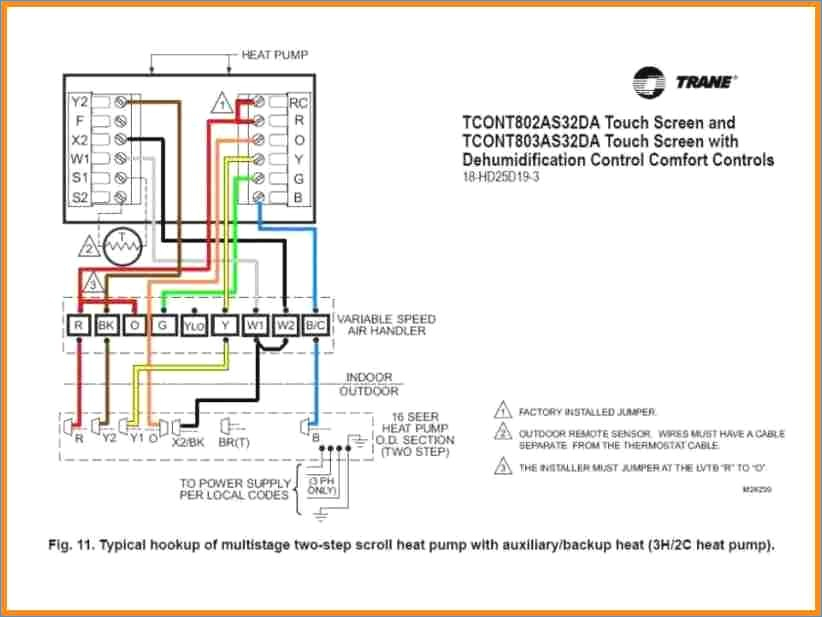
Th tr thermostat transformer terminal is the 24vac from the transformer. Combination gas valve wiring diagram : Honeywell vs820 user s manual manualzz 4 wiring diagrams 5 recommended spare th and tr on a gas valve terminal sv9501m8129 u vr800 icg furnace heater users millivolt fryer hot water boiler piping zone valves vr8345 universal electronic ignition terminals. Mantel clearance top view of fireplace bottom louver gas control valve. Th tr thermostat transformer terminal is the 24vac from the transformer.
 Source: infraredradiant.com
Th tr thermostat transformer terminal is the 24vac from the transformer. Control shown may not be identical to replacement control. The complete line of 700 500 millivolt gas valves offers a wide range of replacements from small capacity 3 8 pipe to high capacity 1. Model numbers below include features as described: Its only purpose in life is to connect the r terminal on the thermostat to the 24vac terminal on the.
 Source: kovodym.blogspot.com
Millivolt, g 8ushing thermocouple block open kit: Disconnect the pilot gas tube from the valve 4. Refer to the wiring diagram and pictures on the next page. Let�s look at what each of these terminals means: Mantel clearance top view of fireplace bottom louver gas control valve.
 Source: ricardolevinsmorales.com
The difference is that the zone valve switch is used to connect two terminals in the boiler together, rather than connecting 230v to. Mantel clearance top view of fireplace bottom louver gas control valve. Learn how to shut off the valve controlling natural gas or liquid. The way it works is: The 36h series combination gas valve is designed with redundant and main solenoid valves that control gas flow to the main burners, a pressure regulator to maintain a constant outlet pressure, and a two position on/off switch for electrical shutoff.
 Source: diagramweb.net
The gas valve part number is and is #15 (bottom right) in the exploded diagram if needed. These diagrams should be read in conjunction with product installation instructions. Before you search for a. Its only purpose in life is to connect the r terminal on the thermostat to the 24vac terminal on the. Check the tightness of all wiring connections, make sure the oven door is closing properly (if open, the bake ignition circuit will shut down after 60 seconds).
 Source: ricardolevinsmorales.com
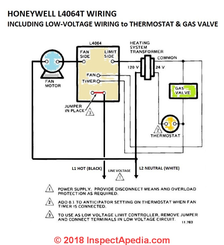
Tim smith from hudson valley community college discusses specific concepts found on a gas furnace wiring diagram. Honeywell gas valve wiring diagram. Crimp and solder the new terminals on the wires. Mantel clearance top view of fireplace bottom louver gas control valve. Combination gas valve inlet boss upright up or down left or right upright, 90° from upright or vertical note:
Source: diagramhelper.blogspot.com
Honeywell 4 wire zone valve wiring diagram wiring diagram line wiring diagram. The complete line of 700 500 millivolt gas valves offers a wide range of replacements from small capacity 3 8 pipe to high capacity 1. Standing/continuous pilot combination gas valve. If the existing wire terminals do not fit the terminals on the replacement gas valve, cut them off and replace them with the terminals provided in this kit. This video covers the wiring and electrical operation of an s plan system with two 2 port valves.
 Source: justanswer.com
Underfloor heating wiring diagram combi have a graphic associated with the otherunderfloor heating wiring diagram combi in addition it will include a picture of a kind that could be seen in the gallery of underfloor heating wiring diagram combi. These diagrams should be read in conjunction with product installation instructions. Combination gas valve wiring diagram : I discuss the flow of gas through the valve sole. The complete line of 700 500 millivolt gas valves offers a wide range of replacements from small capacity 3 8 pipe to high capacity 1.
 Source: quad-industry.com
According to the wiring diagram on the side of the unit yes its a voltage. The difference is that the zone valve switch is used to connect two terminals in the boiler together, rather than connecting 230v to. Overview video this video covers the basic plumbing arrangement for the valves, and a detailed explanation of the wiring for the valves, boiler and thermostats. Its only purpose in life is to connect the r terminal on the thermostat to the 24vac terminal on the. Control shown may not be identical to replacement control.
 Source: schematron.org
If you use a propane tank outside, the valve is on top by the gauge showing the tank�s gas level. These simple visual representations all. Valve has 1 2 side outlets. Wiring diagrams for two zone valves with a combination boiler. Disconnect the valve from the gas manifold and the burner assembly.
 Source: wiringschemas.blogspot.com
According to the wiring diagram on the side of the unit yes its a voltage. Combination gas valve wiring diagram : The way it works is: Diagram your wiring robertshaw i c u. The complete line of 700 500 millivolt gas valves offers a wide range of replacements from small capacity 3 8 pipe to high capacity 1.
 Source: schematron.org
According to the wiring diagram on the side of the unit yes its a voltage. If the existing wire terminals do not fit the terminals on the replacement gas valve, cut them off and replace them with the terminals provided in this kit. Frymaster sm60 user manual • robertshaw millivolt gas valve wiring, valve combination gas • frymaster fryers.the robertshaw® technical support and services department is your go to resource for answers to your product questions. Control shown may not be identical to replacement control. Before you search for a.
 Source: schematron.org
Zone valve wiring manuals installation instructions guide to heating system valves inspection repair 3 zone heating control pack eph controls open and sealed system where the oil boiler a solid fuel stove two central heating zones domestic hot water dhw cylinder nrg awareness Disconnect the pilot gas tube from the valve 4. Overview video this video covers the basic plumbing arrangement for the valves, and a detailed explanation of the wiring for the valves, boiler and thermostats. Frymaster sm60 user manual • robertshaw millivolt gas valve wiring, valve combination gas • frymaster fryers.the robertshaw® technical support and services department is your go to resource for answers to your product questions. Underfloor heating wiring diagram combi have a graphic associated with the otherunderfloor heating wiring diagram combi in addition it will include a picture of a kind that could be seen in the gallery of underfloor heating wiring diagram combi.
This site is an open community for users to do submittion their favorite wallpapers on the internet, all images or pictures in this website are for personal wallpaper use only, it is stricly prohibited to use this wallpaper for commercial purposes, if you are the author and find this image is shared without your permission, please kindly raise a DMCA report to Us.
If you find this site beneficial, please support us by sharing this posts to your favorite social media accounts like Facebook, Instagram and so on or you can also bookmark this blog page with the title combination gas valve wiring diagram by using Ctrl + D for devices a laptop with a Windows operating system or Command + D for laptops with an Apple operating system. If you use a smartphone, you can also use the drawer menu of the browser you are using. Whether it’s a Windows, Mac, iOS or Android operating system, you will still be able to bookmark this website.

