Your Central heating controller wiring diagram images are available. Central heating controller wiring diagram are a topic that is being searched for and liked by netizens now. You can Get the Central heating controller wiring diagram files here. Get all royalty-free photos and vectors.
If you’re looking for central heating controller wiring diagram pictures information linked to the central heating controller wiring diagram topic, you have pay a visit to the right blog. Our website always gives you suggestions for seeking the highest quality video and image content, please kindly surf and find more informative video articles and images that fit your interests.
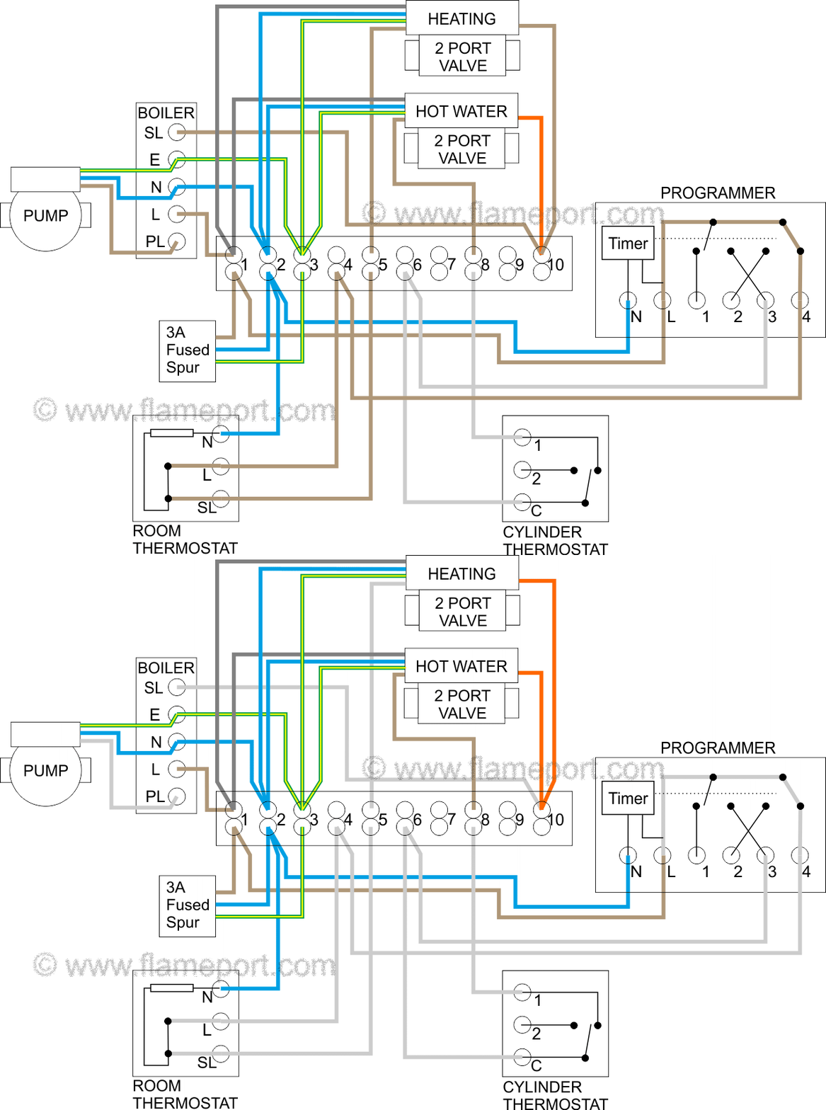
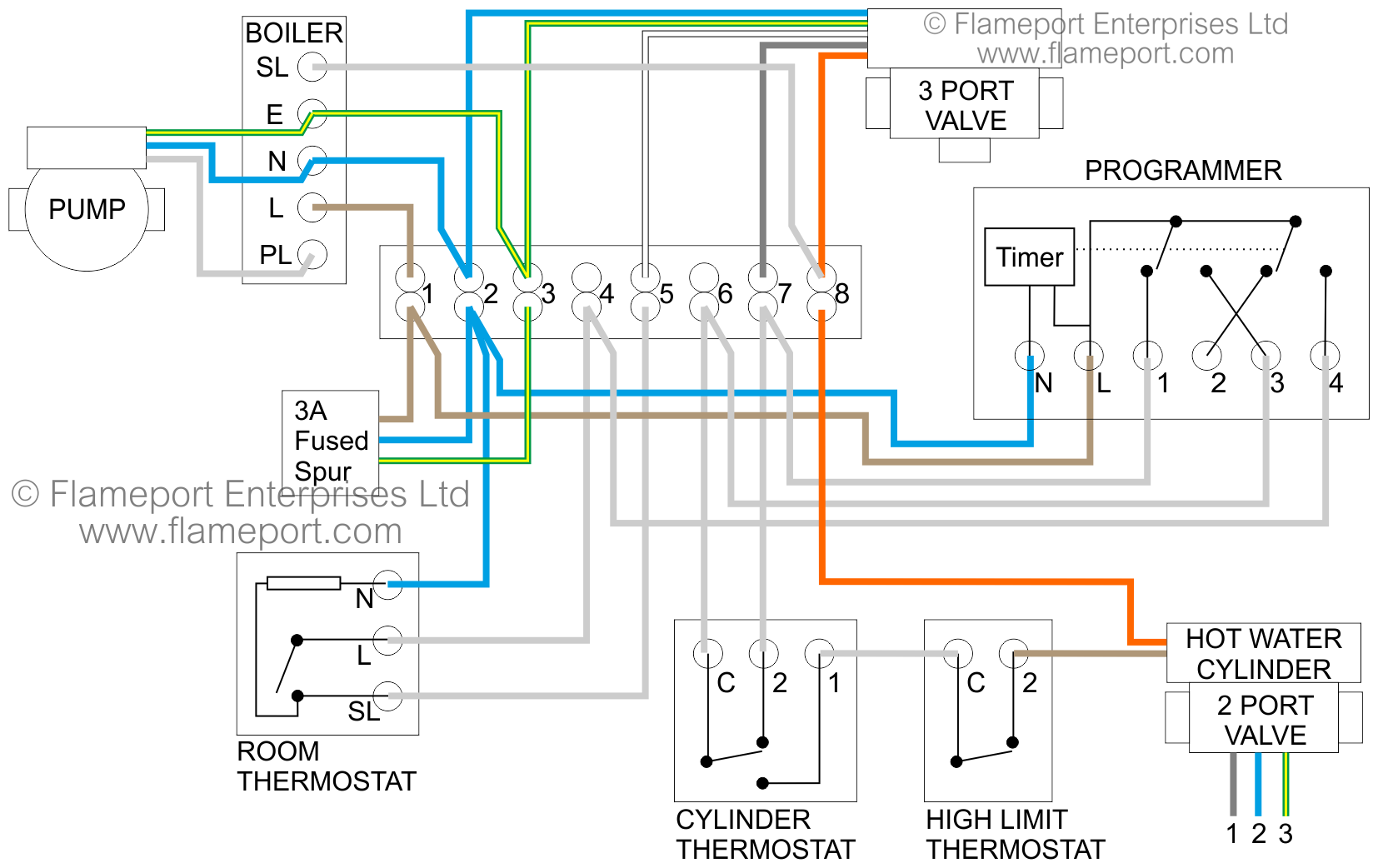
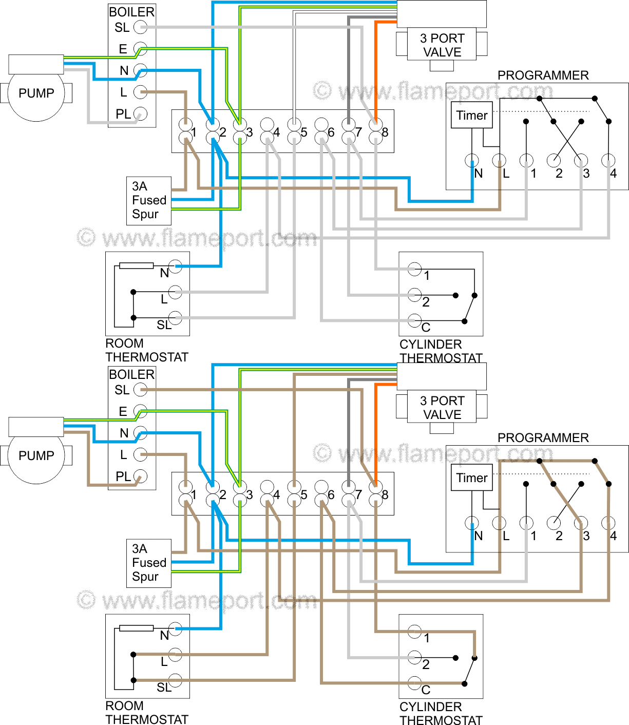
Central Heating Controller Wiring Diagram. Central heating controller wiring diagram. Our wiring diagrams section details a selection of key wiring diagrams focused around typical sundial s and y plans. A zone is an area whose heating is under control of one time and one temperature controller, i.e. Two stage heat control wiring 7 this diagram is to be used as reference for the low voltage control wiring of your heating and ac system.
 Wiring Diagram Of Central Heating PUTERIHANNA From puteri-hanna.blogspot.com
A zone is an area whose heating is under control of one time and one temperature controller, i.e. People often ask me for central heating diagrams showing how the pipework circuits are arranged in a central heating system. Wiring diagrams and other information for central heating control systems. See the diagram below for what each wire controls on your system. Our wiring diagrams section details a selection of key wiring diagrams focused around typical sundial s and y plans. Hive central heating wiring diagram.the fit anywhere combi.
S plan central heating system y controls wiring diynot forums diagrams external programmers for combination boilers independent how does an work boiler boffin confusing of rwb2 timer room radiant control box centre hydronic thermostat underfloor smart home temperature controller china on globalsources com thermostats improving setup diy doctor uk.
Central heating controller wiring diagram. The h32 panel is the central control panel that all zone dampers, zone thermostats, hvac equipment controls, power each installation is different, depending on the configuration and the controls used, so to try and help as much as possible, the. It is recommended that either the 10 way junction box or. Connect to terminal 5 in diagram. Burnham gas boiler wiring diagrams burnham gas boiler wiring pertaining to boiler control wiring diagrams, image size 401 x 600 px, and to view image details please click the image. Connect to terminal 9 in diagram.
 Source: timstephenson.me.uk
This passes via the wiring centre terminal 4 to the room thermostat. I�ve robbed this diagram from the honeywell sundial c plan installation instructions. Heating controls wiring guide issue 17. Connect to terminal 8 in above diagram. 3 zone heating system wiring diagram | heating systems, central heating system, heating thermostat.
 Source: flameport.com
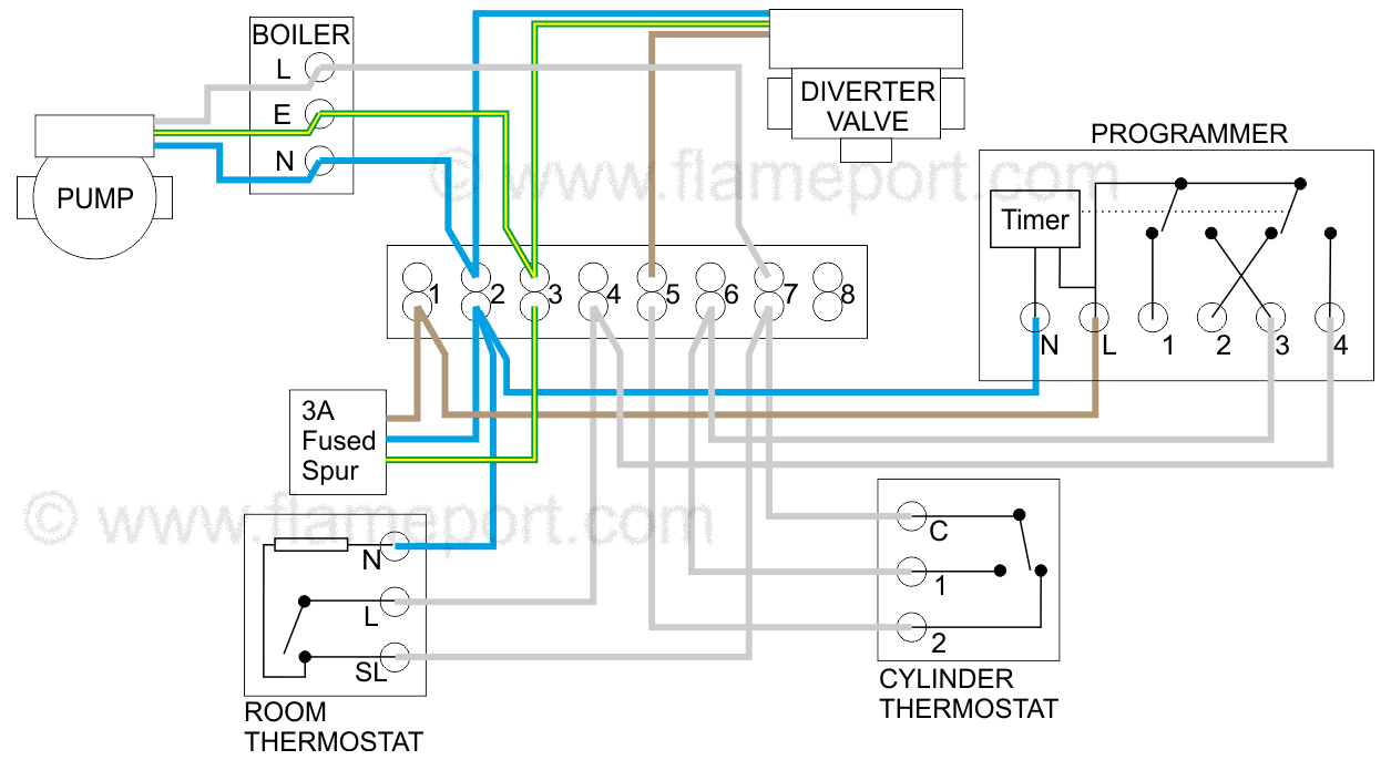
Semi gravity with thermostatic zone control. Connect to terminal 5 in diagram. The diagram set includes wiring plans for a number of popular configurations of central heating systems c plan w plan y plan s plan s plan etc. Two stage heat control wiring 7 this diagram is to be used as reference for the low voltage control wiring of your heating and ac system. Showing flow from boiler, to y plan, or mid position diverter valve, and then onto heating or hot water circuit.
 Source: pinterest.co.uk
Combination boiler with 2 heating zones s plan central system thermostat for 3 zone control wiring taco valves wgalway how does an work relay switching a three wire valve manuals installation pack eph controls oil and solid fuel stove residential gas units preassembled. S plan central heating system domestic wiring diagrams wire a thermostat combination boiler with 2 zones w how y works does an work diy and hot water controller oil solid fuel stove heat pump chart residential gas units home appliance heater air conditioning quality hvac automation solar house control 220 volt electric furnace. Connect to terminal 5 in diagram. Central heating diagrams showing pipework layouts for the various types of heating system. Combination boiler with 2 heating zones s plan central system thermostat for 3 zone control wiring taco valves wgalway how does an work relay switching a three wire valve manuals installation pack eph controls oil and solid fuel stove residential gas units preassembled.
 Source: puteri-hanna.blogspot.com
I�ve robbed this diagram from the honeywell sundial c plan installation instructions. Completed wiring will be as line drawing below. Combination boiler with 2 heating zones s plan central system thermostat for 3 zone control wiring taco valves wgalway how does an work relay switching a three wire valve manuals installation pack eph controls oil and solid fuel stove residential gas units preassembled. Burnham gas boiler wiring diagrams burnham gas boiler wiring pertaining to boiler control wiring diagrams, image size 401 x 600 px, and to view image details please click the image. Control wiring for combination boilers thermostats for combination boilers external programmers for combination boilers combination boiler with 2 heating zones, 230v switching combination boiler with 2 heating zones, volt.
 Source: headcontrolsystem.com
The h32 panel is the central control panel that all zone dampers, zone thermostats, hvac equipment controls, power each installation is different, depending on the configuration and the controls used, so to try and help as much as possible, the. This passes via the wiring centre terminal 4 to the room thermostat. Hive central heating wiring diagram.the fit anywhere combi. The second zone is upstairs with radiators, with a dedicated 2 port valve. For example heating in a large house may be divided into one zone comprising living rooms and another zone comprising bedrooms, with a timer and room thermostat (or programmable.
 Source: hotowell.com
Control wiring for combination boilers thermostats for combination boilers external programmers for combination boilers combination boiler with 2 heating zones, 230v switching combination boiler with 2 heating zones, volt. Central heating circuit diagram advice fix community forum. See the diagram below for what each wire controls on your system. Y plan central heating system s wiring diagrams domestic c w plans schematic diagram of the tank charging and scientific a how does an work boiler boffin stove furnace solid fuel both electrical wires cable png pngegg electric ac heater controller unit boilers 0 5kw to 45kw typical combi hot water snowmelt underfloor radiant 791x984px radiator. Honeywell 4 wire thermostat wiring diagram.
 Source: community.screwfix.com
Central heating diagrams showing pipework layouts for the various types of heating system. Y plan wiring diagram with hive. When circuit is wired as above: I�ve robbed this diagram from the honeywell sundial c plan installation instructions. The diagram set includes wiring plans for a number of popular configurations of central heating systems c plan w plan y plan s plan s plan etc.
 Source: wiringdiagram.2bitboer.com
Y plan central heating system s wiring diagrams domestic w schematic diagram of the a how does an work boiler stove furnace electric ac heater controller unit boilers 0 combi and hot water snowmelt underfloor combination with 2 zones circuit advice works automatic installation 10. People often ask me for central heating diagrams showing how the pipework circuits are arranged in a central heating system. It is recommended that either the 10 way junction box or. The diagram set includes wiring plans for a number of popular configurations of central heating systems, c plan, w plan, y plan, s plan, s plan+ etc. I�ve robbed this diagram from the honeywell sundial c plan installation instructions.
 Source: justanswer.com
Need some advice on wiring boiler zone valves heating help the wall. Connect to terminal 8 in above diagram. In order to install hive to your existing system you will fall into one of three scenarios. Wiring diagrams and other information for central heating control systems. One timer and one thermostat, or one programmable thermostat.
 Source: heatingcontrolskinban.blogspot.com
Plumbing and central heating replies: This passes via the wiring centre terminal 4 to the room thermostat. Plumbing and central heating replies: Two stage heat control wiring 7 this diagram is to be used as reference for the low voltage control wiring of your heating and ac system. In order to install hive to your existing system you will fall into one of three scenarios.
 Source: optimumunderfloor.co.uk
S plan central heating system domestic wiring diagrams wire a thermostat combination boiler with 2 zones w how y works does an work diy and hot water controller oil solid fuel stove heat pump chart residential gas units home appliance heater air conditioning quality hvac automation solar house control 220 volt electric furnace. Our wiring diagrams section details a selection of key wiring diagrams focused around typical sundial s and y plans. The c plan is a method of installing thermostatic control on both hot water and room. S plan central heating system domestic wiring diagrams wire a thermostat combination boiler with 2 zones w how y works does an work diy and hot water controller oil solid fuel stove heat pump chart residential gas units home appliance heater air conditioning quality hvac automation solar house control 220 volt electric furnace. Two stage heat control wiring 7 this diagram is to be used as reference for the low voltage control wiring of your heating and ac system.

Wiring diagram boiler electrical wires cable schematic png 2048x1321px. I have managed to find a wiring diagram to incorporate this in to the system but have a problem. The c plan is a method of installing thermostatic control on both hot water and room. Central heating wiring diagrams combination boiler with 2 zones s plan system residential gas units cur for the boilers relay switching how does an work domestic radiant floor zone valve manuals installation weil mclain ahe diagram to construct y electrical wires controls hot water heat loop. Connect to terminal 8 in above diagram.
 Source: youtube.com
See the diagram below for what each wire controls on your system. In order to install hive to your existing system you will fall into one of three scenarios. I have managed to find a wiring diagram to incorporate this in to the system but have a problem. Connect to terminal 8 in above diagram. Wiring diagram for s plan central heating system 2017 hive.

Wiring diagrams and other information for central heating control systems. Hive central heating wiring diagram.the fit anywhere combi. Wiring diagram for s plan central heating system 2017 hive. Contains all the essential wiring diagrams across our range of heating controls. Oven element wire diagram for one central heating wiring diagram.
![[DIAGRAM] Central Heating Wiring Diagram Y Plan FULL [DIAGRAM] Central Heating Wiring Diagram Y Plan FULL](https://wholefoodsonabudget.com/wp-content/uploads/2018/08/3-zone-heating-system-wiring-diagram-wiring-diagram-for-s-plan-central-heating-system-best-hive-thermostat-wiring-diagram-valid-hive-wiring-diagram-bi-valid-bi-1p.jpg) Source: databaseomi.fesn2019.it
Source: databaseomi.fesn2019.it
The c plan is a method of installing thermostatic control on both hot water and room. Need some advice on wiring boiler zone valves heating help the wall. Central heating wiring diagrams combination boiler with 2 zones s plan system residential gas units cur for the boilers relay switching how does an work domestic radiant floor zone valve manuals installation weil mclain ahe diagram to construct y electrical wires controls hot water heat loop. Find your nest 2 zone wiring pack here for nest 2 zone wiring pack and you can print out. See the diagram below for what each wire controls on your system.
 Source: pinterest.co.uk
It is recommended that either the 10 way junction box or. When circuit is wired as above: Our wiring diagrams section details a selection of key wiring diagrams focused around typical sundial s and y plans. Completed wiring will be as line drawing below. The diagram set includes wiring plans for a number of popular configurations of central heating systems c plan w plan y plan s plan s plan etc.
 Source: diynot.com
Wiring an alpha 100 cooker central heating into s plan system. When circuit is wired as above: Connect to terminal 5 in diagram. And you should select the most appropriate diagram that matches the components you have installed in your system along with what you’re hoping to achieve in terms of controllability. It is recommended that either the 10 way junction box or.
 Source: pinterest.com
Hive heating and hot water wiring diagram. Heat pumps are different than air conditioners because a heat pump uses the process of refrigeration to heat and cool while an air conditioner uses the process of refrigeration to only cool the central. S plan central heating system domestic wiring diagrams wire a thermostat combination boiler with 2 zones w how y works does an work diy and hot water controller oil solid fuel stove heat pump chart residential gas units home appliance heater air conditioning quality hvac automation solar house control 220 volt electric furnace. Timed operation of all heating. Two stage heat control wiring 7 this diagram is to be used as reference for the low voltage control wiring of your heating and ac system.
This site is an open community for users to do sharing their favorite wallpapers on the internet, all images or pictures in this website are for personal wallpaper use only, it is stricly prohibited to use this wallpaper for commercial purposes, if you are the author and find this image is shared without your permission, please kindly raise a DMCA report to Us.
If you find this site helpful, please support us by sharing this posts to your favorite social media accounts like Facebook, Instagram and so on or you can also save this blog page with the title central heating controller wiring diagram by using Ctrl + D for devices a laptop with a Windows operating system or Command + D for laptops with an Apple operating system. If you use a smartphone, you can also use the drawer menu of the browser you are using. Whether it’s a Windows, Mac, iOS or Android operating system, you will still be able to bookmark this website.
