Your Carel controller wiring diagram images are available in this site. Carel controller wiring diagram are a topic that is being searched for and liked by netizens now. You can Get the Carel controller wiring diagram files here. Download all free images.
If you’re looking for carel controller wiring diagram images information connected with to the carel controller wiring diagram keyword, you have pay a visit to the right site. Our website frequently gives you suggestions for viewing the highest quality video and image content, please kindly search and locate more enlightening video articles and images that match your interests.
Carel Controller Wiring Diagram. Μc2se user manual.pdf 1.55mb carel case controller.pdf 5.10mb μc2se for process chiller.pdf 2.18mb For the 25 to 45kg/h models (compliant with din 19535, uni 8451/8452). Ignition wiring diagram for alliis chlamers ca tractor; Bypass damper control and wiring is by others.
 Carel Controller Wiring Diagram From schematron.org
For the 25 to 45kg/h models (compliant with din 19535, uni 8451/8452). An electrical logic diagram is shown in table 1. Ir33+ platform ir33+, ir33+wide, ir33+ small wide which are required/indicated in the user manual, may cause the final product to malfunction. The valent or innovent controller receives 24 vac power from a transformer on the main control panel and is energized when the main disconnect is on the size of the carel c pco board varies with unit configuration figure 1: The evaporator is a flooded shell and tube design using enhanced surface finned copper tubes. It is constructed in accordance with asme code for a refrigerant side working pressure of 1320kpa and is tested for a maximum water‐side pressure of 1000 kpa.
Diehard 200 amp battery charger jump starter wiring diagram;
Skip to the beginning of the images gallery. General connection diagram is a practical example for preparing the unit wiring diagram that fully. Hitachi wired control for two units. Carel bases the development of its products on decades of experience. To know which output is associated with the fan, see the wiring diagram for the “easy” model used (see par. It is constructed in accordance with asme code for a refrigerant side working pressure of 1320kpa and is tested for a maximum water‐side pressure of 1000 kpa.
 Source: wiringall.com
Carel temperature controller full wiring diagram. The front cover is secured by a capture screw located underneath the carel logo. The evaporator shell is insulated with 19mmsed clo ‐cell foam (max k factor of 0. Connect new probes to controller as shown in wiring diagram. Exn unipolar stepper motor driven electronic expansion valves are for precise control of refrigerant mass flow in heat pumps,.
 Source: manualslib.com
Connect the power cable and digital input cable: Electronic expansion valve hvac ,eev|. The valent or innovent controller uses a. The tabs at the back will snap into place and lock the controller. For the 25 to 45kg/h models (compliant with din 19535, uni 8451/8452).
 Source: wiringall.com
It is constructed in accordance with asme code for a refrigerant side working pressure of 1320kpa and is tested for a maximum water‐side pressure of 1000 kpa. Ir33+ platform ir33+, ir33+wide, ir33+ small wide which are required/indicated in the user manual, may cause the final product to malfunction. Carel bases the development of its products on decades of experience. Then simply lift the front cover and pull out to remove it. The drain water is connected using a section of rubber or plastic hose resistant to 100°c, with a recommended inside diameter of 32 mm or 40 mm.

2.9 of 17/12/2015 7 1. It is constructed in accordance with asme code for a refrigerant side working pressure of 1320kpa and is tested for a maximum water‐side pressure of 1000 kpa. External terminal (address=32), communication is established and the. Ir33+ platform ir33+, ir33+wide, ir33+ small wide which are required/indicated in the user manual, may cause the final product to malfunction. The evaporator is a flooded shell and tube design using enhanced surface finned copper tubes.
 Source: schematron.org
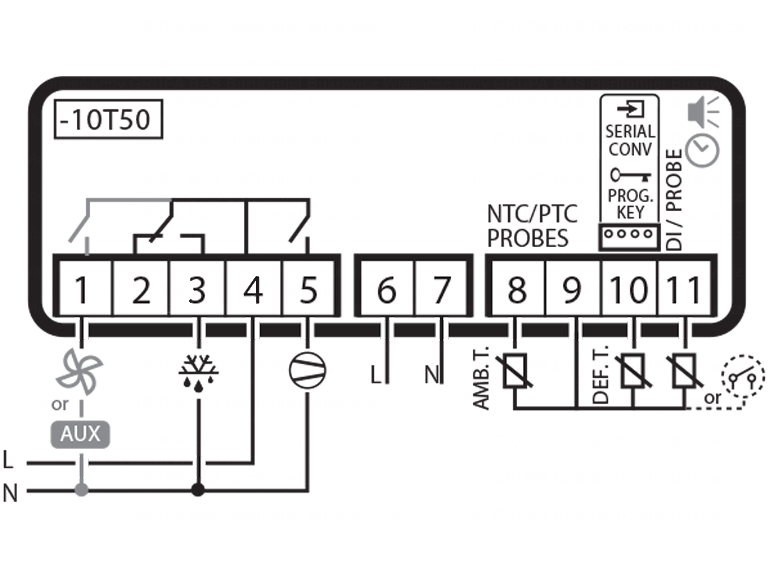
Jl 2 250.1 wiring diagram; • power supply, normally the same as the. To know which output is associated with the fan, see the wiring diagram for the “easy” model used (see par. Then simply lift the front cover and pull out to remove it. The valent or innovent controller uses a.
 Source: alleklima.pl
“2.2 electrical connections” page 11). The evaporator fan control temperature is measured by probe 2, (connector 10). Twist the carel logo to reveal the screw, and use a phillips head screwdriver to remove it. The front cover is secured by a capture screw located underneath the carel logo. Ignition wiring diagram for alliis chlamers ca tractor;
 Source: schematron.org
The tabs at the back will snap into place and lock the controller. In this video we look at the wiring process for installing a dixell temperature control that are most commonly found on reach in coolers and freezers on comm. • place the controller on the din rail and press it down gently. Diehard 200 amp battery charger jump starter wiring diagram; Standard modular chiller hp 1 / 8 compressors with carel driver carel code +030221251 rel.
 Source: schematron.org
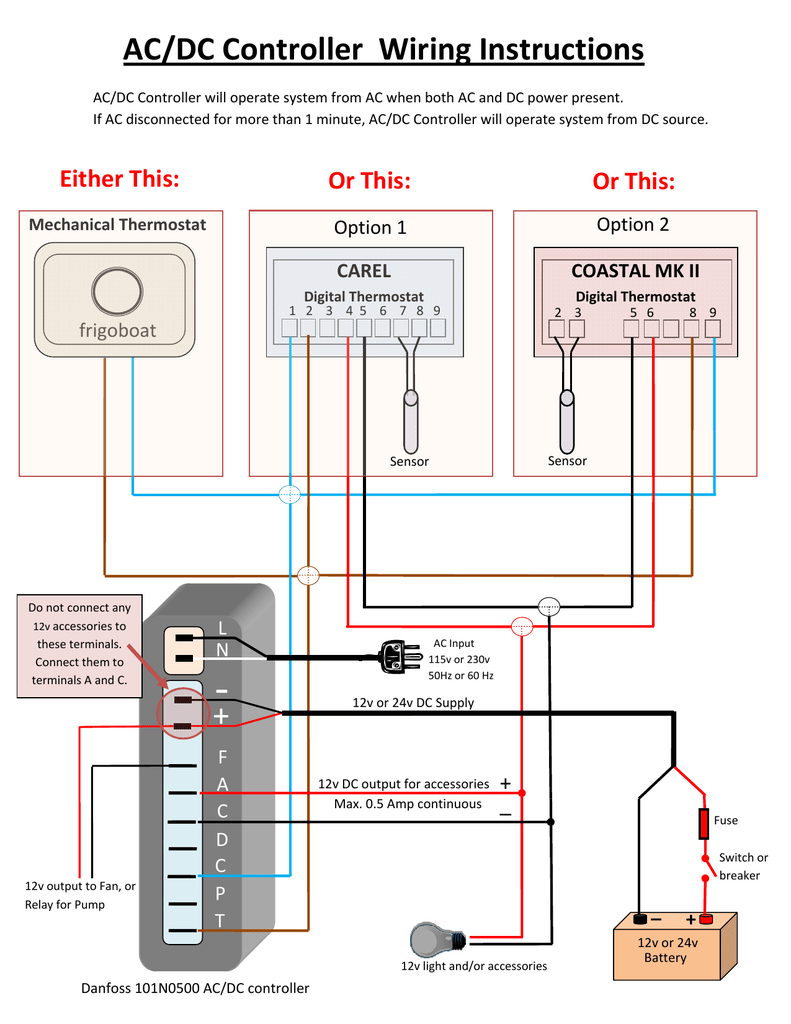
Carel bases the development of its products on decades of experience. The tabs at the back will snap into place and lock the controller. • place the controller on the din rail and press it down gently. Control can be set as on/off (proportional) or proportional, integral and Carel controller electrical wiring diagram be sure all power sources are turned off before checking the electric wiring or appliances to.
 Source: hanishaari.blogspot.com
Jl 2 250.1 wiring diagram; Carel bases the development of its products on decades of experience. Diehard 200 amp battery charger jump starter wiring diagram; These parameters are not available in the compact models. “2.2 electrical connections” page 11).

Electronic expansion valve hvac ,eev|. An electrical logic diagram is shown in table 1. Improved management of customised rotation; “2.2 electrical connections” page 11). 2.9 of 17/12/2015 7 1.
 Source: diagramweb.net
Electronic expansion valve hvac ,eev|. This is a instructional video on how to program our carel pjez* easy digital controller Everbilt sprinkler pump wiring diagram; Airedale easicool downflow eev control. The ssr on the dcm control is pilot duty, and is used to drive a larger current rated external ssr.
 Source: diagramweb.net
Bypass damper control and wiring is by others. • power supply, normally the same as the. Pioneer deh 245 wiring diagram; 2.9 of 17/12/2015 7 1. For the maximum length, see the technical specifications;
 Source: diagramweb.net
The sensors can have an alternating current (12 to 24 vac) or direct current (9 to 30 vdc) power supply. Accordance with all appropriate manuals and wiring diagrams, and started up by a qualified carel usa. The evaporator fan control temperature is measured by probe 2, (connector 10). An electrical logic diagram is shown in table 1. Sl refrigeration unit (skope carel ir33 controller).
 Source: studylib.net
Skip to the end of the images gallery. The valent or innovent controller uses a. Aguilar obp 3 wiring diagram; To know which output is associated with the fan, see the wiring diagram for the “easy” model used (see par. These parameters are not available in the compact models.
 Source: diagramweb.net
Ignition wiring diagram for alliis chlamers ca tractor; For the maximum length, see the technical specifications; Standard modular chiller hp 1 / 8 compressors with carel driver carel code +030221251 rel. Then simply lift the front cover and pull out to remove it. कैरल कंट्रोलर की वायरिंग सीखें हिन्दी में।। carel easy freeze pjez.
 Source: manualzz.com
Improved management of customised rotation; An electrical logic diagram is shown in table 1. Carel electronic expansion valves e2v with. Accordance with all appropriate manuals and wiring diagrams, and started up by a qualified carel usa. External terminal (address=32), communication is established and the.
![[DIAGRAM in Pictures Database] Ps2 Slim Schematic Wiring [DIAGRAM in Pictures Database] Ps2 Slim Schematic Wiring](http://www.joppaglass.com/elements/kiln_control/CONT_WIRING_DIAG.jpg) Source: crowdfunding.demo.agriya.com
Source: crowdfunding.demo.agriya.com
For the 25 to 45kg/h models (compliant with din 19535, uni 8451/8452). The valent or innovent controller receives 24 vac power from a transformer on the main control panel and is energized when the main disconnect is on the size of the carel c pco board varies with unit configuration figure 1: Return it in reverse order. Standard modular chiller hp 1 / 8 compressors with carel driver carel code +030221251 rel. • place the controller on the din rail and press it down gently.
 Source: schematron.org
• power supply, normally the same as the. Carel temperature controller full wiring diagram. Control can be set as on/off (proportional) or proportional, integral and Everbilt sprinkler pump wiring diagram; • power supply, normally the same as the.
This site is an open community for users to submit their favorite wallpapers on the internet, all images or pictures in this website are for personal wallpaper use only, it is stricly prohibited to use this wallpaper for commercial purposes, if you are the author and find this image is shared without your permission, please kindly raise a DMCA report to Us.
If you find this site convienient, please support us by sharing this posts to your favorite social media accounts like Facebook, Instagram and so on or you can also save this blog page with the title carel controller wiring diagram by using Ctrl + D for devices a laptop with a Windows operating system or Command + D for laptops with an Apple operating system. If you use a smartphone, you can also use the drawer menu of the browser you are using. Whether it’s a Windows, Mac, iOS or Android operating system, you will still be able to bookmark this website.
