Your Car gps tracker wiring diagram images are available. Car gps tracker wiring diagram are a topic that is being searched for and liked by netizens now. You can Find and Download the Car gps tracker wiring diagram files here. Download all free photos.
If you’re searching for car gps tracker wiring diagram pictures information related to the car gps tracker wiring diagram topic, you have visit the right blog. Our site always gives you suggestions for downloading the highest quality video and picture content, please kindly surf and find more enlightening video articles and images that match your interests.
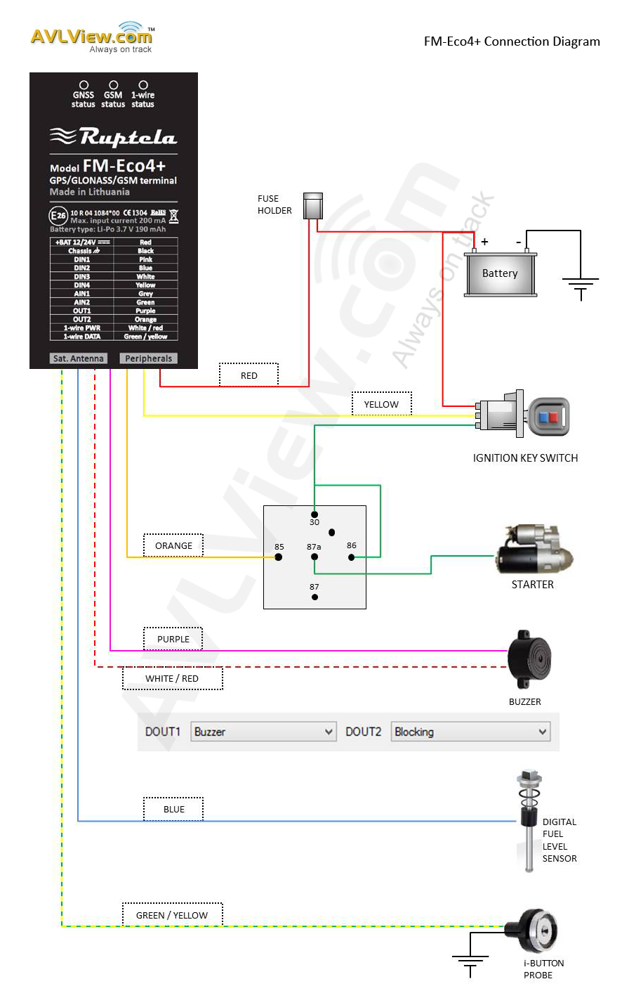
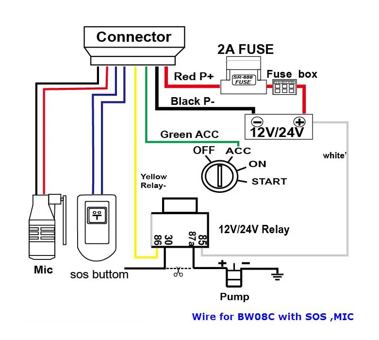
Car Gps Tracker Wiring Diagram. Fitting covert gps vehicle tracker is the secrecy element. Electric vehicle gps tracker installation problem gt800 user manual å ¾å½ 2 shenzhen con information technology disguise as relay easy to hide factory vehicletracker system. Occasionally, the cables will cross. Connect everything before plugging harness into the evo device.
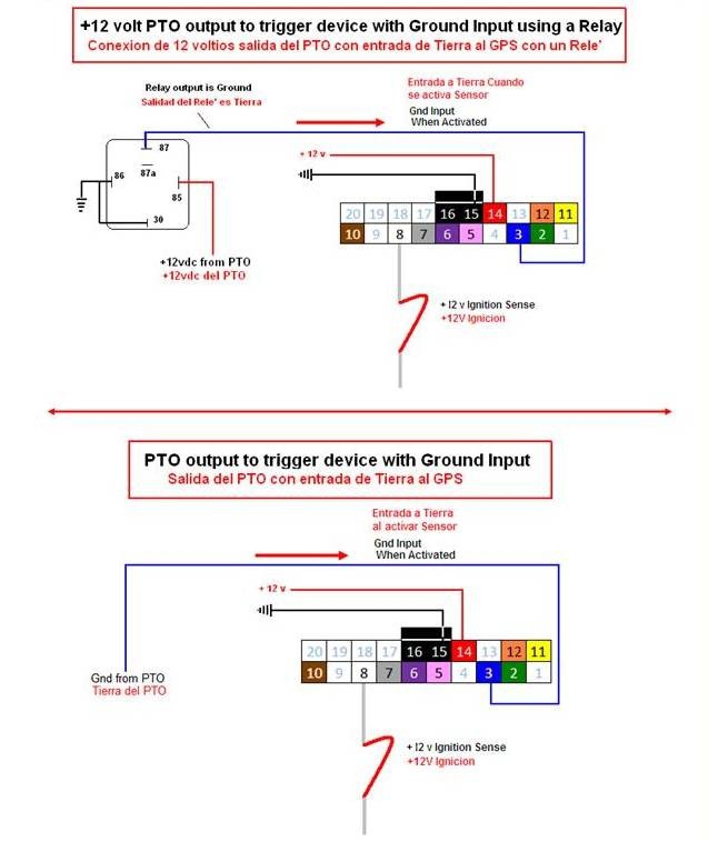
 PTO Wiring Diagram GPS TrackersGPS Trackers From morsegps.com
Electric vehicle gps tracker installation problem gt800 user manual å ¾å½ 2 shenzhen con information technology disguise as relay easy to hide factory vehicletracker system noran. Next find the ignition wire on the vehicle and connect it to the ignition input in the fuse box. There are also other components such as floor, switch, motor, and inductor. Next find the ignition/accessory wire on the vehicle (see wiring diagram for specific device) and connect it to the white wire on the device. This gps tracker can be used as car alarm, fleet management, driver management etc, it can be used for tracking cars, company vehicles, buses, taxis, trucks, etc. Tracker pro guide wiring diagrams.
In this video, we will make a vehicle tracking system using arduino.we can.
Send sms command “fix030s005n +password” to the trac ker device, it will report the latitude & longitude at 30s intervals for 5 times. Connect the black wire to ground. 8 battery / output control connection analog signal diagram 1 negative trigger connection car type positive trigger connection car type door negative trigge rconnection door light door positive trigge rconnection door light diagram 2 diagram 3 rela y 1 rela y 2 car left signal wire left turn light car right signal wire right turn light Slot car corner offers a free, downloadable wiring diagram for trackmate single call button. Wiring diagrams comprise certain things: Electric vehicle gps tracker installation problem gt800 user manual å ¾å½ 2 shenzhen con information technology disguise as relay easy to hide factory vehicletracker system noran international co ltd tr car we track tracke wholer from hyderabad the latest gt06n you should have jimi iot motorcycle tlt 2h b g05 coban.
![]() Source: diagramweb.net
Source: diagramweb.net
This allows you to connect your mini tracker to an external power source such as a. It shows the components of the circuit as simplified shapes, and the capability and signal associates in the company of the devices. Wiring diagram line we are make source the schematics, wiring diagrams and technical photos. Occasionally, the cables will cross. This allows you to connect your mini tracker to an external power source such as a.
 Source: edu-apps.herokuapp.com
Symbols that represent the ingredients in the circuit, and lines that represent the connections between them. Symbols that represent the ingredients in the circuit, and lines that represent the connections between them. A wiring diagram is a type of schematic which uses abstract pictorial symbols showing all of the interconnections of components in a system. Gps tracker wiring diagram wiring diagram line wiring diagram. Slot car corner offers a free, downloadable wiring diagram for trackmate single call button.

Locate the vehicle’s ignition wire (reference the vehicle’s wiring diagram in order to locate). Verify the ignition wire by measuring the operating voltage while the key is turned to the on or start position (the voltage should read 0 vdc when the key is in the o˚ position, and typically between 11v and 14v when in the on position. Wiring diagram for gps tracker wiring diagram line wiring diagram. Wiring guide for tracking device: The most common components are capacitor, resistor, and battery.
 Source: wiring89.blogspot.com
6.9 auto track continuously 6.9.1 track with limited times upon time interval: Red goes to a constant power connection with a voltage between +12v and +24v. Choose a mounting location high in the dash with no metal obstructions above the device. Verify the ignition wire by measuring the operating voltage while the key is turned to the on or start position (the voltage should read 0 vdc when the key is in the o˚ position, and typically between 11v and 14v when in the on position). On inilex gps wiring diagram.
![]() Source: hzbooksir.com
Source: hzbooksir.com
Connect the black wire to ground. According to earlier, the traces at a passtime gps wiring diagram signifies wires. Install the device in your vehicle, connect the wiring harness to the base unit as indicated in the diagram above. An optional hard wire kit is available to purchase separately from our website. Use pc or mobile phone browser to visit the website can download or read the manual online.
 Source: morsegps.com
In this video, we will make a vehicle tracking system using arduino.we can. Electric vehicle gps tracker installation problem gt800 user manual å ¾å½ 2 shenzhen con information technology disguise as relay easy to hide factory vehicletracker system noran. A wiring diagram is a type of schematic which uses abstract pictorial symbols showing all of the interconnections of components in a system. This video will show you how to connect the power and ground wires for a vehicle gps tracking device. Choose a mounting location high in the dash with no metal obstructions above the device.
 Source: iamtreked.com
And insert it inside the tracker. Locate the vehicle’s ignition wire (reference the vehicle’s wiring diagram in order to locate). Finally, connect the ground wire on the harness to the vehicle ground (chassis). Tk102 mini gps tracker user manual (version 1.2). Choose a mounting location high in the dash with no metal obstructions above the device.
 Source: kovodym.blogspot.com
Fitting covert gps vehicle tracker is the secrecy element. This allows you to connect your mini tracker to an external power source such as a. Our company sells gps tracking devices for $119 that i. This command set must be in 3 digits and the maximum value is 255. Wiring diagram for gps tracker wiring diagram line wiring diagram.
![]() Source: gps-hebring.blogspot.com
Source: gps-hebring.blogspot.com
An optional hard wire kit is available to purchase separately from our website. All of it rides on circuit that’s being assembled. Next find the ignition/accessory wire on the vehicle (see wiring diagram for specific device) and connect it to the white wire on the device. 8 battery / output control connection analog signal diagram 1 negative trigger connection car type positive trigger connection car type door negative trigge rconnection door light door positive trigge rconnection door light diagram 2 diagram 3 rela y 1 rela y 2 car left signal wire left turn light car right signal wire right turn light Collection of gps tracker wiring diagram.

This video will show you how to connect the power and ground wires for a vehicle gps tracking device. A wiring diagram is a streamlined conventional pictorial depiction of an electrical circuit. Evo wiring [power/serial cable diagram] we’ve included a detachable wiring harness. Hard wire fleet car auto vehicle gps tracker with ignition kill switch control tracking device: Verify the ignition wire by measuring the operating voltage while the key is turned to the on or start position (the voltage should read 0 vdc when the key is in the o˚ position, and typically between 11v and 14v when in the on position).
 Source: angieplusjoe.blogspot.com
This command set must be in 3 digits and the maximum value is 255. Install the device in your vehicle, connect the wiring harness to the base unit as indicated in the diagram above. Here is a link to find vehicle wiring diagrams. Connect the constant 12 vdc power source to the red wire on the tracking device. Connect the white wire to the vehicle’s ignition or accessory power.
![]() Source: vwt4forum.co.uk
Source: vwt4forum.co.uk
Connect the black wire to ground. Locate the vehicle’s ignition wire (reference the vehicle’s wiring diagram in order to locate). Wiring diagram line we are make source the schematics, wiring diagrams and technical photos. Next find the ignition/accessory wire on the vehicle (see wiring diagram for specific device) and connect it to the white wire on the device. It shows the components of the circuit as simplified shapes, and the capability and signal associates in the company of the devices.
 Source: angieplusjoe.blogspot.com
The tracker has to be connected to a power source providing 9vv dc. Also, need a second wiring diagram which will allow a switch to shut power off/on during the last lap of race. Here is a link to find vehicle wiring diagrams. Wiring diagram line we are make source the schematics, wiring diagrams and technical photos. Hard wire fleet car auto vehicle gps tracker with ignition kill switch control tracking device:

This gps tracker can be used as car alarm, fleet management, driver management etc, it can be used for tracking cars, company vehicles, buses, taxis, trucks, etc. And insert it inside the tracker. Wiring diagram line we are make source the schematics, wiring diagrams and technical photos. There are also other components such as floor, switch, motor, and inductor. Gps tracker wiring diagram wiring diagram line wiring diagram.
![]() Source: mainetreasurechest.com
Source: mainetreasurechest.com
It reveals the parts of the circuit as streamlined forms and the power as well as signal connections in between the gadgets. Wiring guide for tracking device: Use the poke and wrap technique to connect the constant 12 vdc power source to the red wire on the tracking device. Locate the vehicle’s ignition wire (reference the vehicle’s wiring diagram in order to locate). According to earlier, the traces at a passtime gps wiring diagram signifies wires.
 Source: wiring89.blogspot.com
3.3 device wiring diagram cont. Theft fleet trailer security repo new car dealer finance rentals marine personal pet. According to earlier, the traces at a passtime gps wiring diagram signifies wires. Wiring diagram for gps tracker wiring diagram line wiring diagram. Make sure all wires are routed neatly throughout the dash.
 Source: edu-apps.herokuapp.com
Symbols that represent the ingredients in the circuit, and lines that represent the connections between them. Theft fleet trailer security repo new car dealer finance rentals marine personal pet. This video will show you how to connect the power and ground wires for a vehicle gps tracking device. Red goes to a constant power connection with a voltage between +12v and +24v. This gps tracker can be used as car alarm, fleet management, driver management etc, it can be used for tracking cars, company vehicles, buses, taxis, trucks, etc.
 Source: skemaskala.blogspot.com
A wiring diagram is a streamlined conventional pictorial depiction of an electrical circuit. Tracker pro guide wiring diagrams. Verify the ignition wire by measuring the operating voltage while the key is turned to the on or start position (the voltage should read 0 vdc when the key is in the o˚ position, and typically between 11v and 14v when in the on position). Connect the black wire to ground. Slot car corner offers a free, downloadable wiring diagram for trackmate single call button.
This site is an open community for users to submit their favorite wallpapers on the internet, all images or pictures in this website are for personal wallpaper use only, it is stricly prohibited to use this wallpaper for commercial purposes, if you are the author and find this image is shared without your permission, please kindly raise a DMCA report to Us.
If you find this site helpful, please support us by sharing this posts to your own social media accounts like Facebook, Instagram and so on or you can also save this blog page with the title car gps tracker wiring diagram by using Ctrl + D for devices a laptop with a Windows operating system or Command + D for laptops with an Apple operating system. If you use a smartphone, you can also use the drawer menu of the browser you are using. Whether it’s a Windows, Mac, iOS or Android operating system, you will still be able to bookmark this website.


