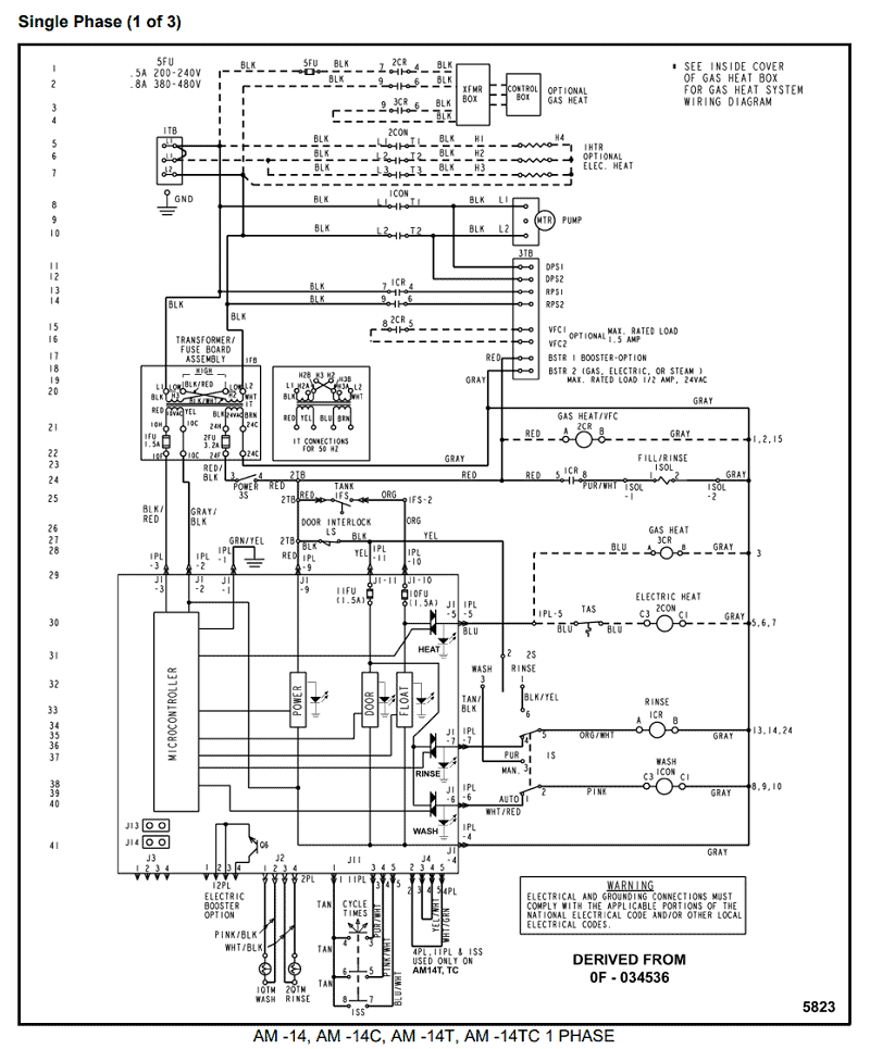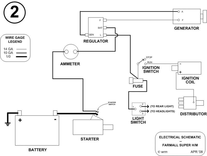
Your Capacitor panel control wiring diagram images are ready. Capacitor panel control wiring diagram are a topic that is being searched for and liked by netizens now. You can Find and Download the Capacitor panel control wiring diagram files here. Get all royalty-free photos.
If you’re searching for capacitor panel control wiring diagram pictures information linked to the capacitor panel control wiring diagram topic, you have come to the ideal site. Our site always gives you suggestions for downloading the highest quality video and picture content, please kindly hunt and find more informative video content and graphics that fit your interests.
Capacitor Panel Control Wiring Diagram. Improper connection may result in damage to the motor and capacitors. Wiring diagram for electric motor with capacitor best single phase. There are two ways to control the circuit manual mode and auto mode. Single phase motor wiring diagram with capacitor start capacitor run.
 New Inverter Wiring Diagram Pdf Ac wiring, Electrical From pinterest.com
Unique wiring diagram 220v 3 wire outlet 3 wire 220v i replaced my old 2hp pump today and when opening the old toggle switch box, there […] 4oz bottle round metal 17oz bottle round plastic. Pump not submerged check water level in well. Options selected may increase enclosure size and change component layout. The other thing that you will get a circuit diagram would be traces. When power is on, the circuit becomes closed.
Power and control wiring diagram.
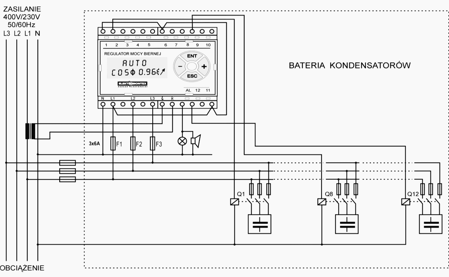
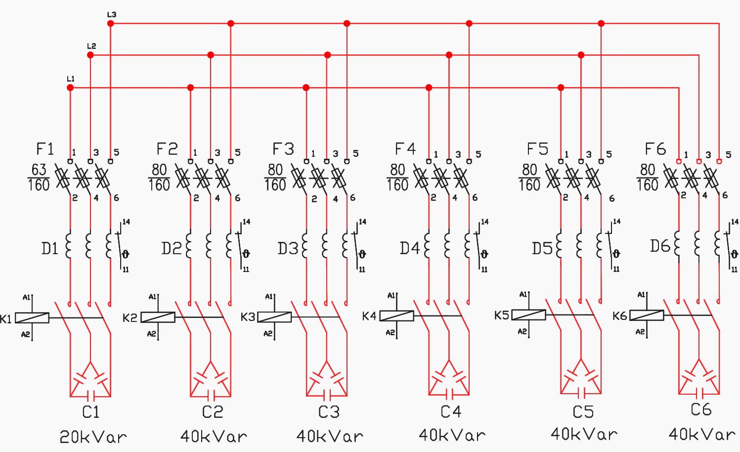
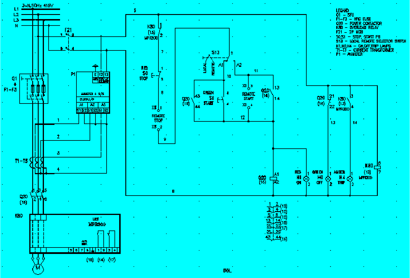
Apfc panel power circuit explanation in detail | apfc panel wiring diagram| capacitor calculations. Wiring diagram book a1 15 b1 b2 16 18 b3 a2 b1 b3 15 supply voltage 16 18 l m h 2 levels b2 l1 f u 1 460 v f u 2 l2 l3 gnd h1 h3 h2 h4 f u 3 x1a f u 4 f u 5 x2a r power on optional x1 x2115 v 230 v h1 h3 h2 h4 optional connection electrostatically shielded transformer f u 6. This all are connected in series. There are three switch f use units are connected to the supply. In this figure, we can see that there are capacitor bank, inductor, power contactor, and fuse. When auto manual switch manual terminal side km1 is energize and convert in no to nc then as per figure (3) km1 works as nc when we press the start button pb (push button) then kc contactor is energized and kc contactor work no to nc and capacitor connect with the supply this process is totally is manually and to disconnect the capacitor press the stop p.b then kc.
 Source: innovationdiscoveries.space
It is also common for a control cabinet to supply a higher voltage to other equipment, such as motors. The capacitor bank modes are manual, filo, balanced, and best fit. 4oz bottle round metal 17oz bottle round plastic. George fazio reader contributed comments on failed starter capacitor diagnosis by noting the bulged capacitor ends. A wiring diagram is a simplified traditional photographic depiction of an electric circuit.
 Source: wholefoodsonabudget.com
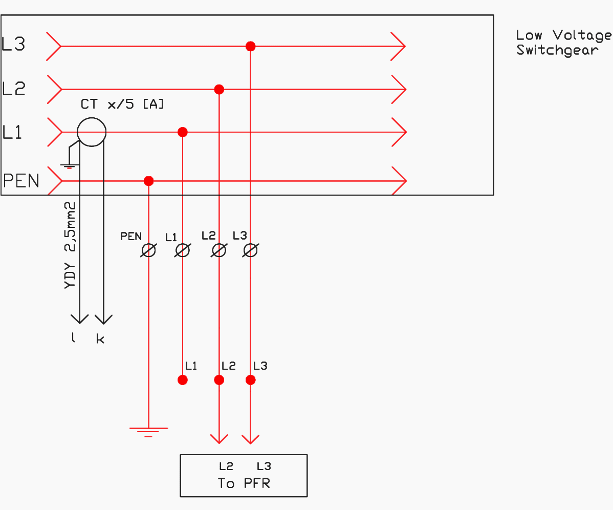
(a) auxiliary supply to rpm please connect. Warnings and cautions warnings in this manual indicate potential hazardous situations that can result in literature, and wiring diagram numbers. Apfc panel power circuit explanation in detail | apfc panel wiring diagram| capacitor calculations. Connection for the apfc panel. Single phase motor wiring diagram with capacitor start capacitor run.
 Source: pinterest.com
4oz bottle round metal 17oz bottle round plastic. It is also common for a control cabinet to supply a higher voltage to other equipment, such as motors. Step by tutorial for building capacitor bank and reactive power compensation panel eep working symbol calculation its applications wiring modes alpes technologies electrical4u. Hope you can read it. There are three switch f use units are connected to the supply.
 Source: diagramweb.net
Duplex pump control panel wiring diagram inspirational dump trailer. It is also common for a control cabinet to supply a higher voltage to other equipment, such as motors. Dashed lines indicate a single purchased component. 3 phase capacitor bank wiring diagram wiring diagram is a simplified conventional normal pictorial representation of an electrical circuit it shows the components of the circuit as simplified shapes and the expertise and signal friends between the devices. Schematic of the three phase 200 kvar 415 v apfc panel with list scientific diagram step by tutorial for building capacitor bank and reactive power compensation eep wiring modes alpes technologies connection diagrams factor correction capacitors guide circuit.
 Source: 2020cadillac.com
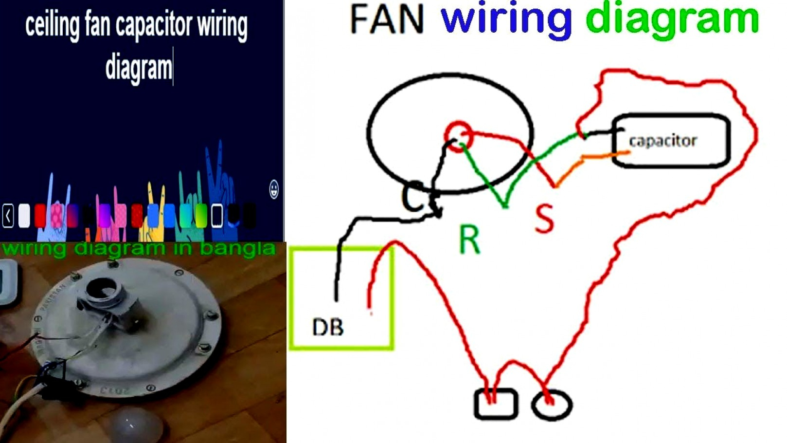
Step by tutorial for building capacitor bank and reactive power compensation panel eep working symbol calculation its applications wiring modes alpes technologies electrical4u. Schematic/wiring diagram and pump specification label are located inside the panel. Herm on capacitor goes to the start winding on the compressor, fan on capacitor goes to brown fan wire that goes to the fan, and. The other thing that you will get a circuit diagram would be traces. When power is on, the circuit becomes closed.
 Source: electrical-engineering-portal.com
There are three switch f use units are connected to the supply. There are three switch f use units are connected to the supply. 4oz bottle round metal 17oz bottle round plastic. Tomatic power factor controller (apfc) is to be. The trane this is one the paper wiring diagram that came with the motor.installation, owner, and diagnostic manual local trane representative.
 Source: pinterest.com
Note that symbols are discussed in detail later). With this sort of an illustrative guide, you’ll be able to troubleshoot, stop, and complete your tasks without difficulty. Unique wiring diagram 220v 3 wire outlet 3 wire 220v i replaced my old 2hp pump today and when opening the old toggle switch box, there […] The trane this is one the paper wiring diagram that came with the motor.installation, owner, and diagnostic manual local trane representative. Step by tutorial for building capacitor bank and reactive power compensation panel eep working symbol calculation its applications wiring modes alpes technologies electrical4u.
 Source: electrical-engineering-portal.com
With this sort of an illustrative guide, you’ll be able to troubleshoot, stop, and complete your tasks without difficulty. Diagram at the rear side of apfc controller. There are two ways to control the circuit manual mode and auto mode. The first component is symbol that indicate electrical element in the circuit. 4oz bottle round metal 17oz bottle round plastic.
 Source: pinterest.com
Incorrect voltage see d 4. There are two ways to control the circuit manual mode and auto mode. Tomatic power factor controller (apfc) is to be. Wiring diagram book a1 15 b1 b2 16 18 b3 a2 b1 b3 15 supply voltage 16 18 l m h 2 levels b2 l1 f u 1 460 v f u 2 l2 l3 gnd h1 h3 h2 h4 f u 3 x1a f u 4 f u 5 x2a r power on optional x1 x2115 v 230 v h1 h3 h2 h4 optional connection electrostatically shielded transformer f u 6. Pump not submerged check water level in well.
 Source: wholefoodsonabudget.com
Rule of thumb on wiring the capacitor is: By londa woodson | december 13, 2020. There are two things which are going to be present in any single phase motor wiring diagram with capacitor. L1 and l2 are designated as the two connection points representing the two electricity flow path inherent with single phase circuits where a single phase supply voltage is fed to the motors internal circuit. Control wiring diagram of apfc panel schematron org.
 Source: siprotech.com
There are two ways to control the circuit manual mode and auto mode. Usually, the wiring diagram is glued to one of the panels on the air conditioner. Control wiring diagram of apfc panel schematron org. There are two things which are going to be present in any single phase motor wiring diagram with capacitor. Wiring diagram book a1 15 b1 b2 16 18 b3 a2 b1 b3 15 supply voltage 16 18 l m h 2 levels b2 l1 f u 1 460 v f u 2 l2 l3 gnd h1 h3 h2 h4 f u 3 x1a f u 4 f u 5 x2a r power on optional x1 x2115 v 230 v h1 h3 h2 h4 optional connection electrostatically shielded transformer f u 6.
 Source: schematron.org
Note that symbols are discussed in detail later). There are two ways to control the circuit manual mode and auto mode. Capacitor bank control wiring diagram wiring diagram line wiring diagram. The capacitor bank modes are manual, filo, balanced, and best fit. Step 1 is wired to output 1 (capacitor bank step 1 contact) of the micrologix controller and step 10 is wired to output 10 (capacitor bank step 10 contact).
 Source: pinterest.com
In the normal condition, the power contactor is open. It includes directions and diagrams for various varieties of wiring techniques and other products like lights, home windows, etc. The capacitor bank modes are manual, filo, balanced, and best fit. Wiring diagram line we are make source the schematics, wiring diagrams and technical photos. Tomatic power factor controller (apfc) is to be.
 Source: pinterest.com
Capacitor (450 v) kw hp μf a b c qpc/03 1 x 230 ± 10% 0,37 0,5 4 16 170 170 75 1,1 3 phase capacitor bank wiring diagram wiring diagram is a simplified conventional normal pictorial representation of an electrical circuit it shows the components of the circuit as simplified shapes and the expertise and signal friends between the devices. Connection for the apfc panel. By londa woodson | december 13, 2020. L1 and l2 are designated as the two connection points representing the two electricity flow path inherent with single phase circuits where a single phase supply voltage is fed to the motors internal circuit.
 Source: electrical-engineering-portal.com
4oz bottle round metal 17oz bottle round plastic. Well pumps with control boxes have start and run circuits. Incorrect voltage see d 4. The other thing that you will get a circuit diagram would be traces. Diagram at the rear side of apfc controller.
 Source: alquilercastilloshinchables.info
Rule of thumb on wiring the capacitor is: Tomatic power factor controller (apfc) is to be. Free download edraw electrical diagram maker: Hope you can read it. Well pumps with control boxes have start and run circuits.
 Source: pinterest.com
Herm on capacitor goes to the start winding on the compressor, fan on capacitor goes to brown fan wire that goes to the fan, and. An example of a wiring diagram for a motor controller is shown in figure 1. Apfc panel power circuit explanation in detail | apfc panel wiring diagram| capacitor calculations. Herm on capacitor goes to the start winding on the compressor, fan on capacitor goes to brown fan wire that goes to the fan, and. When auto manual switch manual terminal side km1 is energize and convert in no to nc then as per figure (3) km1 works as nc when we press the start button pb (push button) then kc contactor is energized and kc contactor work no to nc and capacitor connect with the supply this process is totally is manually and to disconnect the capacitor press the stop p.b then kc.
 Source: ricardolevinsmorales.com
There are two ways to control the circuit manual mode and auto mode. Round dual capacitors on the top should be marked: Step by tutorial for building capacitor bank and reactive power compensation panel eep working symbol calculation its applications wiring modes alpes technologies electrical4u. Please refer to the product return section. Apfc panel power circuit explanation in detail | apfc panel wiring diagram| capacitor calculations.
This site is an open community for users to do sharing their favorite wallpapers on the internet, all images or pictures in this website are for personal wallpaper use only, it is stricly prohibited to use this wallpaper for commercial purposes, if you are the author and find this image is shared without your permission, please kindly raise a DMCA report to Us.
If you find this site adventageous, please support us by sharing this posts to your preference social media accounts like Facebook, Instagram and so on or you can also save this blog page with the title capacitor panel control wiring diagram by using Ctrl + D for devices a laptop with a Windows operating system or Command + D for laptops with an Apple operating system. If you use a smartphone, you can also use the drawer menu of the browser you are using. Whether it’s a Windows, Mac, iOS or Android operating system, you will still be able to bookmark this website.

