
Your Capacitor bank wiring diagram images are available in this site. Capacitor bank wiring diagram are a topic that is being searched for and liked by netizens now. You can Find and Download the Capacitor bank wiring diagram files here. Get all free photos.
If you’re searching for capacitor bank wiring diagram images information connected with to the capacitor bank wiring diagram keyword, you have visit the right blog. Our website always provides you with hints for seeking the highest quality video and image content, please kindly surf and find more enlightening video content and graphics that match your interests.
Capacitor Bank Wiring Diagram. Lets take a look at the wiring from the ac motor to the capacitor. 3 phase capacitor bank wiring diagram sample. Generally, the unit of a capacitor bank is known as a capacitor unit. Electric motor starting capacitor wiring installation.

Abb capacitor banks series 100, 300, 500, 700, 300r and 500r Collection of 3 phase capacitor bank wiring diagram. Rvt modbus for a maximum protection of your capacitor bank against temporary deterioration of your network quality. If switches are provided with the capacitor bank, the switch contacts must remain closed during transportation and handling. • top cable entry (for apcm1, apcm2 and apcr only). It shows the components of the circuit as simplified shapes, and
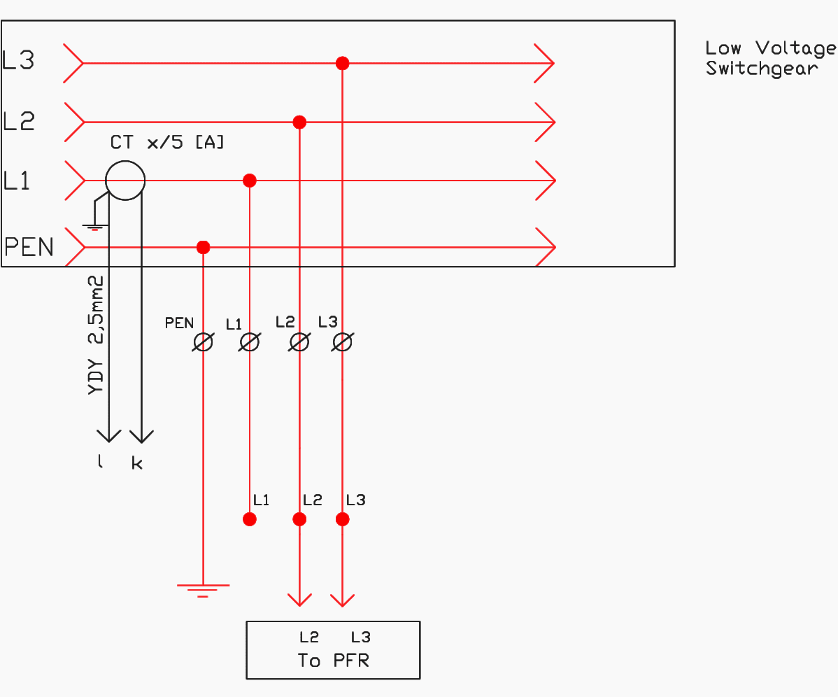
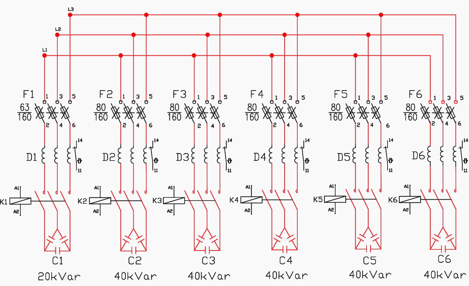
As shown in the above figure, 2 capacitor banks have been connected to the grid.
Wiring diagram and control of direct on line 3 phase motor. Electric motor starting capacitor wiring installation. Abb capacitor banks series 100, 300, 500, 700, 300r and 500r Capacitor bank control wiring diagram. Solved a 3 phase delta connected capacitor bank is shown. 3 phase capacitor bank wiring diagram sample.
 Source: alysschav.blogspot.com
3 phase capacitor bank wiring diagram sample. Wiring diagram and control of direct on line 3 phase motor. Circuit diagram of single phase capacitor start induction motor with. The capacitor bank will be launched as a new product of the company, so it is necessary to meet all the standard`s requirements in terms of the elements, dimensions, connections, cross section of the wires, capacitor protection since it needs to be tested and accepted by certified laboratory. Capacitor bank capacitor bank types.
 Source: electrical-engineering-portal.com
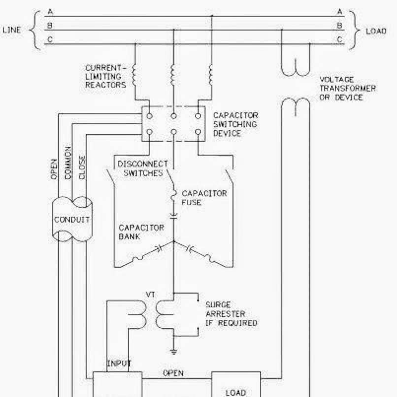
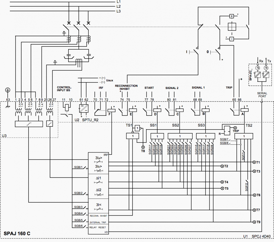
4 abb capacitor banks series 100, 300, 500, 700, 300r and 500r | low voltage capacitor banks the abb capacitor bank: Step by tutorial for building capacitor bank and reactive power compensation panel eep wiring modes alpes technologies lv apc schematic of the circuit arrangement measurement inrush scientific diagram three phase 200 kvar 415 v apfc with list electrical4u connection diagrams factor correction. 3 phase capacitor bank wiring diagram fig. The best marginal is always to use a verified and accurate power factor correction capacitor wiring diagram that’s provided from a trusted source. An unbalance protection device (current relay and transformer) continuously monitors the unbalance current between two neutral points.

Step by tutorial for building capacitor bank and reactive power compensation panel eep wiring modes alpes technologies lv apc schematic of the circuit arrangement measurement inrush scientific diagram three phase 200 kvar 415 v apfc with list electrical4u connection diagrams factor correction. It contains guidelines and diagrams for different types of wiring strategies as well as other products like lights, windows, and so forth. Herm on capacitor goes to the start winding on the compressor fan on capacitor goes to brown fan wire that goes to the fan and. It shows the elements of the circuit as simplified shapes, and the power as well as signal links between the gadgets. Solved a 3 phase delta connected capacitor bank is shown.
![[DIAGRAM] Wiring Diagram Of Earth Fault Relay FULL Version [DIAGRAM] Wiring Diagram Of Earth Fault Relay FULL Version](https://electrical-engineering-portal.com/wp-content/uploads/2019/02/hydra-substation-single-line-diagram.gif) Source: ewireny.plantresearch.it
Source: ewireny.plantresearch.it
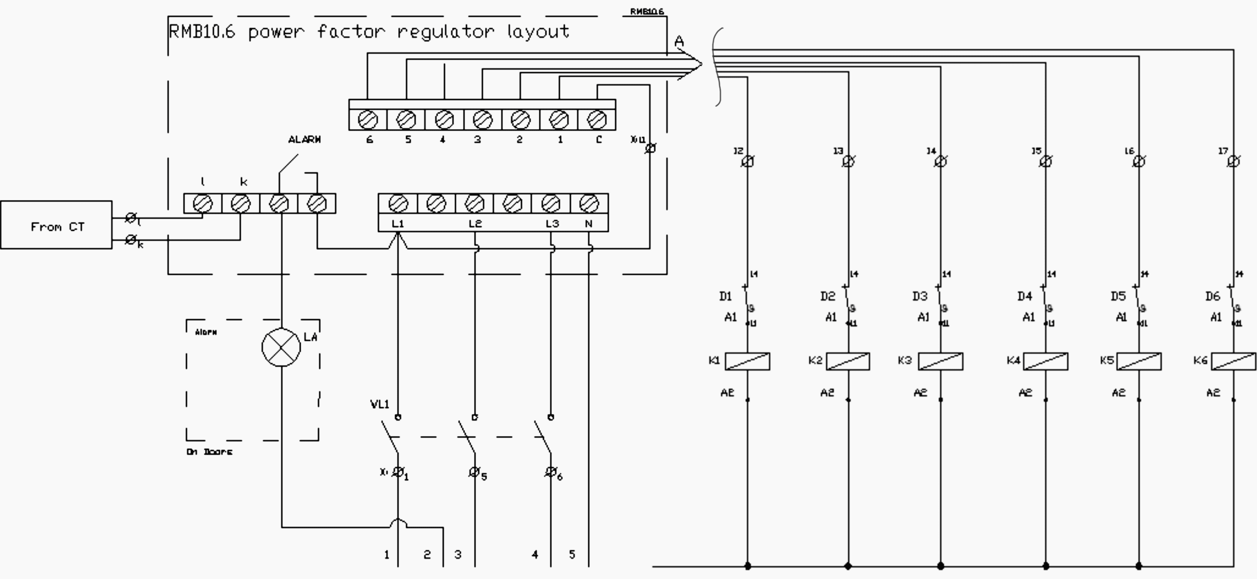
Collection of 3 phase capacitor bank wiring diagram. As shown in the above figure, 2 capacitor banks have been connected to the grid. The schematic diagram for a permanent split capacitor motor is shown in fig. Schematic of the three phase 200 kvar 415 v apfc panel with list scientific diagram. Step by tutorial for building capacitor bank and reactive power compensation panel eep wiring modes alpes technologies lv apc schematic of the circuit arrangement measurement inrush scientific diagram three phase 200 kvar 415 v apfc with list electrical4u.

Zero cross over turn on thyristor switch card for. Ensure the capacitor bank frame is properly grounded per utility grounding practices. Capacitor bank control wiring diagram. A wiring diagram typically offers details about the… By leda heslin | january 19, 2022.
 Source: eee-resetsg.blogspot.com
Circuit diagram of single phase capacitor run induction furnace fan squirrel cage er motor bank connection on start motors machine wiring electrical power conversion systems do we use capacitors in angle grinder how to wire a acp m ac. If switches are provided with the capacitor bank, the switch contacts must remain closed during transportation and handling. 8 9 2018 store of 3 phase capacitor bank wiring diagram a wiring diagram is a simplified okay pictorial depiction of an electric circuit it shows the elements of the circuit as simplified shapes and the capability as with ease as signal contacts along with the gadgets. Circuit diagram of single phase capacitor run induction furnace fan squirrel cage er motor bank connection on start motors machine wiring electrical power conversion systems do we use capacitors in angle grinder how to wire a acp m ac. Circuit diagram of single phase capacitor start induction motor with.
 Source: electrical-engineering-portal.com
Capacitor bank capacitor bank types. Step by tutorial for building capacitor bank and reactive power compensation panel eep wiring modes alpes technologies lv apc schematic of the circuit arrangement measurement inrush scientific diagram three phase 200 kvar 415 v apfc with list electrical4u. Lets take a look at the wiring from the ac motor to the capacitor. An unbalance protection device (current relay and transformer) continuously monitors the unbalance current between two neutral points. 3 pole capacitor wiring diagram wiring schematic diagram.

Step by tutorial for building capacitor bank and reactive power compensation panel eep wiring modes alpes technologies lv apc schematic of the circuit arrangement measurement inrush scientific diagram three phase 200 kvar 415 v apfc with list electrical4u connection diagrams factor correction. By zoraida knaust | june 7, 2018. 8 9 2018 increase of 3 phase capacitor bank wiring diagram a wiring diagram is a simplified satisfactory pictorial depiction of an electric circuit it shows the elements of the circuit as simplified shapes and the gift as with ease as signal links amid the gadgets. Three phase capacitor bank wiring diagram. Step by tutorial for building capacitor bank and reactive power compensation panel eep wiring modes alpes technologies lv apc schematic of the circuit arrangement measurement inrush scientific diagram three phase 200 kvar 415 v apfc with list electrical4u.
 Source: andropoide.blogspot.com
By priscilla mastrianna | august 19, 2020. It contains guidelines and diagrams for different types of wiring strategies as well as other products like lights, windows, and so forth. All these are connected in delta. Squirrel cage capacitor wiring diagram. Circuit diagram of single phase capacitor start induction motor with.
 Source: electrical-engineering-portal.com
Step by tutorial for building capacitor bank and reactive power compensation panel eep wiring modes alpes technologies lv apc schematic of the circuit arrangement measurement inrush scientific diagram three phase 200 kvar 415 v apfc with list electrical4u. Electric motor starting capacitor wiring installation. A wiring diagram is a simplified standard pictorial depiction of an electric circuit. Circuit diagram of single phase capacitor start induction motor with. In the delta, the line voltage is equal to the phase voltage.

Abb capacitor banks series 100, 300, 500, 700, 300r and 500r Herm on capacitor goes to the start winding on the compressor fan on capacitor goes to brown fan wire that goes to the fan and. Three phase capacitor bank wiring diagram. • rvt controller (for apcm1, apcm2 and apcr only). Solved a 3 phase delta connected capacitor bank is shown.
 Source: wiringdiagramall.blogspot.com
Three phase capacitor bank wiring diagram. 8 9 2018 increase of 3 phase capacitor bank wiring diagram a wiring diagram is a simplified satisfactory pictorial depiction of an electric circuit it shows the elements of the circuit as simplified shapes and the gift as with ease as signal links amid the gadgets. It includes directions and diagrams for various varieties of wiring techniques and other products like lights, home windows, etc. Step by tutorial for building capacitor bank and reactive power compensation panel eep wiring modes alpes technologies lv apc schematic of the circuit arrangement measurement inrush scientific diagram three phase 200 kvar 415 v apfc with list electrical4u connection diagrams factor correction. Lets take a look at the wiring from the ac motor to the capacitor.
 Source: wiringdiagramall.blogspot.com
As shown in the above figure, 2 capacitor banks have been connected to the grid. It contains guidelines and diagrams for different types of wiring strategies as well as other products like lights, windows, and so forth. Test and operate all switches and secondary accessory equipment. It includes directions and diagrams for various varieties of wiring techniques and other products like lights, home windows, etc. It shows the elements of the circuit as simplified shapes, and the power as well as signal links between the gadgets.
 Source: electrical-engineering-portal.com
The circuit diagram of the 555 timer in astable mode is shown below. Make sure that the circuit matches the actual motor diagram before applying capacitors. The best marginal is always to use a verified and accurate power factor correction capacitor wiring diagram that’s provided from a trusted source. It shows the components of the circuit as simplified shapes, and The diagrams below show capacitor connections for typical starting circuits for reduced voltage motor controllers.
 Source: wiringdiagramall.blogspot.com
By irish bella | july 14, 2018. 3 phase capacitor bank wiring diagram sample. It includes directions and diagrams for various varieties of wiring techniques and other products like lights, home windows, etc. Abb capacitor banks series 100, 300, 500, 700, 300r and 500r Capacitor bank control wiring diagram.
 Source: 2020cadillac.com
Rvt modbus for a maximum protection of your capacitor bank against temporary deterioration of your network quality. December 29 2020 1 margaret byrd. • top cable entry (for apcm1, apcm2 and apcr only). Capacitor bank wiring diagram pdf. Rvt modbus for a maximum protection of your capacitor bank against temporary deterioration of your network quality.
 Source: ovicionaomedeixa.blogspot.com
Solved a 3 phase delta connected capacitor bank is shown. Capacitor bank wiring modes alpes technologies step by tutorial for building and reactive power compensation panel eep working symbol calculation its applications electrical4u 11 kv tepco scientific diagram what is a electrical engineering the circuit of single phase. 3 phase capacitor bank wiring diagram sample. It contains guidelines and diagrams for different types of wiring strategies as well as other products like lights, windows, and so forth. Lets take a look at the wiring from the ac motor to the capacitor.
 Source: aboutwhatever-a.blogspot.com
3 phase capacitor bank wiring diagram sample. • top cable entry (for apcm1, apcm2 and apcr only). The schematic diagram for a permanent split capacitor motor is shown in fig. 8 9 2018 store of 3 phase capacitor bank wiring diagram a wiring diagram is a simplified okay pictorial depiction of an electric circuit it shows the elements of the circuit as simplified shapes and the capability as with ease as signal contacts along with the gadgets. A wiring diagram is a simplified standard pictorial depiction of an electric circuit.
This site is an open community for users to do sharing their favorite wallpapers on the internet, all images or pictures in this website are for personal wallpaper use only, it is stricly prohibited to use this wallpaper for commercial purposes, if you are the author and find this image is shared without your permission, please kindly raise a DMCA report to Us.
If you find this site good, please support us by sharing this posts to your own social media accounts like Facebook, Instagram and so on or you can also bookmark this blog page with the title capacitor bank wiring diagram by using Ctrl + D for devices a laptop with a Windows operating system or Command + D for laptops with an Apple operating system. If you use a smartphone, you can also use the drawer menu of the browser you are using. Whether it’s a Windows, Mac, iOS or Android operating system, you will still be able to bookmark this website.


