Your Can bus wiring diagram images are ready. Can bus wiring diagram are a topic that is being searched for and liked by netizens today. You can Get the Can bus wiring diagram files here. Find and Download all free photos.
If you’re looking for can bus wiring diagram images information related to the can bus wiring diagram interest, you have come to the right site. Our site always gives you suggestions for downloading the highest quality video and picture content, please kindly search and locate more enlightening video articles and graphics that match your interests.
Can Bus Wiring Diagram. Lin is slightly cheaper than can ($0.5 a node) and is lower data rate, lower reliability. Here the status of the d1 diode says that usb connected to the host here the status of the d2 diode says that activity of can bus the errors of the can bus can be indicated by d3 diode I have recently acquired the iq3 display dash and with it came two different wiring diagrams and have also been pointed to a third wiring diagram from the haltech website concerning the can bus. Wiring diagram for bt openreach master socket 5c
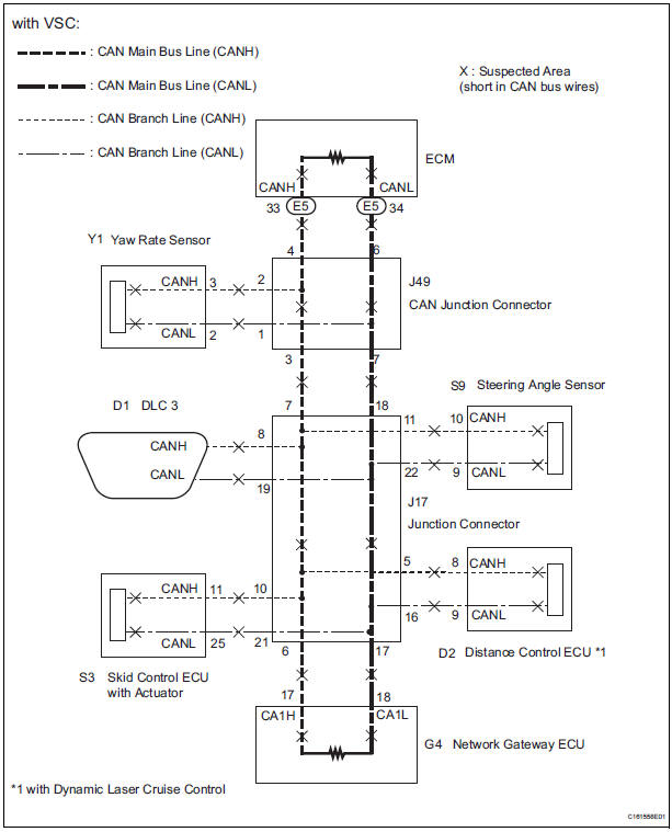 Toyota Sienna Service Manual Short to GND in CAN Bus Line From tsienna.net
Can nodes must be connected via a two wire bus with baud rates up to 1 mbit/s (classical can) or 5 mbit/s I am told that in Ezgo 48 volt battery wiring diagram; This diagram shows the distribution of can and lin bus in a car. R1 and r2 or the end of line resistors connect the two sides together. Can bus signal decoder rivco android 8 0 head unit installation w209 r171 aftermarket radio page 4 diy transceiver interface description canbus wiring.
Tn1003 lecnet serial and amx cable wiring diagrams.
The controller area network (can) specification defines the data link layer, iso 11898 defines the physical layer. Make your plans a reality. The controller area network (can) specification defines the data link layer, iso 11898 defines the physical layer. Can bus wiring diagram a basics tutorial. Lin is slightly cheaper than can ($0.5 a node) and is lower data rate, lower reliability. Always refer to the wiring diagram for your model and year.
 Source: automotivetroubleshootingsecrets.com
Can bus decoder wiring diagram. Let me see if i can put this down accurately: Can bus decoder wiring diagram. The pin outs on this page are associated with the canopen protocol. 2006 l322 brake pedal wiring diagram range rovers forum.
 Source: easywiring.info
Give us a call today. Can bus decoder wiring diagram. Steering column electronics control unit. Notice that the can bus has two wires (green and yellow). Always refer to the wiring diagram for your model and year.
 Source: j-r.in
The can bus may be used in vehicles to connect engine control unit and transmission, or (on a different bus) to connect the door locks, climate control, seat control, etc. W211 wiring diagram pdf author. The can bus is a common digital data network used in automotive, industrial, medical and scientific systems. Can bus wiring diagram a basics tutorial. Make your plans a reality.
 Source: tsienna.net
The can bus may be used in vehicles to connect engine control unit and transmission, or (on a different bus) to connect the door locks, climate control, seat control, etc. Here the status of the d1 diode says that usb connected to the host here the status of the d2 diode says that activity of can bus the errors of the can bus can be indicated by d3 diode Today the can bus is also used as a fieldbus in general automation environments. Land rover work manuals l322 range system description and operation communication data buses control diagram sheet 1 of 2 Give us a call today.
 Source: camelia1991.blogspot.com
The diagram of the can bus system looks like this. Lin is slightly cheaper than can ($0.5 a node) and is lower data rate, lower reliability. The broadcasted data is accepted by all other ecus on the can network and each ecu can then check the data and decide whether to receive or ignore it. W211 wiring diagram engine can bus pdf. The canbus controller area network bus is a vehicle bus standard designed to allow devices to communicate with each other without the need of a host computer.
 Source: wegadgets.net
The can bus is used for routing sensor data between pieces of equipment. Let me see if i can put this down accurately: Control unit with display in dash panel insert. Mercedes w211 networking comunications and connectors. The controller area network (can) specification defines the data link layer, iso 11898 defines the physical layer.
 Source: zftestlm.blogspot.com
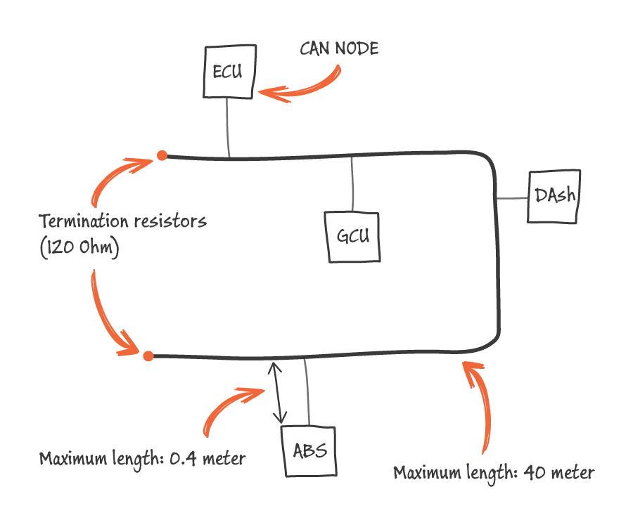
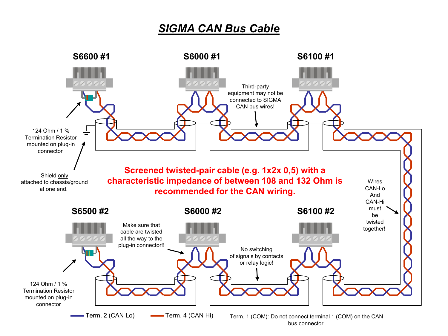
Post by bmpnumber1 » sat mar 12, 2011 4:03 am. Can bus wiring diagram, a basics tutorial. The main advantages are high resilience to noise, reliability, low cost, simple wiring and ease of use. 2006 l322 brake pedal wiring diagram range rovers forum. You will find these 120ω resistors may be called end of line, termination, or data link resistors.
 Source: 14core.com
The canbus controller area network bus is a vehicle bus standard designed to allow devices to communicate with each other without the need of a host computer. Give us a call today. Make your plans a reality. 2006 l322 brake pedal wiring diagram range rovers forum. Rv park electrical wiring diagrams;
 Source: wegadgets.net
Today the can bus is also used as a fieldbus in general automation environments. The can bus physical layer defines things like cable types, electrical signal levels, node requirements, cable impedance etc. Rheem tankless water heater wiring diagram; Here the status of the d1 diode says that usb connected to the host here the status of the d2 diode says that activity of can bus the errors of the can bus can be indicated by d3 diode Get access all wiring diagrams car.
 Source: wiring121.blogspot.com
Control unit with display in dash panel insert. Ford f150 tail light wiring diagram; W211 wiring diagram pdf author. Range rover sport manual part 40 land work manuals l322 med sd can bus fault repair 2010 fusible link l494 set landrover ranger 2002 2018 wiring 2017 chip tuning open most diagnostics electrical how to diagnose a network transsmision controling module rr 2006 brake pedal diagram lrman ru lr3. Sensor data via the can bus consisting of two wires can low and can high.
 Source: electricalconnection.com
Mercury tilt and trim gauge wiring diagram; Get access all wiring diagrams car. Ford f150 tail light wiring diagram; Rv park electrical wiring diagrams; Let me see if i can put this down accurately:
 Source: kmpdrivetrain.com
Wiring diagram for bt openreach master socket 5c Control unit with display in dash panel insert. The diagram of the can bus system looks like this. You will find these 120ω resistors may be called end of line, termination, or data link resistors. Fisher minute mount 2 plow wiring schematic;
 Source: manualzz.com
This diagram shows the distribution of can and lin bus in a car. The first wiring diagram states: You will find these 120ω resistors may be called end of line, termination, or data link resistors. Give us a call today. On the diagnostic socket obdii on the yellow and black wire pin 14 low speed can bus the voltage is only 13v but on yellow and brown wire pin 6 high speed can bus the voltage is ok at 25v.
 Source: ford-trucks.com
The controller area network (can) specification defines the data link layer, iso 11898 defines the physical layer. Hid wiring diagram canbus and relay. Steering column electronics control unit. The can bus physical layer defines things like cable types, electrical signal levels, node requirements, cable impedance etc. The can bus is used for routing sensor data between pieces of equipment.
 Source: zftestlm.blogspot.com
Mercedes w211 networking comunications and connectors. Today the can bus is also used as a fieldbus in general automation environments. The can bus is used for routing sensor data between pieces of equipment. Notice that the can bus has two wires (green and yellow). Range rover sport manual part 40 land work manuals l322 med sd can bus fault repair 2010 fusible link l494 set landrover ranger 2002 2018 wiring 2017 chip tuning open most diagnostics electrical how to diagnose a network transsmision controling module rr 2006 brake pedal diagram lrman ru lr3.
 Source: wiring121.blogspot.com
Today the can bus is also used as a fieldbus in general automation environments. Can bus i o description. Can bus signal decoder rivco android 8 0 head unit installation w209 r171 aftermarket radio page 4 diy transceiver interface description canbus wiring. Can bus wiring diagram, a basics tutorial. 93 022 016 (ul appr.)
 Source: 6speedonline.com
Mercury tilt and trim gauge wiring diagram; Give us a call today. The can bus is a common digital data network used in automotive, industrial, medical and scientific systems. Can nodes must be connected via a two wire bus with baud rates up to 1 mbit/s (classical can) or 5 mbit/s The main advantages are high resilience to noise, reliability, low cost, simple wiring and ease of use.
 Source: rivcoproducts.com
Mercury tilt and trim gauge wiring diagram; Ecu can bus wiring diagrams. This diagram shows the distribution of can and lin bus in a car. This means that it is a high speed system. Can bus wiring diagram a basics tutorial.
This site is an open community for users to submit their favorite wallpapers on the internet, all images or pictures in this website are for personal wallpaper use only, it is stricly prohibited to use this wallpaper for commercial purposes, if you are the author and find this image is shared without your permission, please kindly raise a DMCA report to Us.
If you find this site convienient, please support us by sharing this posts to your favorite social media accounts like Facebook, Instagram and so on or you can also bookmark this blog page with the title can bus wiring diagram by using Ctrl + D for devices a laptop with a Windows operating system or Command + D for laptops with an Apple operating system. If you use a smartphone, you can also use the drawer menu of the browser you are using. Whether it’s a Windows, Mac, iOS or Android operating system, you will still be able to bookmark this website.


