Your Camshaft position sensor wiring diagram images are available in this site. Camshaft position sensor wiring diagram are a topic that is being searched for and liked by netizens now. You can Download the Camshaft position sensor wiring diagram files here. Download all royalty-free vectors.
If you’re looking for camshaft position sensor wiring diagram pictures information linked to the camshaft position sensor wiring diagram topic, you have pay a visit to the right blog. Our website frequently gives you suggestions for viewing the maximum quality video and picture content, please kindly hunt and find more enlightening video articles and images that match your interests.
Camshaft Position Sensor Wiring Diagram. Powertrain control module (pcm) 1. You may be dealing with a wire, connector, or related component failure that you can fix yourself. Crankshaft sensor diagnosis with an ohmmeter. The crankshaft position (ckp) sensor is located on the right lower side of the engine and above the starter motor.
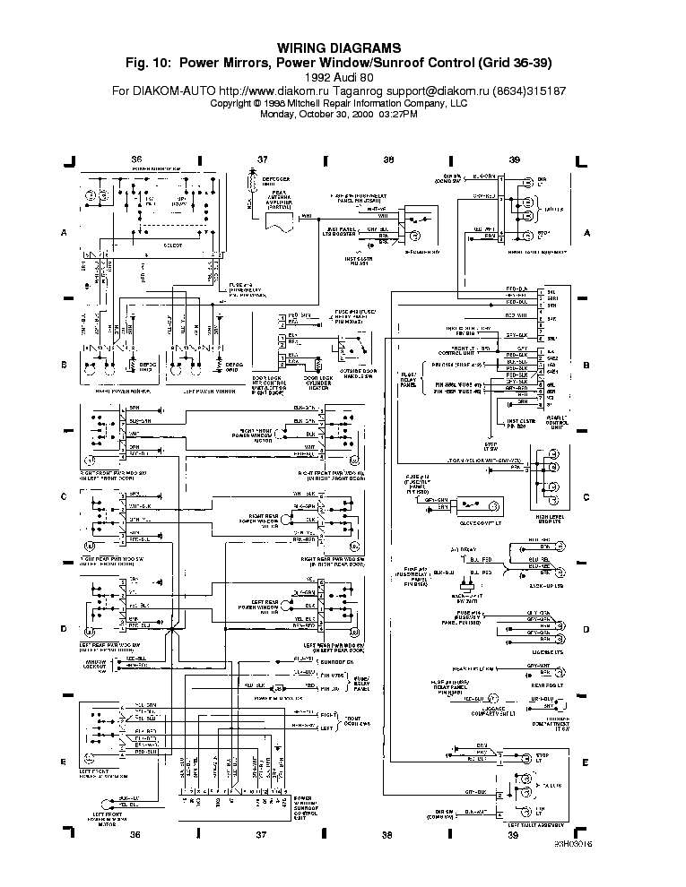
 Schematic") Hyundai Tucson Camshaft Position Sensor (CMPS) Schematic From htmanual.net
Hyundai Tucson Camshaft Position Sensor (CMPS) Schematic From htmanual.net
I need to go back and get it right. Now, move a metal object like a screwdriver or wrench around the sensor in the place where the camshaft would usually be. 1 trick that we 2 to printing a similar wiring plan off twice. I need the wiring diagram for the camshaft position. On the timing chain gear since the camshaft position sensor and jumper harness: The crankshaft position sensor (ckp) measures crankshaft location and relays then, obtain a resistance reading of your crank sensor from a repair manual.
Dodge dakota camshaft position sensor connector wiring print the wiring diagram off plus use highlighters to trace the signal.
The following tutorial will help you to test the camshaft position (cmp) sensor: Ce but then have the camshaft position sensor mounted in the timing cover and. 18.11.2015 · if spikes or glitches are observed, carefully wiggle the wiring harness and connector for the sensor in question to try and determine whether the problem is a loose connection or a defective. In the diagrams down below i have included both the original equipment manufacturer[oem] and non oem wiring diagrams with the wires highlighted for you and the connector pinout for various connectors on your vehicle. 2l chrysler crankshaft sensor wiring diagram ricks free auto repair advice ricks free auto repair advice automotive repair tips and how to from ricksfreeautorepairadvice.com a wiring diagram is a simple visual representation of the. Now, move a metal object like a screwdriver or wrench around the sensor in the place where the camshaft would usually be.
 Source: wiring88.blogspot.com
Crankshaft sensor diagnosis with an ohmmeter. The crankshaft position (ckp) sensor is located on the right lower side of the engine and above the starter motor. It shows the color and position of the wires. The camshaft position sensor sends this signal to the pcm via the signal wire in the wiring harness (see fig. Disconnect the cmp sensor jumper harness (2) and the engine harness (3) electrical connectors.
 Source: crankbydesign.blogspot.com
Looked up in wiring diagrams, but its not working. The crankshaft position (ckp) sensor is located on the right lower side of the engine and above the starter motor. Posted on apr 17, 2011. The second is the ground wire, which is necessary for the current to complete an electrical circuit. Finished putting engine back together, but it won�t start.
 Source: diagramweb.net
This information is required to calculate the ignition point and injection point, among other things. Properly functioning sensor will range from 550 to 750 ohms. You may be dealing with a wire, connector, or related component failure that you can fix yourself. Dodge dakota camshaft position sensor connector wiring print the wiring diagram off plus use highlighters to trace the signal. When the camshaft rotates, each of 3 teeth on the camshaft passes through the cmp sensor.
 Source: autozone.com
Look for any chafed, pierced, pinched, or partially broken wires. It shows the color and position of the wires. Connect the ground of your oscilloscope to the black wire, and the tip to the blue/black wire. Finished putting engine back together, but it won�t start. Hello kriswdorsey, below are pictures of the cam position sensor and the crank position sensor.
 Source: diagramweb.net
The other idea is to look closely at the other sensor connectors and see if the. It rises back to 12 volts when the pin leaves the sensor head. Look for any chafed, pierced, pinched, or partially broken wires. On this page, you can find out how a fault on the camshaft sensor can manifest itself, and which steps should be taken during troubleshooting. This activates the internal magnet in the sensor, generating a voltage in the copper wire.
 Source: schematron.org
When the camshaft timing pin comes close to the sensor head, the voltage at the signal wire drops to zero. On the timing chain gear since the camshaft position sensor and jumper harness: The camshaft sensor enables the engine control to determine the exact position of the crankshaft drive. You may be dealing with a wire, connector, or related component failure that you can fix yourself. Although the car runs fine, it did set code for a camshaft position sensor.
 Source: wiring88.blogspot.com
Schematics and diagrams gmc crankshaft position ckp sensor replacing ignition system circuit diagram 1996 1999 chevy gmc pick up and suv 2001 chevy silverado 1500 5 3 i need a wire diagram for the crank position sensors connector it was pulled off when Look for any chafed, pierced, pinched, or partially broken wires. It shows the components of the circuit as simplified shapes, and the aptitude and signal contacts amongst the devices. Ce but then have the camshaft position sensor mounted in the timing cover and. Properly functioning sensor will range from 550 to 750 ohms.
 Source: justanswer.com
On 2013 ls3 cam position sensor wiring diagram. On 2013 ls3 cam position sensor wiring diagram. 35+ camshaft wiring diagram gif.if your camshaft position sensor fails, how will you know? Crankshaft position sensor wiring harness diagram bmw e90 e91 e92 e93if you need to find the crankshaft position sensor wiring harness and the wire order for. The following tutorial will help you to test the camshaft position (cmp) sensor:
 Source: pro-touring.com
Map sensor adapter extension harness, for ls3 map sensor. I didn�t write down how the cam pos. Crankshaft position sensor wiring diagram. 1 trick that we 2 to printing a similar wiring plan off twice. A wiring diagram makes it easier to check for shorts to ground or power and of course check for continuity between the crank sensor and the pcm.
 Source: crankbydesign.blogspot.com
When you make use of your finger or perhaps the actual circuit with your eyes, it is easy to mistrace the circuit. The wire colors are white, black, and yellow. 18.11.2015 · if spikes or glitches are observed, carefully wiggle the wiring harness and connector for the sensor in question to try and determine whether the problem is a loose connection or a defective. Look for any chafed, pierced, pinched, or partially broken wires. The crankshaft position (ckp) sensor is located on the right lower side of the engine and above the starter motor.
 Source: wiringforums.com
The crankshaft position (ckp) sensor is located on the right lower side of the engine and above the starter motor. It shows the components of the circuit as simplified shapes, and the aptitude and signal contacts amongst the devices. This information is required to calculate the ignition point and injection point, among other things. Powertrain control module (pcm) 1. When you make use of your finger or perhaps the actual circuit with your eyes, it is easy to mistrace the circuit.
 Source: diagramweb.net
When you make use of your finger or perhaps the actual circuit with your eyes, it is easy to mistrace the circuit. When you make use of your finger or perhaps the actual circuit with your eyes, it is easy to mistrace the circuit. The following tutorial will help you to test the camshaft position (cmp) sensor: Crankshaft position sensor wiring diagram. Ce but then have the camshaft position sensor mounted in the timing cover and.
 Source: autozone.com
It rises back to 12 volts when the pin leaves the sensor head. On 2013 ls3 cam position sensor wiring diagram. On honda accord 2.4 crankshaft position sensor wiring diagram. I need to go back and get it right. Connect the ground of your oscilloscope to the black wire, and the tip to the blue/black wire.
 Source: diagramweb.net
A wiring diagram usually gives assistance nearly the relative viewpoint and pact of devices and. I need to go back and get it right. On this page, you can find out how a fault on the camshaft sensor can manifest itself, and which steps should be taken during troubleshooting. Dodge dakota camshaft position sensor connector wiring print the wiring diagram off plus use highlighters to trace the signal. Finished putting engine back together, but it won�t start.
Source: htmanual.net
It shows the color and position of the wires. See attached for the pinout of the camshaft position sensor. A wiring diagram makes it easier to check for shorts to ground or power and of course check for continuity between the crank sensor and the pcm. This is activated by a single vane, and is driven by the camshaft. The camshaft position sensor sends this signal to the pcm via the signal wire in the wiring harness (see fig.
 Source: wiring121.blogspot.com
Map sensor adapter extension harness, for ls3 map sensor. In the oem wiring diagram there will be a number by each wire. Disconnect the cmp sensor jumper harness (2) and the engine harness (3) electrical connectors. It rises back to 12 volts when the pin leaves the sensor head. Now, move a metal object like a screwdriver or wrench around the sensor in the place where the camshaft would usually be.
 Source: researchgate.net
Doesn’t necessarily mean that the sensor is bad. I need the wiring diagram for the camshaft position. Crankshaft position sensor wiring harness diagram bmw e90 e91 e92 e93if you need to find the crankshaft position sensor wiring harness and the wire order for. Disconnect the cmp sensor jumper harness (2) and the engine harness (3) electrical connectors. Look for any chafed, pierced, pinched, or partially broken wires.
 Source: clublexus.com
See attached for the pinout of the camshaft position sensor. This is activated by a single vane, and is driven by the camshaft. The other idea is to look closely at the other sensor connectors and see if the. It is mounted at the end of the intake camshaft (see fig. The second is the ground wire, which is necessary for the current to complete an electrical circuit.
This site is an open community for users to submit their favorite wallpapers on the internet, all images or pictures in this website are for personal wallpaper use only, it is stricly prohibited to use this wallpaper for commercial purposes, if you are the author and find this image is shared without your permission, please kindly raise a DMCA report to Us.
If you find this site convienient, please support us by sharing this posts to your preference social media accounts like Facebook, Instagram and so on or you can also bookmark this blog page with the title camshaft position sensor wiring diagram by using Ctrl + D for devices a laptop with a Windows operating system or Command + D for laptops with an Apple operating system. If you use a smartphone, you can also use the drawer menu of the browser you are using. Whether it’s a Windows, Mac, iOS or Android operating system, you will still be able to bookmark this website.