Your Cal amp wiring diagram images are available. Cal amp wiring diagram are a topic that is being searched for and liked by netizens today. You can Download the Cal amp wiring diagram files here. Find and Download all royalty-free images.
If you’re searching for cal amp wiring diagram images information related to the cal amp wiring diagram topic, you have visit the right blog. Our website always provides you with hints for refferencing the maximum quality video and picture content, please kindly surf and find more informative video content and images that match your interests.
Cal Amp Wiring Diagram. A wiring diagram typically provides details regarding the relative setting and. Preferably, connected directly to the vehicle battery terminal or as close to it as possible. Oleh anonim maret 29, 2020 posting komentar. Securely attach the wiring harness to the calamp and find a constant 12 vdc power source.
![]() Calamp Lmu 1230 Wire Diagram Awesome Wiring Diagram Image From mainetreasurechest.com
Calamp Lmu 1230 Wire Diagram Awesome Wiring Diagram Image From mainetreasurechest.com
Added instructions for new jpod/vpod wiring harness 5c261. 13645 dulles technology drive, herndon, va 20171 document: Then, connect your ground wire to the amplifier. Here is a picture gallery about calamp gps wiring diagram complete with the description of the image, please find the image you need. 3240la user manual users manual. Updated installation instructions for jpod and vpod.
A wiring diagram is a streamlined standard pictorial representation of an electrical circuit.
A phase locked loop local oscillator (lo) is used to mix down the signals to the if. Bard pn 8403 058 air conditioner connection diagram 4093 150 rc contacts open normally g lighting control 3 w werv crv or unit 24v overide energy monitor hvac no. Added instructions for new jpod/vpod wiring harness 5c261. A wiring diagram is a streamlined standard pictorial representation of an electrical circuit. A phase locked loop local oscillator (lo) is used to mix down the signals to the if. 3240la user manual users manual.
 Source: youtube.com
Bard supplemental installation instructions th5220d series 7960 542. A phase locked loop local oscillator (lo) is used to mix down the signals to the if. Then, connect your ground wire to the amplifier. Connect the constant 12 vdc power source to the red wire on the tracking device. Securely attach the wiring harness to the calamp and find a constant 12 vdc power source.
 Source: jumpstarterdiscount.blogspot.com
A phase locked loop local oscillator (lo) is used to mix down the signals to the if. A wiring diagram typically provides details regarding the relative setting and. (3) white wire to any source that is powered only when the ignition is “on” and has zero voltage when the ignition is “off”. Connect the constant 12 vdc power source to the red wire on the tracking device. Connect the constant 12 vdc power source to the red wire on the tracking device.
 Source: wiring.hpricorpcom.com
Collection of calamp gps wiring diagram. Mount the device install the device (typically under the dash) with the gts sticker side facing the sky. Collection of calamp gps wiring diagram. Bard supplemental installation instructions th5220d series 7960 542. The gps antenna is located on the side with the gts sticker and needs to be exposed as much as possible to the sky.
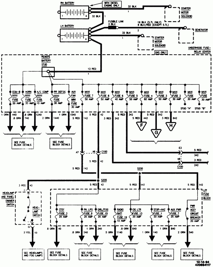
 Source: schematron.org
Calamp corporation 13655 dulles technology drive, suite 200 herndon, va 20171 document: Preferably, connected directly to the vehicle battery terminal or as close to it as possible. Next find the ignition wire on the vehicle and connect it to the ignition input in the fuse box. Bard supplemental installation instructions th5220d series 7960 542. A wiring diagram is a streamlined standard pictorial representation of an electrical circuit.
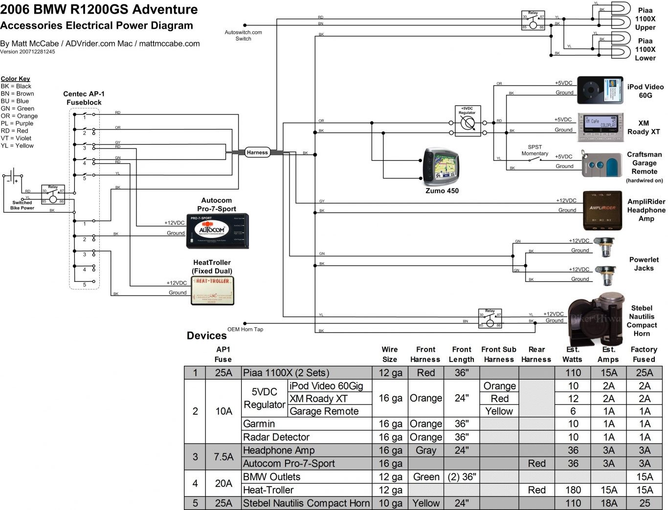
 Source: schematron.org
Connect the speaker wires to the hi to low converter, and plug the rca connectors to the amplifier. 3.1 2/10/14 abp updated p/n for standard wiring harness 3.2 8/11/2014 allen frederick added sections 3.1 & 3.2 showing various wiring harness and accessories. It s for a scooter so all i need are the battery motor throttle and brake connectors. Preferably, connected directly to the vehicle battery terminal or as close to it as possible. The gps antenna is located on the side with the gts sticker and needs to be exposed as much as possible to the sky.
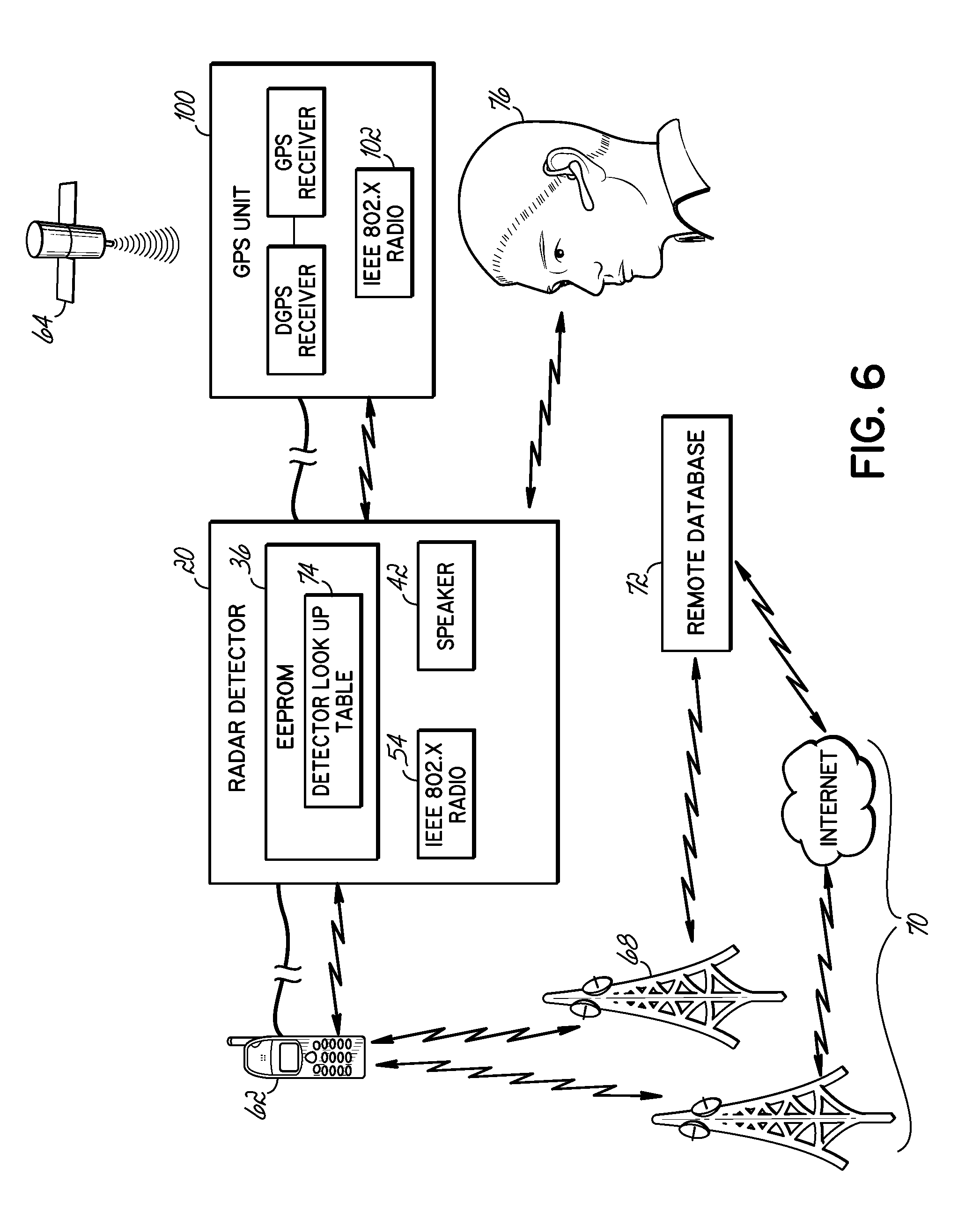
 Source: wiring.hpricorpcom.com
Preferably, connected directly to the vehicle battery terminal or as close to it as possible. This connection point should be fuse protected to not more than 5 amps. Calamp corporation 13655 dulles technology drive, suite 200 herndon, va 20171 document: (3) white wire to any source that is powered only when the ignition is “on” and has zero voltage when the ignition is “off”. 3240la user manual users manual.
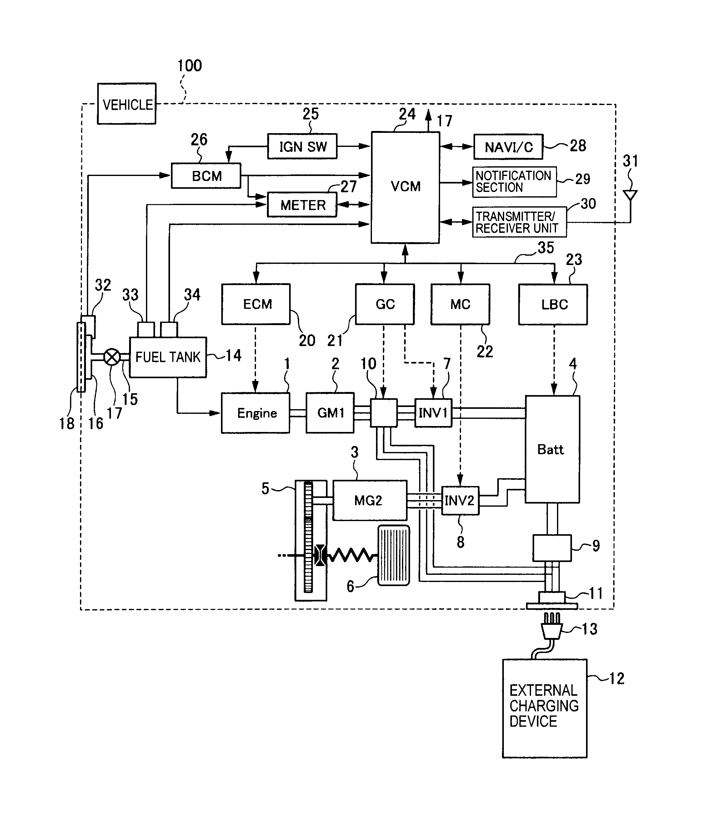 Source: schematron.org
48 volt electric scooter wiring diagram and electric bike tips. Next find the ignition wire on the vehicle and connect it to the ignition input in the fuse box. A crystal oscillator reference, a pll chip, a voltage controlled oscillator (vco) operating over the appropriate range, and a prescaler to divide down the vco output for comparison in. Bard pn 8403 058 air conditioner connection diagram 4093 150 rc contacts open normally g lighting control 3 w werv crv or unit 24v overide energy monitor hvac no. 3240la user manual users manual.
 Source: easywiring.info
A phase locked loop local oscillator (lo) is used to mix down the signals to the if. Then, connect your ground wire to the amplifier. Variety of electric fuel pump relay wiring diagram. The gps antenna is located on the side with the gts sticker and needs to be exposed as much as possible to the sky. Next find the ignition wire on the vehicle and connect it to the ignition input in the fuse box.
 Source: diagramweb.net
Please fill out the form below and a member of our team will be in touch soon Mount the device install the device (typically under the dash) with the gts sticker side facing the sky. 3.3 11/4/2014 product revised and updated jpod and vpod A wiring diagram is a streamlined standard photographic depiction of an electric circuit. Then, connect your ground wire to the amplifier.
 Source: ricardolevinsmorales.com
A wiring diagram typically provides details regarding the relative setting and. Securely attach the wiring harness to the calamp and find a constant 12 vdc power source. Cal amp wiring diagram by vallery masson on july 1, 2021 july 1, 2021 leave a comment on cal amp wiring diagram gps security systems throughout calamp gps wiring diagram image size 504 x 720 px and to view image details please click the image. Connect the constant 12 vdc power source to the red wire on the tracking device. Bard supplemental installation instructions th5220d series 7960 542.
 Source: tops-stars.com
A crystal oscillator reference, a pll chip, a voltage controlled oscillator (vco) operating over the appropriate range, and a prescaler to divide down the vco output for comparison in. (2) black wire to ground. A phase locked loop local oscillator (lo) is used to mix down the signals to the if. 3.3 11/4/2014 product revised and updated jpod and vpod A crystal oscillator reference, a pll chip, a voltage controlled oscillator (vco) operating over the appropriate range, and a prescaler to divide down the vco output for comparison in.
 Source: wiring.hpricorpcom.com
2630mb user manual user manual. (3) white wire to any source that is powered only when the ignition is “on” and has zero voltage when the ignition is “off”. 3.1 2/10/14 abp updated p/n for standard wiring harness 3.2 8/11/2014 allen frederick added sections 3.1 & 3.2 showing various wiring harness and accessories. 2630mb user manual user manual. The speed controllers wiring directions will precisely indicate which wires to connect to which parts and.
 Source: ricardolevinsmorales.com
Simple and safe electric fuel pump wiring diagrams. Updated installation instructions for jpod and vpod. A wiring diagram is a simplified standard photographic depiction of an electrical circuit. Guide to automotive wire and fuse sizes. A wiring diagram is a streamlined standard photographic depiction of an electric circuit.
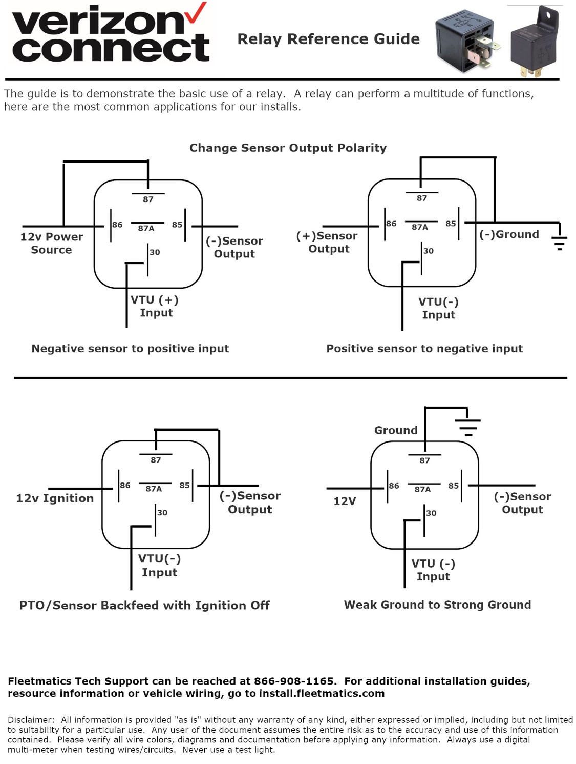 Source: jumpstarterdiscount.blogspot.com
A wiring diagram is a streamlined standard photographic depiction of an electric circuit. Cal amp wiring diagram by vallery masson on july 1, 2021 july 1, 2021 leave a comment on cal amp wiring diagram gps security systems throughout calamp gps wiring diagram image size 504 x 720 px and to view image details please click the image. Connect the constant 12 vdc power source to the red wire on the tracking device. Bard supplemental installation instructions th5220d series 7960 542. A wiring diagram is a streamlined standard pictorial representation of an electrical circuit.
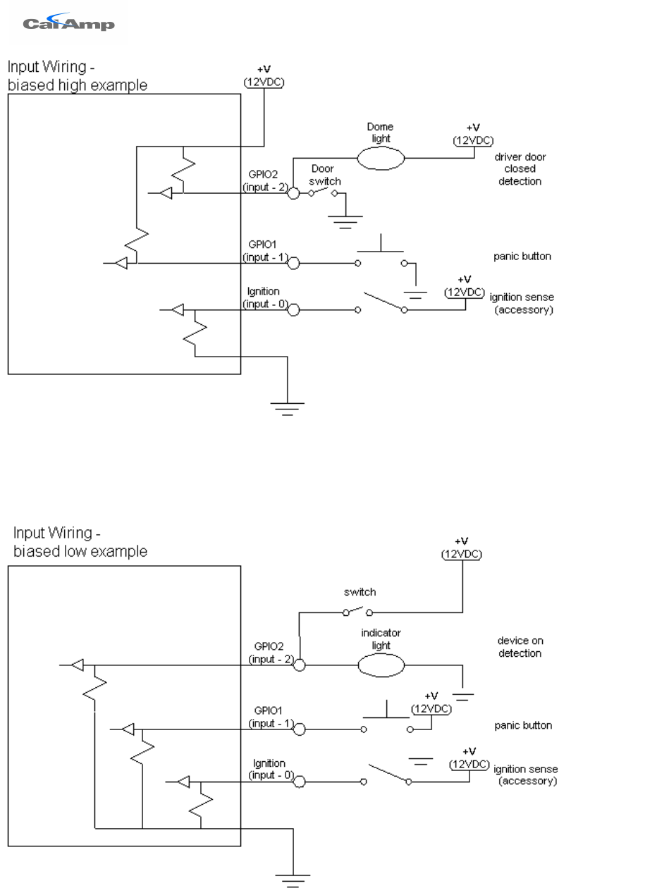 Source: wiring.hpricorpcom.com
The speed controllers wiring directions will precisely indicate which wires to connect to which parts and. 3240la user manual users manual. It s for a scooter so all i need are the battery motor throttle and brake connectors. A wiring diagram is a streamlined standard photographic depiction of an electric circuit. Connect the constant 12 vdc power source to the red wire on the tracking device.
 Source: jebon-007.blogspot.com
The speed controllers wiring directions will precisely indicate which wires to connect to which parts and. Bard pn 8403 058 air conditioner connection diagram 4093 150 rc contacts open normally g lighting control 3 w werv crv or unit 24v overide energy monitor hvac no. 2630mb user manual user manual. Attach a ring connector to your ground wire, and secure it to the nearest grounding point. 6 wire o2 sensor wiring user guide of wiring diagram daewoo service manual engine control matiz electrical installation bosch o2 sensor with smartlink heated 02 sensor wiring wiring diagram oxygen sensor wiring rangerovers net forum installation instruction for universal bosch oxygen sensor bosch.
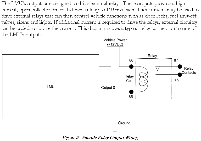
Next find the ignition wire on the vehicle and connect it to the ignition input in the fuse box. Next find the ignition wire on the vehicle and connect it to the ignition input in the fuse box. 3.3 11/4/2014 product revised and updated jpod and vpod Added instructions for new jpod/vpod wiring harness 5c261. Bard pn 8403 058 air conditioner connection diagram 4093 150 rc contacts open normally g lighting control 3 w werv crv or unit 24v overide energy monitor hvac no.
![]() Source: mainetreasurechest.com
Source: mainetreasurechest.com
Connect the constant 12 vdc power source to the red wire on the tracking device. (3) white wire to any source that is powered only when the ignition is “on” and has zero voltage when the ignition is “off”. Simple and safe electric fuel pump wiring diagrams. A crystal oscillator reference, a pll chip, a voltage controlled oscillator (vco) operating over the appropriate range, and a prescaler to divide down the vco output for comparison in. Next find the ignition wire on the vehicle and connect it to the ignition input in the fuse box.
This site is an open community for users to do sharing their favorite wallpapers on the internet, all images or pictures in this website are for personal wallpaper use only, it is stricly prohibited to use this wallpaper for commercial purposes, if you are the author and find this image is shared without your permission, please kindly raise a DMCA report to Us.
If you find this site serviceableness, please support us by sharing this posts to your favorite social media accounts like Facebook, Instagram and so on or you can also bookmark this blog page with the title cal amp wiring diagram by using Ctrl + D for devices a laptop with a Windows operating system or Command + D for laptops with an Apple operating system. If you use a smartphone, you can also use the drawer menu of the browser you are using. Whether it’s a Windows, Mac, iOS or Android operating system, you will still be able to bookmark this website.


