Your Brake force electric brake controller wiring diagram images are ready. Brake force electric brake controller wiring diagram are a topic that is being searched for and liked by netizens today. You can Get the Brake force electric brake controller wiring diagram files here. Download all royalty-free photos.
If you’re looking for brake force electric brake controller wiring diagram pictures information connected with to the brake force electric brake controller wiring diagram keyword, you have pay a visit to the ideal blog. Our website always provides you with hints for seeing the maximum quality video and image content, please kindly surf and locate more enlightening video content and graphics that fit your interests.
Brake Force Electric Brake Controller Wiring Diagram. Prodigy p2 manual pdf •. The 47225 brake control utilizes time based actuation for applying braking power to the trailer brakes. Tow pro classic electric brake controller. Keep these instructions with the brake control for future reference.
 Agility Trailer Brake Controller Wiring Diagram Fantastic From tonetastic.info
Wrg 4423 brake force brake controller wiring diagram. Read the following instructions carefully before January 8, 2022 on rv solar panel installation wiring diagram. All points of tension have been strengthened to ensure that there is a reduced chance of breakage. Hopkins brake controller wiring diagram wiring schematic Of course the one downside is that these systems rely on a sunny day.
827f78 force controller wiring diagram wiring library.
Brake force brake controller wiring diagram by vallery masson on august 11, 2021 auxiliary connection is optional it may be connected to any 12v to 24v constant power source or left unconnected. Schematic diagram of the hydraulic braking system. Count the flashes to determine the current level. Tekonsha voyager wiring diagram 01 96 wiring diagram. Tekonsha voyager wiring diagram wiring diagram. By vallery masson updated on september 5, 2021.
 Source: trailer-wiring-diagram.com
Schematic diagram of the hydraulic braking system. Trailer connector pinout diagrams 4 6 7 pin connectors. Ford trailer brake controller wiring daily update wiring. Features of primus iq brake controller. Tow pro classic electric brake controller.
 Source: bosco-mylove.blogspot.com
Primus™ iq brake control, electronic trailer controls, electrical easy setup instructions. Of course the one downside is that these systems rely on a sunny day. Technical data for e kit electric […] The 47225 brake control utilizes time based actuation for applying braking power to the trailer brakes. Brake controller installation starting from scratch etrailer com trailer control wiring diagram how to install a electric on tow vehicle troubleshooting installations ih8mud forum towing let s talk about controllers 5 easy steps and for.
 Source: 2020cadillac.com
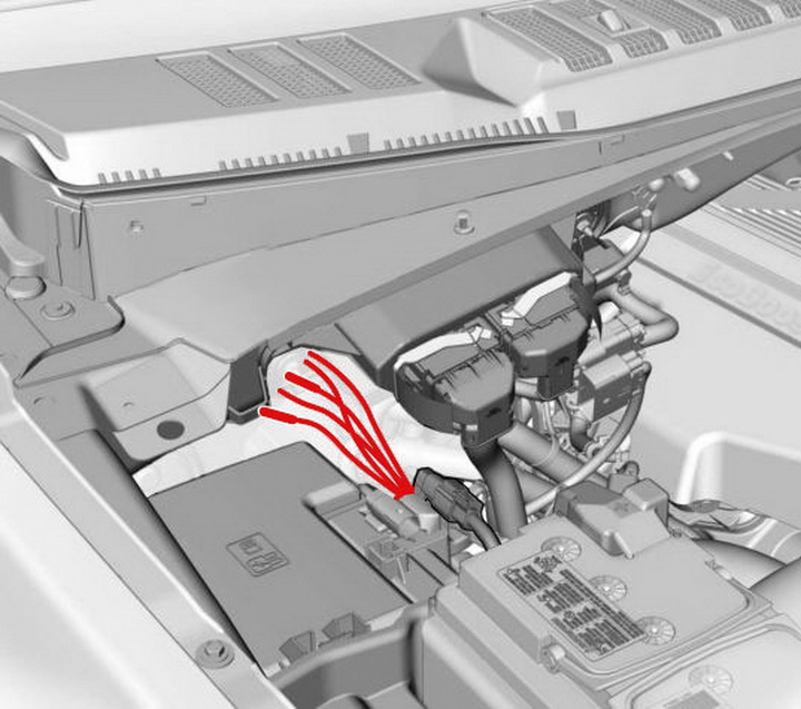
Plug harness into the plug wired to the back of the controller. Ford trailer brake controller wiring daily update wiring. Schematic diagram of the hydraulic braking system. All points of tension have been strengthened to ensure that there is a reduced chance of breakage. Tekonsha voyager wiring diagram 01 96 wiring diagram.
 Source: wiringdiagram.2bitboer.com
An led indicator will glow displaying braking intensity. Technical data for e kit electric […] However, it does not mean connection between the cables. The brighter the glow, the more braking force is being applied to the trailer brakes. Wiring diagram for brake force controller.
 Source: teisco-wiring-diagram88.blogspot.com
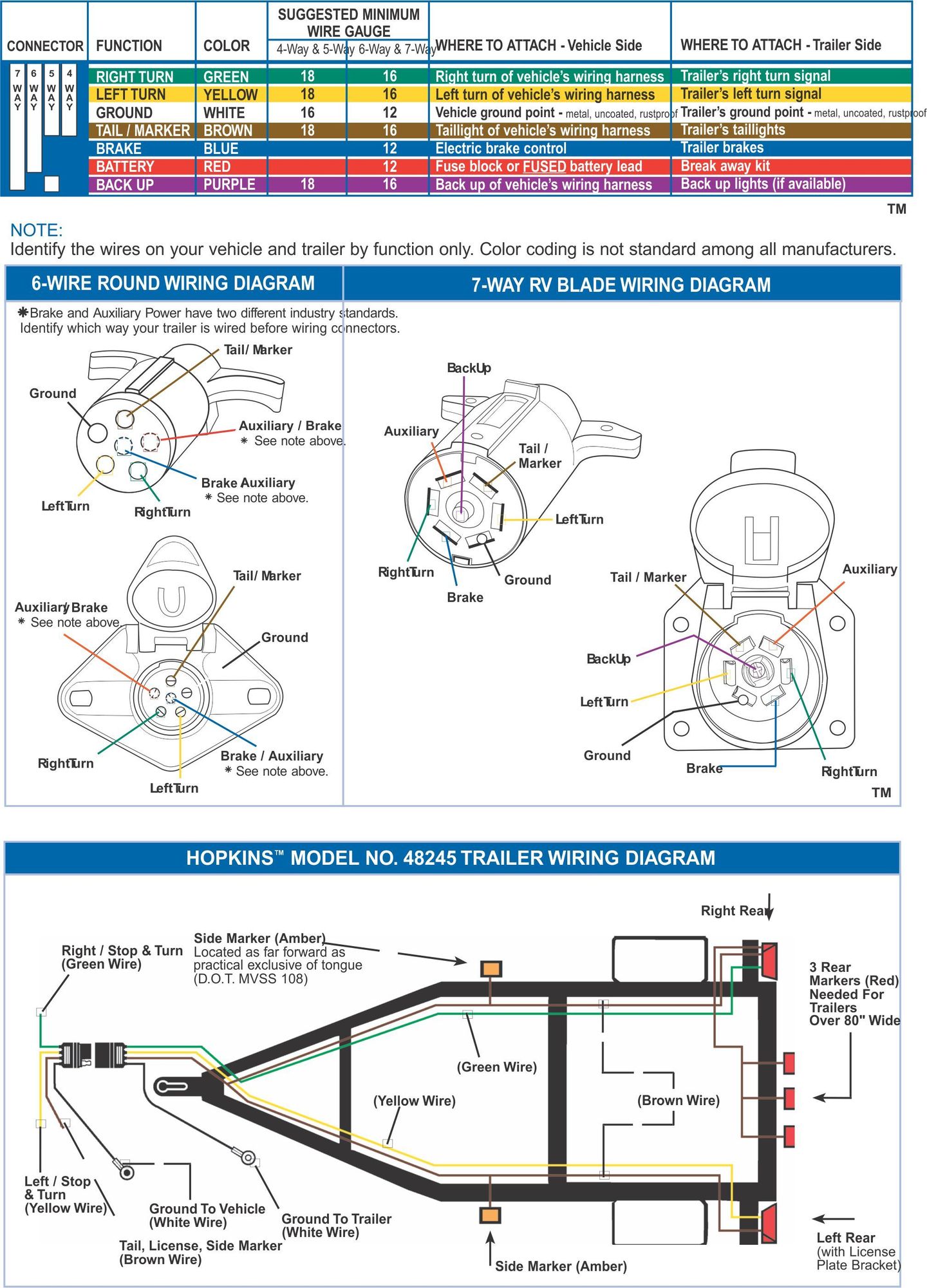
The 47225 brake control utilizes time based actuation for applying braking power to the trailer brakes. Trailer wiring diagrams trailer wiring connectors various connectors are available from four to seven pins that allow for the transfer of power for the lighting as well as auxiliary functions such as an electric trailer brake controller, backup lights, or a 12v power supply for a winch or interior trailer lights. I have a 16 ft jayco starcraft caravan with electric brakes.i have fitted a tekonsha primus iq brake controller to my tow vehicle.the controller is showing that there is a short in the wiring.on unplugging brake magnets the wiring is clear.each magnet is measuring 3.4 ohms and testing from the tow plug the measurement is 1.7 ohm.the brakes are. Read the following instructions carefully before Plug harness into the plug wired to the back of the controller.
 Source: trailer-wiring-diagram.com
Most states and provinces require a trailer brake controller based on the weight of the trailer. Break away systems may be added to the service brake circuit. Please see “vehicle specific instructions” and “special notes” before every installation. Count the flashes to determine the current level. The service brake circuit must be disconnected from an existing trailer plug.
 Source: tonetastic.info
Brake controller installation starting from scratch etrailer com trailer control wiring diagram how to install a electric on tow vehicle troubleshooting installations ih8mud forum towing let s talk about controllers 5 easy steps and for. The black wire is the power supply line to the brake control. September 5, 2021 on brake force electric brake controller wiring diagram. All points of tension have been strengthened to ensure that there is a reduced chance of breakage. Auxiliary connection is optional, it may be connected to any 12v to 24v constant power source or left unconnected.
 Source: tonetastic.info
The brake control must be installed with a 12 volt negative ground. Newark, delaware 19713 sales & support:. Brake force brake controller wiring diagram by vallery masson on august 11, 2021 auxiliary connection is optional it may be connected to any 12v to 24v constant power source or left unconnected. Brake force brake controller wiring diagram.on the trailer will damage the brake control. Rv solar panel installation wiring diagram.
 Source: tonetastic.info
The service brake circuit must be disconnected from an existing trailer plug. The service brake circuit must be disconnected from an existing trailer plug. Hopkins brake controller wiring diagram wiring schematic Count the flashes to determine the current level. Route blue wire from brake control to vehicle side trailer connector.
 Source: trailer-wiring-diagram.com
Injunction of two wires is generally indicated by black dot on the junction of two lines. The service brake circuit must be disconnected from an existing trailer plug. The red (stoplight) wire must be connected to the cold side of the brake pedal stoplight switch. However, it does not mean connection between the cables. Brake force brake controller wiring diagram.on the trailer will damage the brake control.
 Source: trailer-wiring-diagram.com
Splice the brake control module’s red wire to light green wire using a wire tap. Keep these instructions with the brake control for future reference. January 8, 2022 on rv solar panel installation wiring diagram. Brake force brake controller wiring diagram by vallery masson on august 11, 2021 auxiliary connection is optional it may be connected to any 12v to 24v constant power source or left unconnected. The black wire is the power supply line to the brake control.
 Source: icafasfion.blogspot.com
Of course the one downside is that these systems rely on a sunny day. Plug harness into the plug wired to the back of the controller. Prodigy p2 manual pdf •. Splice the brake control module’s red wire to light green wire using a wire tap. However, it does not mean connection between the cables.
 Source: tonetastic.info
The 2000 grand cherokee in that video did have a factory 7 way so some of the wiring needed for a brake controller was already. However, it does not mean connection between the cables. I have a 16 ft jayco starcraft caravan with electric brakes.i have fitted a tekonsha primus iq brake controller to my tow vehicle.the controller is showing that there is a short in the wiring.on unplugging brake magnets the wiring is clear.each magnet is measuring 3.4 ohms and testing from the tow plug the measurement is 1.7 ohm.the brakes are. The brake control must be installed with a 12 volt negative ground. Most states and provinces require a trailer brake controller based on the weight of the trailer.
 Source: 2020cadillac.com
Wiring diagram for brake force controller. An led indicator will glow displaying braking intensity. The brake forcetm came equipped with a quick connector plug wired to the back of the controller. September 5, 2021 on brake force electric brake controller wiring diagram. These diagrams are designed to be understood by a beginner for a safe and effective install with readily accessible components.
 Source: championtrailers.com
If braking force level is too strong use the down button on the key fob instead of the up button. 0a49f252 3761 4024 b8cd e3fa58e4f6c2 on brake force brake controller wiring diagram force brake house wiring the black wire is the power supply line to the brake control. I have a 16 ft jayco starcraft caravan with electric brakes.i have fitted a tekonsha primus iq brake controller to my tow vehicle.the controller is showing that there is a short in the wiring.on unplugging brake magnets the wiring is clear.each magnet is measuring 3.4 ohms and testing from the tow plug the measurement is 1.7 ohm.the brakes are. You must read and understand the user guide before using the product. September 5, 2021 on brake force electric brake controller wiring diagram.
Source: tonetastic.info
You must read and understand the user guide before using the product. Otherwise, the structure won’t function as it ought to be. Technical data for e kit electric […] Wrg 4423 brake force brake controller wiring diagram. 827f78 force controller wiring diagram wiring library.
 Source: tonetastic.info
Tow pro classic electric brake controller. Otherwise, the structure won’t function as it ought to be. September 5, 2021 on brake force electric brake controller wiring diagram. Each component should be set and linked to different parts in specific way. The brake forcetm came equipped with a quick connector plug wired to the back of the controller.
 Source: tonetastic.info
Route blue wire from brake control to vehicle side trailer connector. The black wire is the power supply line to the brake control. Brake force brake controller wiring diagram by vallery masson on august 11, 2021 auxiliary connection is optional it may be connected to any 12v to 24v constant power source or left unconnected. Brake controller installation starting from scratch etrailer com trailer control wiring diagram how to install a electric on tow vehicle troubleshooting installations ih8mud forum towing let s talk about controllers 5 easy steps and for. Splice the brake control module’s red wire to light green wire using a wire tap.
This site is an open community for users to do submittion their favorite wallpapers on the internet, all images or pictures in this website are for personal wallpaper use only, it is stricly prohibited to use this wallpaper for commercial purposes, if you are the author and find this image is shared without your permission, please kindly raise a DMCA report to Us.
If you find this site helpful, please support us by sharing this posts to your own social media accounts like Facebook, Instagram and so on or you can also save this blog page with the title brake force electric brake controller wiring diagram by using Ctrl + D for devices a laptop with a Windows operating system or Command + D for laptops with an Apple operating system. If you use a smartphone, you can also use the drawer menu of the browser you are using. Whether it’s a Windows, Mac, iOS or Android operating system, you will still be able to bookmark this website.