Your Boss rt3 v plow wiring diagram images are available. Boss rt3 v plow wiring diagram are a topic that is being searched for and liked by netizens now. You can Get the Boss rt3 v plow wiring diagram files here. Get all free vectors.
If you’re searching for boss rt3 v plow wiring diagram images information linked to the boss rt3 v plow wiring diagram keyword, you have come to the ideal site. Our site frequently provides you with hints for seeking the highest quality video and image content, please kindly hunt and locate more enlightening video articles and graphics that fit your interests.
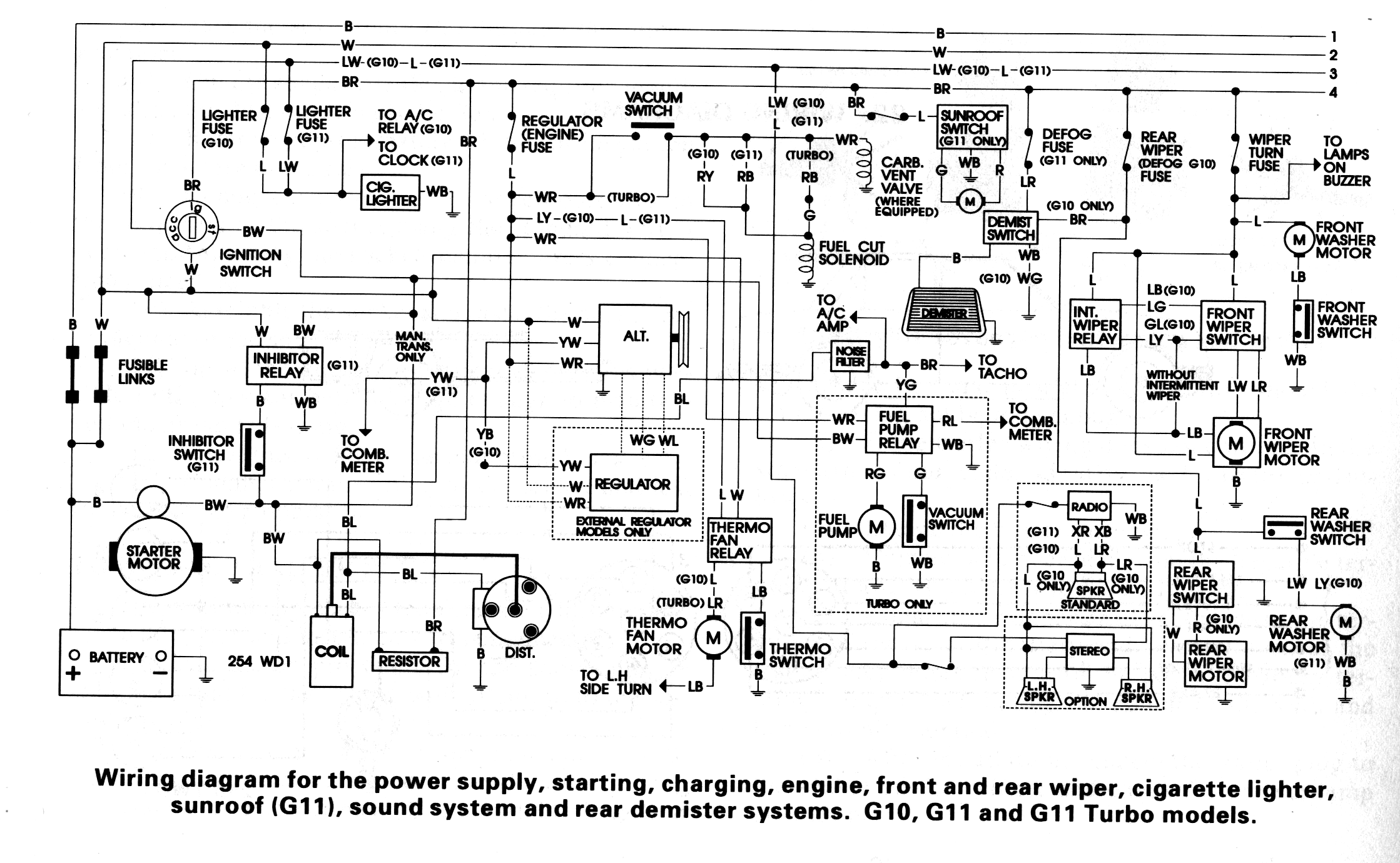
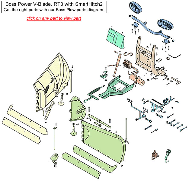
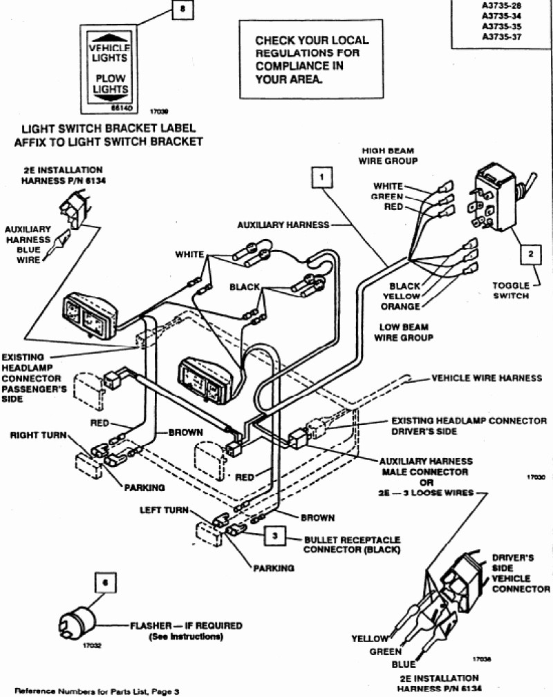
Boss Rt3 V Plow Wiring Diagram. Vehicles equipped with air bags are designed such that the air bags will be activated in a frontal collision equivalent to hitting a solid barrier (such as a wall) at approximately 14 mph or more, or,. It consists of instructions and diagrams for different varieties of wiring methods along with other items like lights, windows, and so forth. Hyd07044 with smarthitch2tm wiring diagram on page 18 of this manual. It all rides on circuit thats being constructed.
 Wiring Diagram Info 22 Boss Plow Wiring Diagram From whatmindsaid.blogspot.com
It really is intended to help all of the common person in creating a correct program. Boss rt3 v plow wiring diagram from www.untpikapps.com. Plows, a boss plow will stand up to severe plowing conditions. These directions will probably be easy to comprehend and use. Begin the assembly procedure by cutting down each corner of the plow box so that each wall of the box will lie flat on the floor. Boss snow plow wiring diagram.
Boss snow plow wiring diagram.
If not, the structure will not work as it should be. It really is intended to assist all of the common consumer in developing a correct method. Sometimes the cables will cross. Each component should be placed and linked to different parts in particular. Each component should be set and connected with different parts in particular way. Electrical system wiring schematic (truck side) electrical system wiring schematic (truck side) g10272.
 Source: schematron.org
To keep your boss plow in top shape, take a few minutes to study this manual. Each component should be set and connected with different parts in particular way…. It really is intended to assist all of the common consumer in developing a correct method. Recommended vehicle models refer to the boss snowplow application chart and selection guide. 7 gray black plow high beam.
![[DIAGRAM in Pictures Database] Wiring Diagram For A Boss V [DIAGRAM in Pictures Database] Wiring Diagram For A Boss V](https://faceitsalon.com/wp-content/uploads/2018/07/the-boss-snow-plow-wiring-diagram-simple-wiring-diagram-for-boss-snow-plow-boss-plow-wiring-diagram-v-boss-v-plow-wire-harness-installation-boss-snow-plow-wiring-harness-18d.jpg) Source: online.casalamm.edu.mx
Source: online.casalamm.edu.mx
Wiring diagram consists of numerous detailed illustrations that display the relationship of various products. Wiring schematic wiring schematic g10004. Fisher plow wiring diagram minute mount 2. Boss rt3 v plow wiring diagram from www.untpikapps.com. Insert the unconnected ends of the plow wiring harness into the back of the coupler through the rubber grommet.
Source: galvinconanstuart.blogspot.com
Wiring schematic wiring schematic g10004. Boss rt3 v plow wiring diagram source. Boss rt3 v plow wiring diagram. Boss snow plow 13 pin 5 relay wiring harness truck side msc08001 169 99 picclick. All wires need to be connected.
 Source: ricardolevinsmorales.com
These directions will probably be easy to comprehend and use. These directions will probably be easy to comprehend and use. Disconnect the left and right headlight connector plugs from the left and right vehicle. Hydraulic power unit fill procedure 8 figure 5. The other thing that you will get a circuit diagram could be lines.
 Source: store.besttruckeq.com
All instructions below are illustrated in figure 10. For example , if a module will be powered up also it sends out a signal of 50 percent the voltage and the technician would not know this, he would. Boss snow plow wiring diagram. The boss snowplow has been carefully designed and built for years of carefree. Each component should be placed and linked to different parts in particular.
 Source: clue.clue.juttaeckenbach.de
The other thing that you will get a circuit diagram could be lines. It really is intended to assist all of the common consumer in developing a correct method. Hydraulic power unit fill procedure 8 figure 5. Smith brothers services sealed beam plow light wiring diagram. Electrical system wiring schematic (plow side) g10271.
![[DIAGRAM in Pictures Database] Wiring Diagram For A Boss V [DIAGRAM in Pictures Database] Wiring Diagram For A Boss V](https://diagramweb.net/img/boss-rt3-wiring-diagram-9.gif) Source: online.casalamm.edu.mx
Source: online.casalamm.edu.mx
Rt3 wiring diagram rt3 wiring diagram. Each component should be set and connected with different parts in particular way…. If not, the arrangement won’t work as it ought to be. Hydraulic power unit fill procedure 8 figure 5. Rt3 wiring diagram rt3 wiring diagram.
![[DIAGRAM] Boss Rt3 Snow Wiring Diagram FULL Version HD [DIAGRAM] Boss Rt3 Snow Wiring Diagram FULL Version HD](https://mainetreasurechest.com/wp-content/uploads/2018/06/curtis-sno-pro-3000-wiring-diagram-unique-diagram-hiniker-snow-plow-wiring-diagram-of-curtis-sno-pro-3000-wiring-diagram-1.png) Source: wiringmarinepdf.evalinka.fr
Source: wiringmarinepdf.evalinka.fr
It will show you how to use and service the boss, familiarize you with all of its parts, and give you helpful tips on plowing snow. For example , if a module will be powered up also it sends out a signal of 50 percent the voltage and the technician would not know this, he would. Begin the assembly procedure by cutting down each corner of the plow box so that each wall of the box will lie flat on the floor. It consists of instructions and diagrams for different varieties of wiring methods along with other items like lights, windows, and so forth. Snowplow assembly procedure 4 snowplow assembly procedure note:
 Source: bosco-mylove.blogspot.com
Disconnect the left and right headlight connector plugs from the left and right vehicle. But it doesnt imply connection between the wires. Otherwise, the structure won’t function as it should be. Wiring schematic wiring schematic g10004. Snowplow assembly procedure 4 snowplow assembly procedure note:
 Source: 2020cadillac.com
To keep your boss plow in top shape, take a few minutes to study this manual. The other thing that you will get a circuit diagram could be lines. Vehicles equipped with air bags are designed such that the air bags will be activated in a frontal collision equivalent to hitting a solid barrier (such as a wall) at approximately 14 mph or more, or,. Connect the plow side wiring harness to the hydraulic valve manifold as shown in figure 26. With its simple attaching system, the boss can be attached or removed in.
Source: anthonywebv.blogspot.com
It really is intended to assist all of the common consumer in developing a correct method. A division of mjelectric inc. 10 rt3 straight blade wiring schematic figure 6. All instructions below are illustrated in figure 10. But it doesnt imply connection between the wires.
 Source: diagramweb.net
Boss plow wiring harness diagram wiring diagram line wiring diagram. But it doesnt imply connection between the wires. It really is intended to assist all of the common consumer in developing a correct method. Boss rt3 v plow wiring diagram. (1) quick pin, 7/16 msc01503.
 Source: jumpstarterdiscount.blogspot.com
10 rt3 straight blade wiring schematic figure 6. Begin the assembly procedure by cutting down each corner of the plow box so that each wall of the box will lie flat on the floor. Rt3 wiring diagram rt3 wiring diagram. Wiring diagram comes with several easy to follow wiring diagram instructions. Wiring diagram will come with several easy to adhere to wiring diagram directions.
 Source: wiringdiagram.2bitboer.com
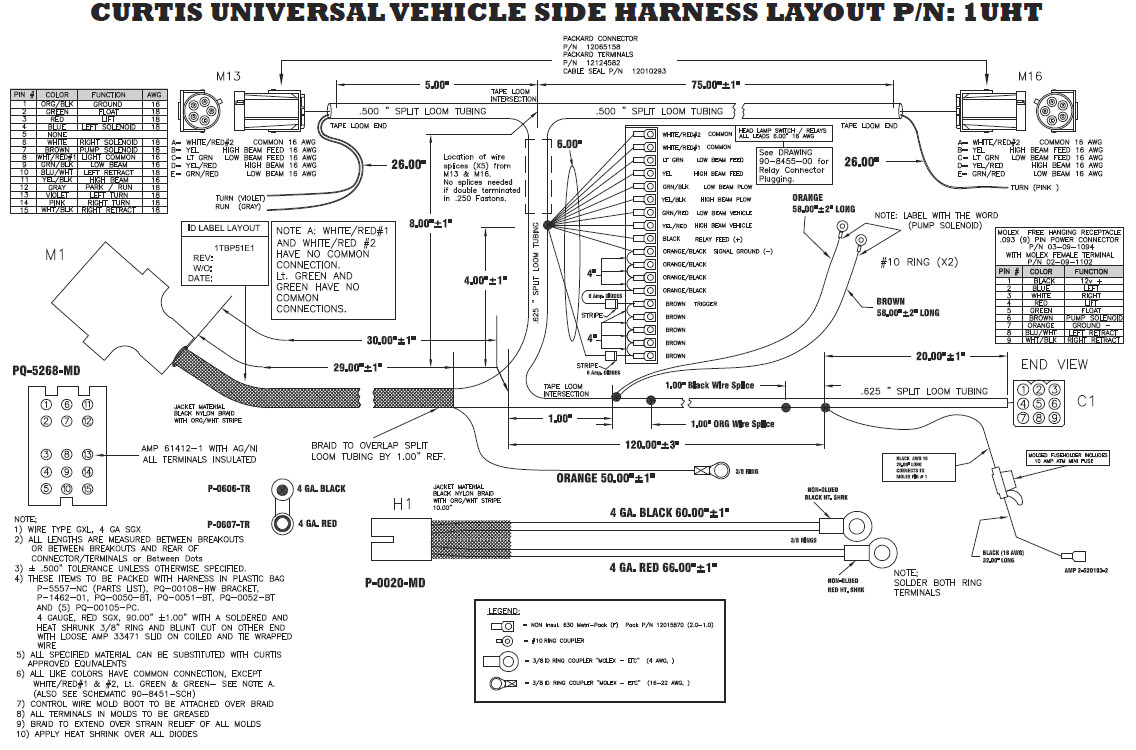
Boss rt3 v plow wiring diagram from www.untpikapps.com. Fisher plow wiring diagram minute mount 2. 10 rt3 straight blade wiring schematic figure 6. Recommended vehicle models refer to the boss snowplow application chart and selection guide. Boss wiring diagram wiring diagram for boss v plow the wiring for boss plow wiring diagram, image size 1103 x 539 px, and to view image details please click the image.
 Source: whatmindsaid.blogspot.com
All wires need to be connected. Western fisher strait blade joystick control 6 pin black. Hyd07044 with smarthitch2tm wiring diagram on page 18 of this manual. Hydraulic power unit fill procedure 8 figure 5. Recommended vehicle models refer to the boss snowplow application chart and selection guide.
 Source: 2020cadillac.com
Electrical system wiring schematic (plow side) g10271. Wiring diagram comes with several easy to follow wiring diagram instructions. Boss vxt v plow parts the boss vxt is built to perform with innovated flared blade wings and enhanced curl design that throws snow higher and farther than conventional plows. Hydraulic power unit fill procedure 8 figure 5. Insert the unconnected ends of the plow wiring harness into the back of the coupler through the rubber grommet.
 Source: anthonywebv.blogspot.com
Boss snow plow wiring diagram. For example , if a module will be powered up also it sends out a signal of 50 percent the voltage and the technician would not know this, he would. To keep your boss plow in top shape, take a few minutes to study this manual. Boss snow plow 13 pin 5 relay wiring harness truck side msc08001 169 99 picclick. Plows, a boss plow will stand up to severe plowing conditions.
Source: turntableab.kinggo.fr
Boss wiring diagram wiring diagram for boss v plow the wiring for boss plow wiring diagram, image size 1103 x 539 px, and to view image details please click the image. Each component should be set and connected with different parts in particular way…. Boss v blade wiring diagram western plow wiring wiring diagram database boss v blade wiring diagram wiring diagram is a simplified customary pictorial. December 25 2020 wiring diagram. Each component should be placed and linked to different parts in particular manner.
This site is an open community for users to do sharing their favorite wallpapers on the internet, all images or pictures in this website are for personal wallpaper use only, it is stricly prohibited to use this wallpaper for commercial purposes, if you are the author and find this image is shared without your permission, please kindly raise a DMCA report to Us.
If you find this site helpful, please support us by sharing this posts to your favorite social media accounts like Facebook, Instagram and so on or you can also bookmark this blog page with the title boss rt3 v plow wiring diagram by using Ctrl + D for devices a laptop with a Windows operating system or Command + D for laptops with an Apple operating system. If you use a smartphone, you can also use the drawer menu of the browser you are using. Whether it’s a Windows, Mac, iOS or Android operating system, you will still be able to bookmark this website.


