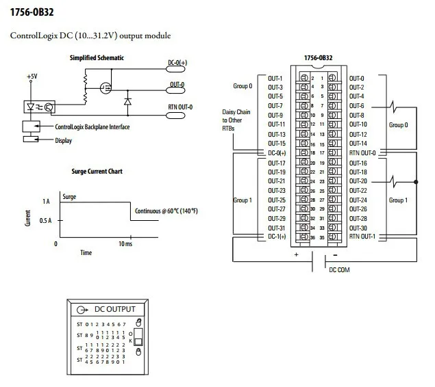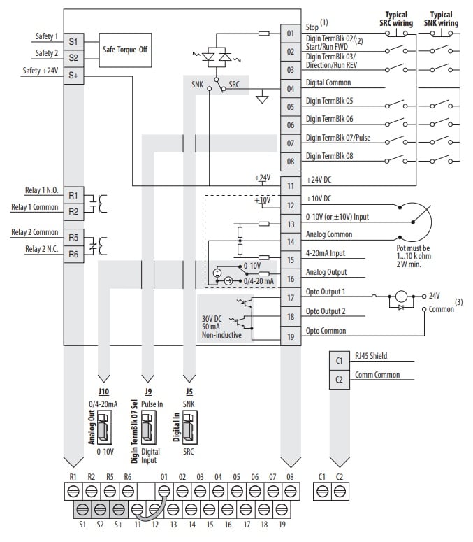
Your Booster pump wiring diagram images are ready in this website. Booster pump wiring diagram are a topic that is being searched for and liked by netizens today. You can Get the Booster pump wiring diagram files here. Get all royalty-free images.
If you’re looking for booster pump wiring diagram pictures information connected with to the booster pump wiring diagram interest, you have come to the ideal site. Our website always gives you hints for viewing the highest quality video and image content, please kindly hunt and locate more enlightening video articles and images that fit your interests.
Booster Pump Wiring Diagram. Buck boost transformer 208 to 230 3 phase wiring diagram. Running the booster pump without the filtration pump will damage the booster pump. Pump can be mounted to the wall horizontally in either direction or vertically only one way ~ with pump head and Here is a quick breakdown on swapping from high v.
 GOULDS BOOSTER PUMPS BUYERS GUIDE From pumpproducts.com
What size circuit breaker do i need for my air conditioner. Attached is the typical grundfos booster pump wiring diagram please check confirm with your own wiring diagrams and electrician. March 31 2018 by headcontrolsystem. If you need advice on product suitability, specification, or installation call us on 023 8066 0122, or chat with us live and our team will answer your questions. Booster pump explain new 2017 youtube well pump refrigeration and. Polaris pb booster pump wiring help yeah forgot to mention i need to wire for high voltage.
Grundfos sl series wiring diagrams pdf seg booster pump tommy o r i e aqqe f a n 98923273 axeon mq user manual instructions up zv diagram for centre guide sqflex renewable energy.
The best way to identify if you pump in new or old style is by looking a the moulding on the front of the pump (volute). Booster pump explain new 2017 youtube well pump refrigeration and. The pb4 has a wavey mould and the older polaris pump has a straight mould (compare images above). It is possible if you put 220 and it was wired for 110 that you may have damaged the motor. What size circuit breaker do i need for my air conditioner. The information provided here is for educational purposes only.
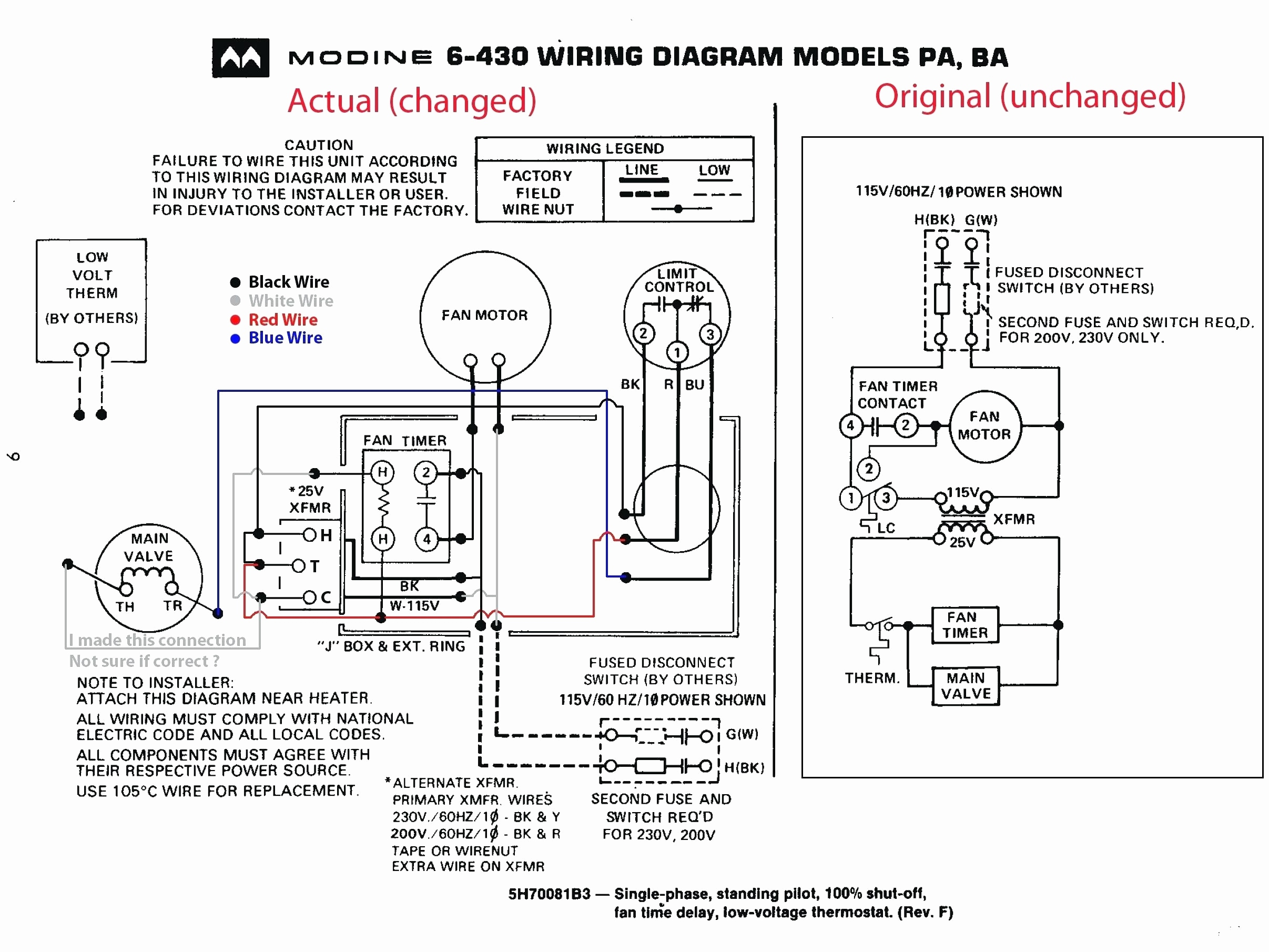 Source: annawiringdiagram.com
The polaris booster pump supplies high pressure water to the booster pump motor is factory wired for cleaner, refer to the typical installation diagram. Install pressure switch in tank line. Polaris pb booster pump wiring help yeah forgot to mention i need to wire for high voltage. Home decorating style 2022 for grundfos booster pump wiring diagram, you can see grundfos booster pump wiring diagram and more pictures for home interior designing 2022 318951 at resume example ideas. Suction lines should have continuous slope upward from lowest point in line.

Hold wrench and turn impellar. The information provided here is for educational purposes only. Wiring diagram panel pompa booster wiring diagram line wiring diagram. March 31 2018 by headcontrolsystem. The booster pump motor is factory wired for cleaner, refer to the typical installation diagram.
![[XR_4992] Wiring Diagram For Brake Booster Wiring Diagram [XR_4992] Wiring Diagram For Brake Booster Wiring Diagram](https://static-cdn.imageservice.cloud/4195022/wiring-a-vacuum-pump-wiring-diagram-library.jpg) Source: exxlu.anth.phae.mohammedshrine.org
Source: exxlu.anth.phae.mohammedshrine.org
I have a new polaris pb booster pump that i bought to replace an pb q, both v old pump had wire diagram for connections. Wiring diagram panel pompa booster wiring diagram line wiring diagram. The polaris booster pump supplies high pressure water to the booster pump motor is factory wired for cleaner, refer to the typical installation diagram. Technically qualified personnel should install pumps and motors. Grundfos booster pump wiring diagram free download 2022 by hans.greenholt.

Wiring diagram line we are make source the schematics, wiring diagrams and technical photos. Improper operation of the booster pump will void the warranty. What size circuit breaker do i need for my air conditioner. Loosen nuts and remove bolts between booster pump volute and seal bracket. Then move white and brown to their proper position depending on your incoming voltage.
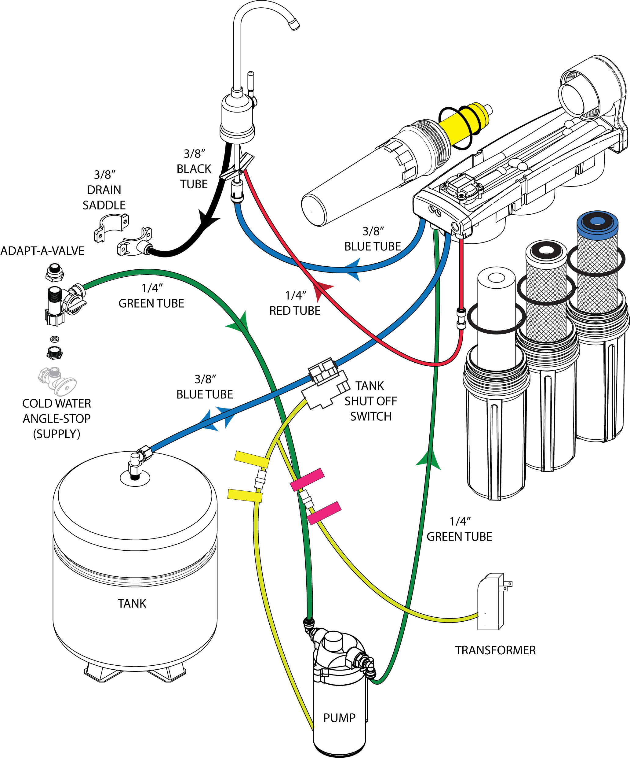 Source: wiringdiagrammechanic.blogspot.com
B) the circuit used for connection must have an 8 to 10 amp fuse! 380v connect pump c.wiring diagram of stable pressure input.vol380v waterpump controller note: Home decorating style 2022 for grundfos booster pump wiring diagram, you can see grundfos booster pump wiring diagram and more pictures for home interior designing 2022 318951 at resume example ideas. Grundfos sl series wiring diagrams pdf seg booster pump tommy o r i e aqqe f a n 98923273 axeon mq user manual instructions up zv diagram for centre guide sqflex renewable energy. Buck boost transformer 208 to 230 3 phase wiring diagram.
 Source: wiringdiagrammechanic.blogspot.com
Here is a quick breakdown on swapping from high v. 380v connect pump c.wiring diagram of stable pressure input.vol380v waterpump controller note: Please make sure switch �pressure /liquid level� to �pressure�, and switch �w ate rfilli n g/ t edrai o wat r filling�. Pump intake connect to vacuum switch to brake booster 5) next, wire the fuse to a positive (+) ignition switched power source. C) make sure to tighten down fuse screws!
 Source: wecofilters.com
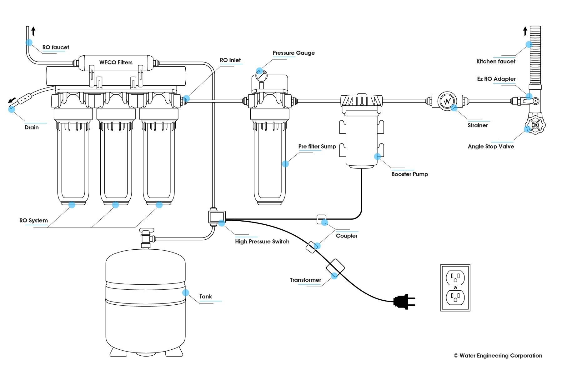
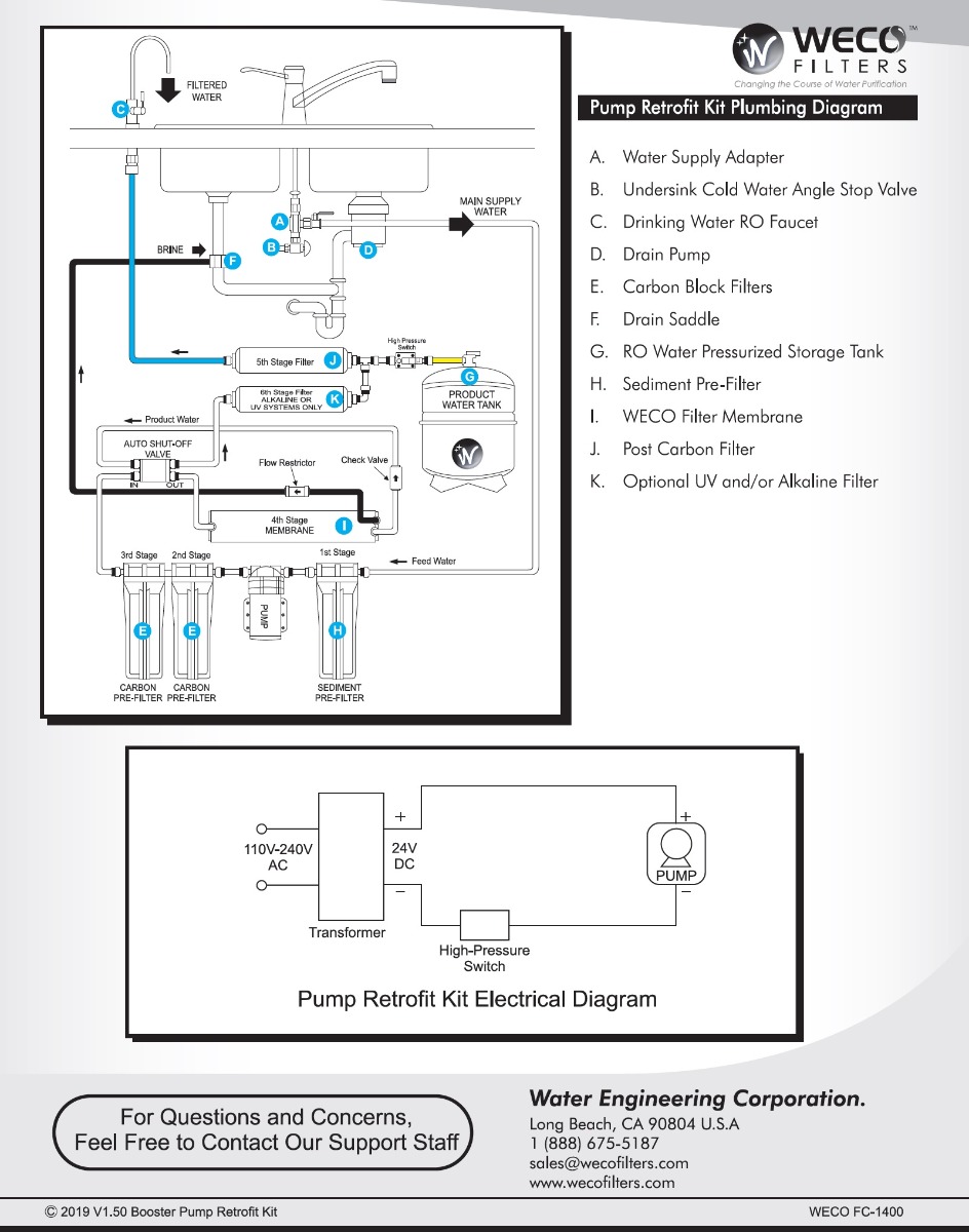
B) the circuit used for connection must have an 8 to 10 amp fuse! The booster pump motor is factory wired for cleaner, refer to the typical installation diagram. Polaris booster pump parts diagram. After guidelines have been met, connect the booster pump wiring to the motor contractor located in the control panel (ref control wiring diagram in the control panel). Locate booster pump as shown in above diagram and run suction lines as direct as possible to reduce friction loss.
 Source: wiringdiagramall.blogspot.com
What size circuit breaker do i need for my air conditioner. Find the besttemplates at vincegray2014. Pump intake connect to vacuum switch to brake booster 5) next, wire the fuse to a positive (+) ignition switched power source. The pb4 has a wavey mould and the older polaris pump has a straight mould (compare images above). The booster pump motor is factory wired for cleaner, refer to the typical installation diagram.
 Source: wiringdiagrammechanic.blogspot.com
The booster pump motor is factory wired for cleaner, refer to the typical installation diagram. Find the besttemplates at vincegray2014. Suction line diameter must equal or be larger than the discharge line diameter. Buck boost transformer 208 to 230 3 phase wiring diagram. March 31 2018 by headcontrolsystem.
 Source: wecofilters.com
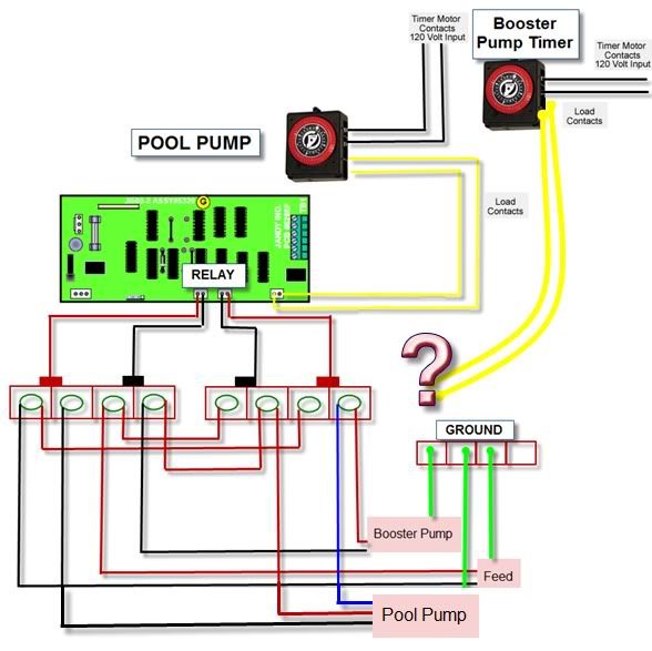
The starting current of the booster pump motor may exceed 15 amps. Pump must be located within 2 feet of pressure switch and within 6 feet of power outlet. Wiring diagram panel pompa booster wiring diagram line wiring diagram. The booster pump motor is factory wired for 240 volts, but can be wired for either 120 or 240 volts. It is possible if you put 220 and it was wired for 110 that you may have damaged the motor.
 Source: terrylove.com
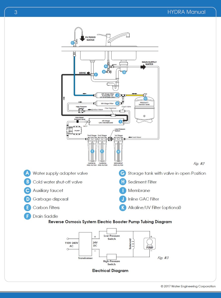
Wiring diagram for well pump pressure switch wiring diagram is a simplified suitable pictorial representation of an electrical circuit. Install pressure switch in tank line. The polaris booster pump supplies high pressure water to the booster pump motor is factory wired for cleaner, refer to the typical installation diagram. I am not sure if this will help you out any, but here goes: Polaris booster pump parts diagram.
 Source: pumpproducts.com
Suction lines should have continuous slope upward from lowest point in line. A) positive (+) connection must be a switched source or pump will run with key off! Please make sure switch �pressure /liquid level� to �pressure�, and switch �w ate rfilli n g/ t edrai o wat r filling�. Buck boost transformer 208 to 230 3 phase wiring diagram. Polaris booster pump parts diagram.
![[DIAGRAM] Piping Diagram For Booster Pump [DIAGRAM] Piping Diagram For Booster Pump](https://cdn.shopify.com/s/files/1/0826/7845/files/Diagram_RO_Pure_Plus_2.png?10395360416090465172_grande.png?12546839895768719691) Source: buffalomountainkombucha.com
Source: buffalomountainkombucha.com
The booster pump motor is factory wired for 240 volts, but can be wired for either 120 or 240 volts. If you are unsure of you incoming voltage you can either disconnect them from. Pump intake connect to vacuum switch to brake booster 5) next, wire the fuse to a positive (+) ignition switched power source. Wiring diagram for well pump pressure switch. The starting current of the booster pump motor may exceed 15 amps.
 Source: troublefreepool.com
Pump can be mounted to the wall horizontally in either direction or vertically only one way ~ with pump head and Wiring diagram line we are make source the schematics, wiring diagrams and technical photos. Jard 3 speed 1 3 hp 208 230 volt direct drive blower motor in 2021 residential furnace natural gas furnace blowers interconnecting cord courses may be shown around where particular receptacles or components have […] 380v connect pump c.wiring diagram of stable pressure input.vol380v waterpump controller note: The pump motor must be securely and adequately grounded using the green screw provided.

Improper operation of the booster pump will void the warranty. (see diagram on back for where to place the pressure switch). The starting current of the booster pump motor may exceed 15 amps. The polaris booster pump supplies high pressure water to the booster pump motor is factory wired for cleaner, refer to the typical installation diagram. Suction lines should have continuous slope upward from lowest point in line.
 Source: mickygurlz.blogspot.com
B) the circuit used for connection must have an 8 to 10 amp fuse! Polaris pb booster pump wiring help yeah forgot to mention i need to wire for high voltage. Attached is the typical grundfos booster pump wiring diagram please check confirm with your own wiring diagrams and electrician. If you need advice on product suitability, specification, or installation call us on 023 8066 0122, or chat with us live and our team will answer your questions. The polaris booster pump supplies high pressure water to the booster pump motor is factory wired for cleaner, refer to the typical installation diagram.
 Source: wiringall.com
The booster pump motor is factory wired for 240 volts, but can be wired for either 120 or 240 volts. Suction lines should have continuous slope upward from lowest point in line. Wiring diagram panel pompa booster wiring diagram line wiring diagram. I am not sure if this will help you out any, but here goes: Grundfos booster pump wiring diagram free download 2022 by hans.greenholt.
 Source: jumpstarterdiscount.blogspot.com
Here is a quick breakdown on swapping from high v. I am not sure if this will help you out any, but here goes: The pump motor must be securely and adequately grounded using the green screw provided. Find the besttemplates at vincegray2014. The information provided here is for educational purposes only.
This site is an open community for users to submit their favorite wallpapers on the internet, all images or pictures in this website are for personal wallpaper use only, it is stricly prohibited to use this wallpaper for commercial purposes, if you are the author and find this image is shared without your permission, please kindly raise a DMCA report to Us.
If you find this site adventageous, please support us by sharing this posts to your preference social media accounts like Facebook, Instagram and so on or you can also bookmark this blog page with the title booster pump wiring diagram by using Ctrl + D for devices a laptop with a Windows operating system or Command + D for laptops with an Apple operating system. If you use a smartphone, you can also use the drawer menu of the browser you are using. Whether it’s a Windows, Mac, iOS or Android operating system, you will still be able to bookmark this website.
