Your Beam detector wiring diagram images are available. Beam detector wiring diagram are a topic that is being searched for and liked by netizens today. You can Find and Download the Beam detector wiring diagram files here. Download all royalty-free images.
If you’re looking for beam detector wiring diagram pictures information related to the beam detector wiring diagram topic, you have pay a visit to the ideal blog. Our website always gives you suggestions for refferencing the maximum quality video and picture content, please kindly surf and find more informative video content and graphics that fit your interests.
Beam Detector Wiring Diagram. The fire beam xtra brochure download. D4120 duct smoke detector the innovairflex series are the only duct smoke detectors flexible enough to. Be sure to connect the power supply wires to terminal 1 and 2. A wiring diagram is a simplified traditional photographic depiction of an electric circuit.
 infrared IR proximity detector/ IR beam barrier circuit From next.gr
A smoke or heat detector can be installed to the existing or new home wiring. Frightprops support dr18 cylinderical photoelectric wiring toy car sd timer adafruit using a break beam sensor with python photoelectric sensor wiring setup and. D4120 duct smoke detector wiring diagram. For us installations it is typically a short circuit. Generic wiring diagram on the following page). The main supply is 120v ac (in us) and 230v ac (in eu).
System sensor model beam/beams is a long range projected beam.
Smoke detectors intercommunicate so that all detectors will sound if one is triggered. For us installations it is typically a short circuit. The beamsmk allows system sensor reflected beam detectors to be mounted when surface wiring is used. Specifications are subject to change without notice. Generic wiring diagram on the following page). The fire beam xtra brochure download.
 Source: wholefoodsonabudget.com
Thefirebeam can easily be made addressable with the use of a manufacturers interface and in some cases can also be powered from the loop, ie with the apollo xp95 switch monitor with isolator. Risk of breaking down the apparatus. Model d4120 and d4s duct smoke detectors utilize 4 wire photoelectric tech nology for the detection of smoke. In our basic wiring diagram, a single or multiple heat and smoke detectors are installed in the home by connecting the live (line or hot), neutral, ground and an interconnected wire to the alarm. Photoelectric beam detectors for access control system and gate opener operator technology news.
 Source: wholefoodsonabudget.com
The beamsmk allows system sensor reflected beam detectors to be mounted when surface wiring is used. Rec eiv r connecting wires to the terminals (normally open wiring). Specifications are subject to change without notice. Risk of breaking down the apparatus. A smoke or heat detector can be installed to the existing or new home wiring.
 Source: burglaryalarmsystem.com
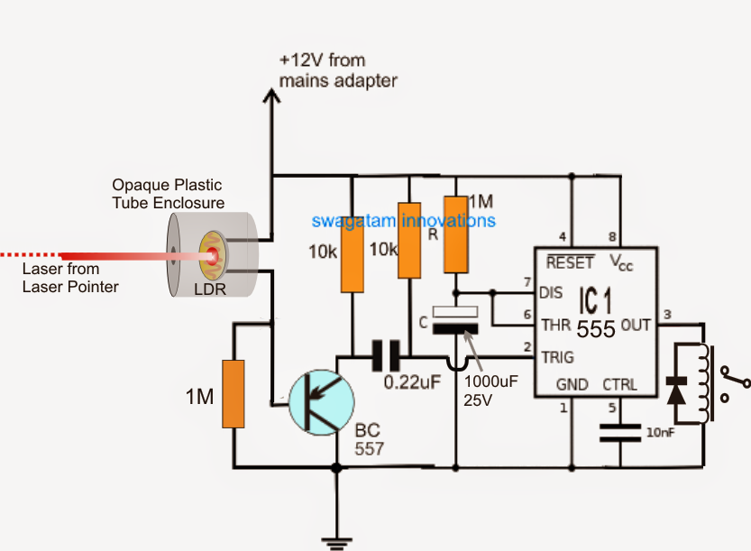
Wire external power to the unit via the power terminals. Parts diagram (not to scale): The main supply is 120v ac (in us) and 230v ac (in eu). Rec eiv r connecting wires to the terminals (normally open wiring). This circuit is mostly used in gardens, so that at night, when we go for a walk in the garden, the circuit switches on a light automatically and it remains lit until we are in the.
 Source: homecontrols.com
The beamsmk allows system sensor reflected beam detectors to be mounted when surface wiring is used. It explains how it works, the features you get as standard, as well as information about our kits and accessories. The beamsmk allows system sensor reflected beam detectors to be mounted when surface wiring is used. Smoke detectors intercommunicate so that all detectors will sound if one is triggered. D4120 duct smoke detector the innovairflex series are the only duct smoke detectors flexible enough to.
 Source: wholefoodsonabudget.com
The receiver is constantly monitoring and measuring the intensity of the beam transmitted by. Parts diagram (not to scale): 15 19 14 3 20 2 11 2 6 alarm signal 1 aux. Thefirebeam can easily be made addressable with the use of a manufacturers interface and in some cases can also be powered from the loop, ie with the apollo xp95 switch monitor with isolator. The fire beam xtra brochure contains detailed information on the range of fire beam products.
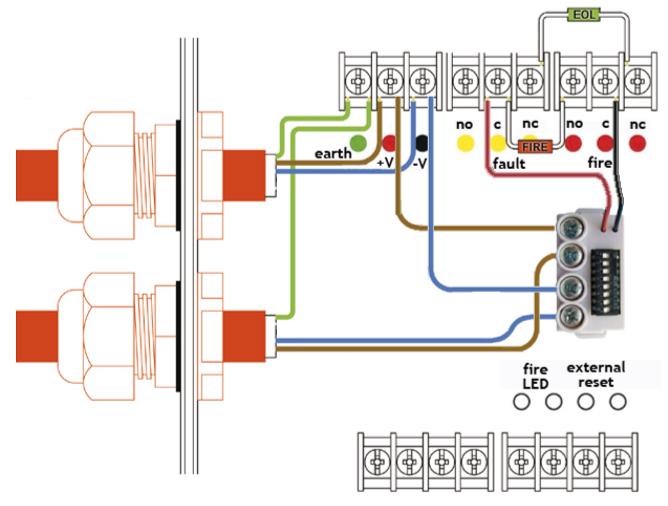 Source: discountfiresupplies.co.uk
For general information, refer to the application guide for projected beam smoke detectors available on request from your supplier. 02.05.2019 · smoke detector spacing with beams and smooth ceilings can be tricky. Ensure that all wiring is below the level of the front edge of the box. It�s a great introduction to the fire beam all inside one pdf document. D4120 duct smoke detector the innovairflex series are the only duct smoke detectors flexible enough to.
 Source: next.gr
For general information, refer to the application guide for projected beam smoke detectors available on request from your supplier. The receiver is constantly monitoring and measuring the intensity of the beam transmitted by. A wiring diagram is a simplified traditional photographic depiction of an electric circuit. Beam smoke detector wiring diagram : The beamsmk allows system sensor reflected beam detectors to be mounted when surface wiring is used.
 Source: pinterest.com
The diagrams below represent the terminal strips on the receiver and transmitter and can be used for reference for connections. A smoke or heat detector can be installed to the existing or new home wiring. Projected beam smoke detector 3825 ohio avenue, st. The beamsmk allows system sensor reflected beam detectors to be mounted when surface wiring is used. A smoke or heat detector can be installed to the existing or new home wiring.
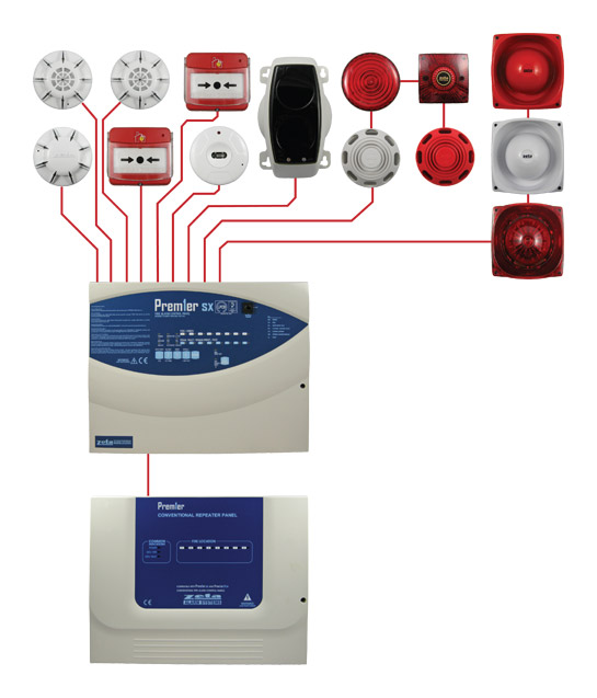 Source: gltexports.com
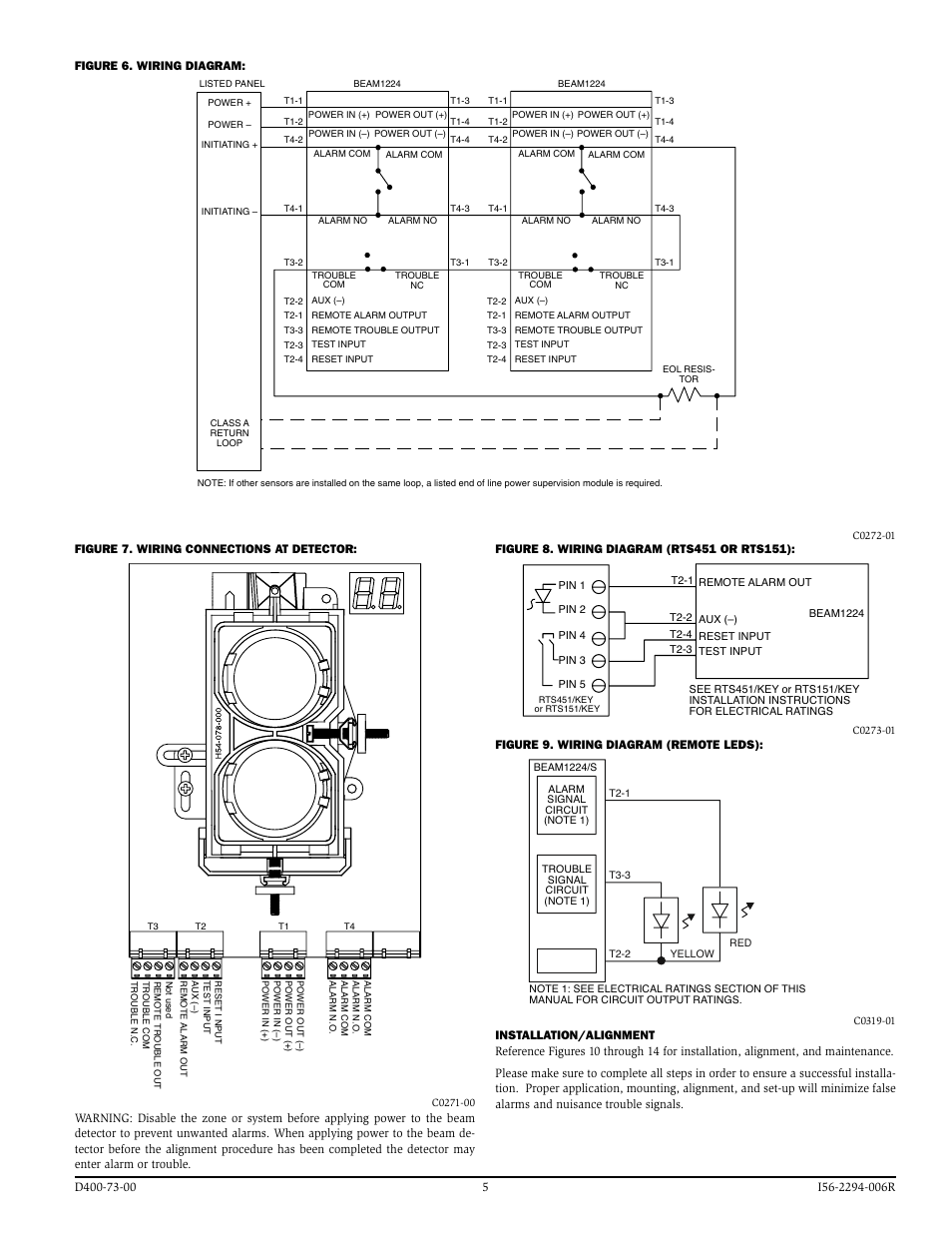
Smoke detectors intercommunicate so that all detectors will sound if one is triggered. Wire external power to the unit via the power terminals. 15 19 14 3 20 2 11 2 6 alarm signal 1 aux. Warning about wiring do not connect more than 2 wires to one terminal. Wiring diagram for connection of a single conventional detector to a zone:
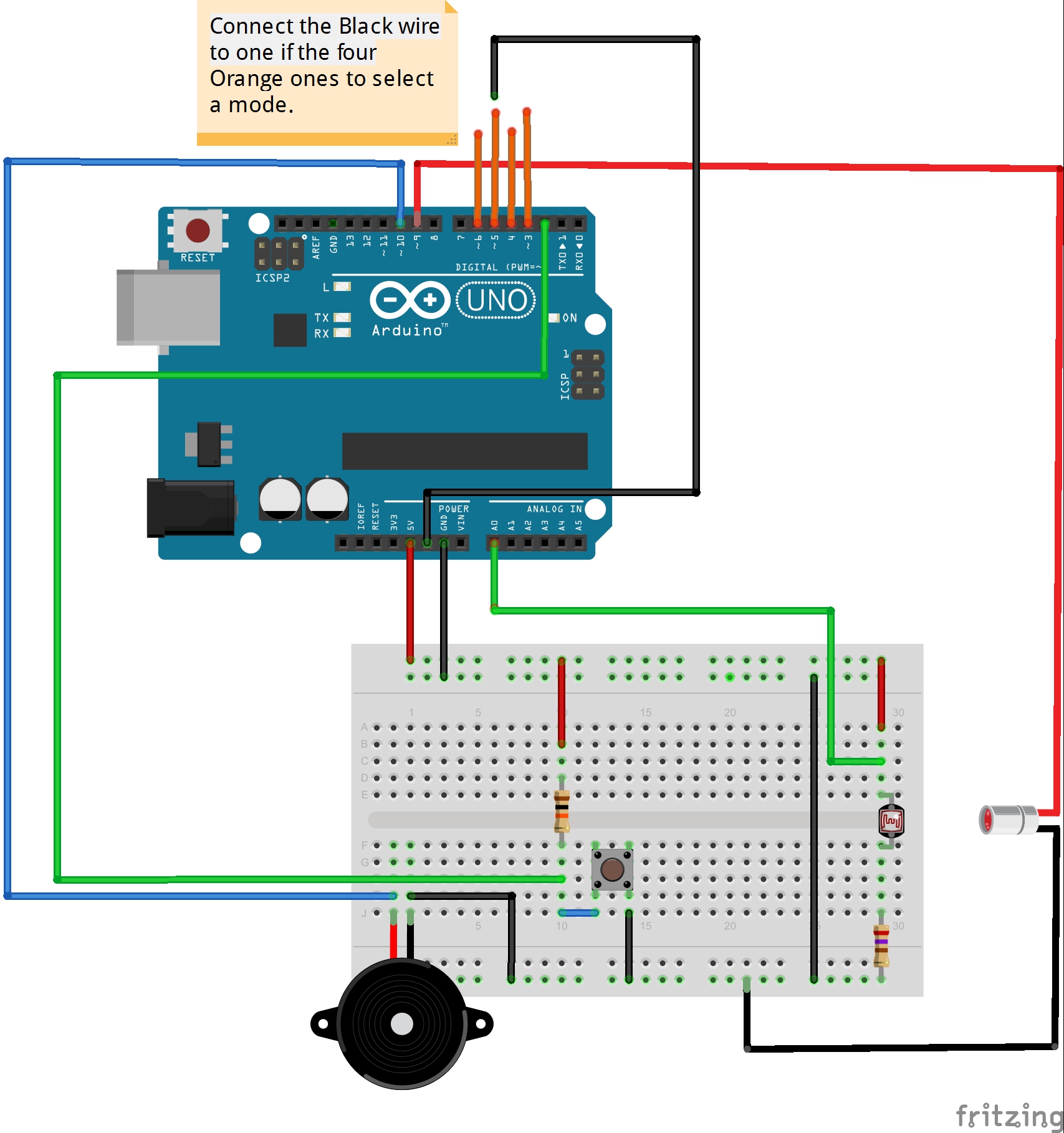 Source: schematron.org
The diagrams below represent the terminal strips on the receiver and transmitter and can be used for reference for connections. Model d4120 and d4s duct smoke detectors utilize 4 wire photoelectric tech nology for the detection of smoke. The installed onto standard two gang electrical box, or directly by drilling the holes and fixing with plugs. Generic wiring diagram on the following page). If wired wrongly, the apparatus may break down.
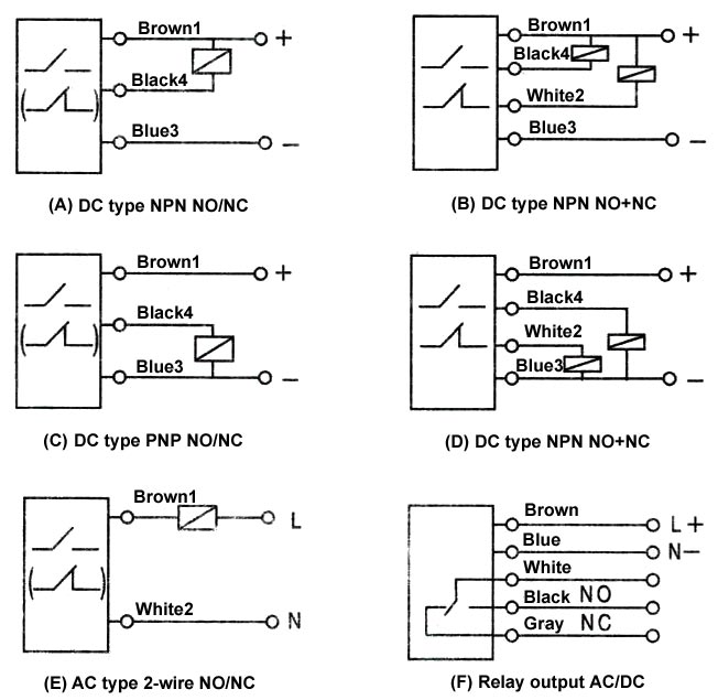 Source: enhancestyleteam.com
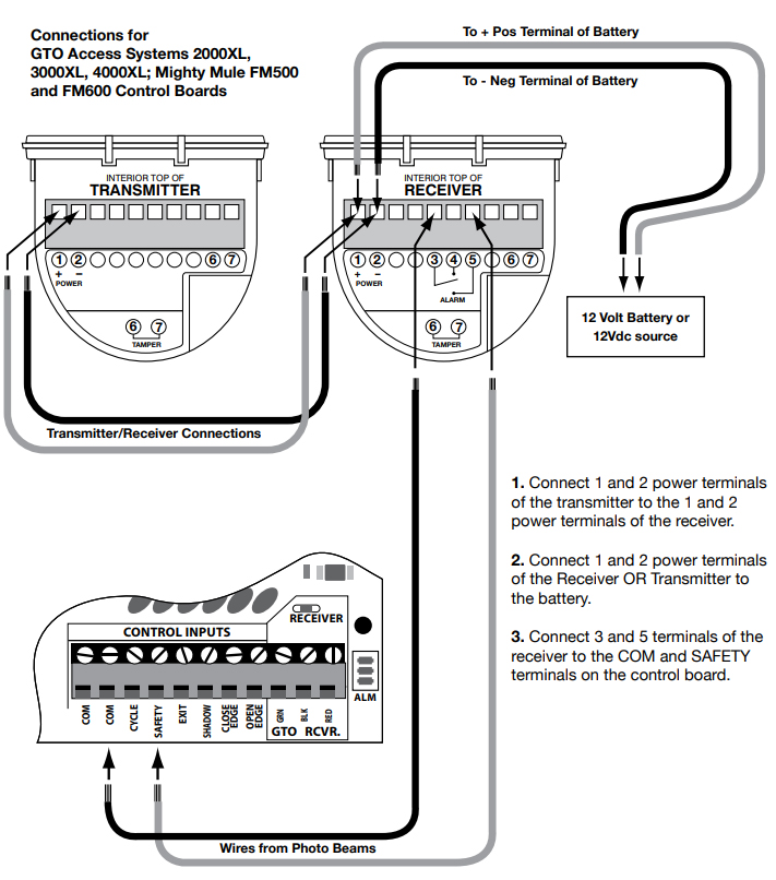
Connecting photo beams to gto/pro and mighty mule control boards terminal strip identification make sure the power switch to the opener is turned off. The installed onto standard two gang electrical box, or directly by drilling the holes and fixing with plugs. Mounting position beam detectors require a very stable mounting surface for proper Connecting photo beams to gto/pro and mighty mule control boards terminal strip identification make sure the power switch to the opener is turned off. Beam is a conventional device, below are suggested wiring configurations for single and multi heads on a zone.
 Source: medium.com
Connecting photo beams to gto/pro and mighty mule control boards terminal strip identification make sure the power switch to the opener is turned off. Projected beam smoke detector 3825 ohio avenue, st. D4120 duct smoke detector the innovairflex series are the only duct smoke detectors flexible enough to. Thefirebeam can easily be made addressable with the use of a manufacturers interface and in some cases can also be powered from the loop, ie with the apollo xp95 switch monitor with isolator. Parts diagram (not to scale):
 Source: wholefoodsonabudget.com
Rec eiv r connecting wires to the terminals (normally open wiring). The installed onto standard two gang electrical box, or directly by drilling the holes and fixing with plugs. Be sure to connect the power supply wires to terminal 1 and 2. Reflected optical beam smoke detectors utilises less wiring for reduced installation costs (power and wiring are only required at the transceiver end) and only requires the transceiver to be aligned. Projected beam smoke detector 3825 ohio avenue, st.
 Source: makingcircuits.com
D4120 duct smoke detector the innovairflex series are the only duct smoke detectors flexible enough to. Diagram illustrates correct placement of photo beams in relation to the gate. Rec eiv r connecting wires to the terminals (normally open wiring). Connecting photo beams to gto/pro and mighty mule control boards terminal strip identification make sure the power switch to the opener is turned off. It explains how it works, the features you get as standard, as well as information about our kits and accessories.
 Source: acornfiresecurity.com
Smoke detectors intercommunicate so that all detectors will sound if one is triggered. The main supply is 120v ac (in us) and 230v ac (in eu). Generic wiring diagram on the following page). Reflective optical beam smoke detector user guide 1 distance and position guidelines. Reflected optical beam smoke detectors utilises less wiring for reduced installation costs (power and wiring are only required at the transceiver end) and only requires the transceiver to be aligned.
 Source: manualsdir.com
Model d4120 and d4s duct smoke detectors utilize 4 wire photoelectric tech nology for the detection of smoke. Be sure to connect the power supply wires to terminal 1 and 2. Unique detection technology the osid system measures the level of smoke entering beams of light projected over an area of protection. Screw in through holes provided outside of the rubber seal. Connecting photo beams to gto/pro and mighty mule control boards terminal strip identification make sure the power switch to the opener is turned off.
 Source: optex-fa.com
Mounting position beam detectors require a very stable mounting surface for proper Specifications are subject to change without notice. The beamsmk allows system sensor reflected beam detectors to be mounted when surface wiring is used. Frightprops support dr18 cylinderical photoelectric wiring toy car sd timer adafruit using a break beam sensor with python photoelectric sensor wiring setup and. System sensor model beam/beams is a long range projected beam.
 Source: pinterest.jp
For us installations it is typically a short circuit. Connecting photo beams to gto/pro and mighty mule control boards terminal strip identification make sure the power switch to the opener is turned off. Diagram illustrates correct placement of photo beams in relation to the gate. If wired wrongly, the apparatus may break down. A smoke or heat detector can be installed to the existing or new home wiring.
This site is an open community for users to do submittion their favorite wallpapers on the internet, all images or pictures in this website are for personal wallpaper use only, it is stricly prohibited to use this wallpaper for commercial purposes, if you are the author and find this image is shared without your permission, please kindly raise a DMCA report to Us.
If you find this site good, please support us by sharing this posts to your own social media accounts like Facebook, Instagram and so on or you can also save this blog page with the title beam detector wiring diagram by using Ctrl + D for devices a laptop with a Windows operating system or Command + D for laptops with an Apple operating system. If you use a smartphone, you can also use the drawer menu of the browser you are using. Whether it’s a Windows, Mac, iOS or Android operating system, you will still be able to bookmark this website.

