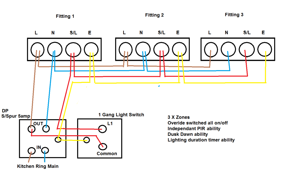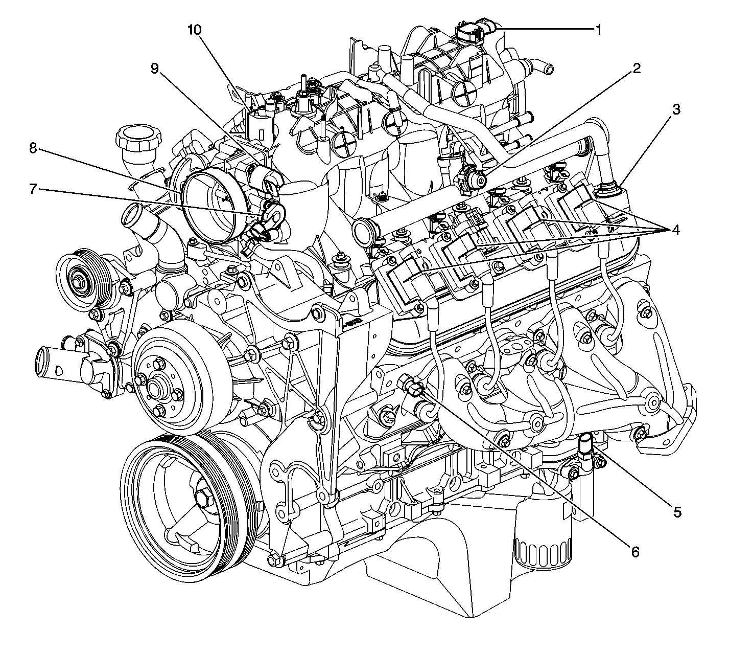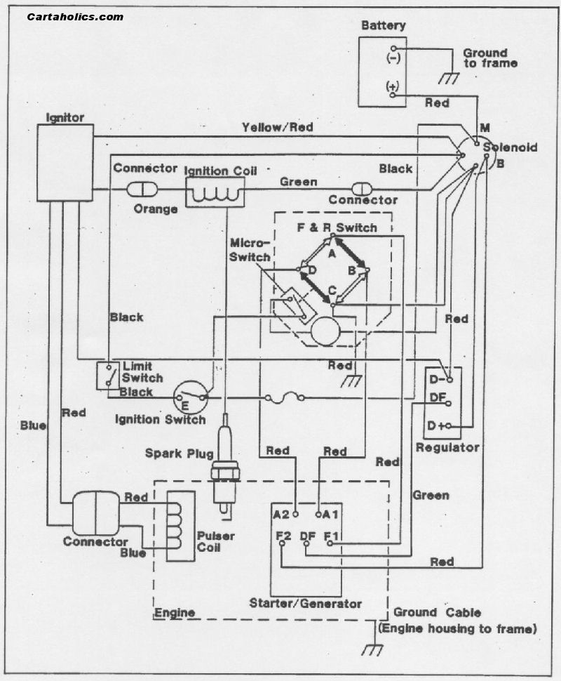
Your Basic indicator wiring diagram images are ready in this website. Basic indicator wiring diagram are a topic that is being searched for and liked by netizens now. You can Download the Basic indicator wiring diagram files here. Get all royalty-free images.
If you’re looking for basic indicator wiring diagram pictures information related to the basic indicator wiring diagram topic, you have come to the ideal blog. Our website always gives you suggestions for viewing the highest quality video and picture content, please kindly hunt and find more enlightening video content and graphics that fit your interests.
Basic Indicator Wiring Diagram. Basic diesel engine wiring diagram wiring diagram is a simplified suitable pictorial representation of an electrical circuit. 12v battery level indicator with led dot bargraph display suitable for automobile lead acid batteries. First, it shows ac main or the power grid. Relay can be the best option to control electrical devices automatically.
 Indicator warning light. Electrical / Instruments by From lotuselan.net
A wiring diagram is a simple visual representation of the physical connections and physical layout of an electrical system or circuit. There are different kinds of relays for different purposes. So todays wiring is pretty good. In the circuit diagram, there are 2 leds for showing 2 status. Simple water level indicator circuits schematic of alarm circuit diagram easy electronics projects with buzzer sensor or liquid detector full using 7 segment system automatic controller ic uln2003 working anti corrossive probe arduino numeric 2 for submersible 555 timer 1 12 stage how works the stop tank overflow wireless atmega32 avr hot It is not difficult to learn the basic symbols.
Wiring diagram for indicator relay.
5 pin is compromised of 3 main. • from the switch the cable feeds a light. The diagram is shown with 6a lighting fuse and 32a ring circuit mcb. This unit needs to be wired in conjunction with a suitable flasher unit and brake light switch. A wiring diagram is a simple visual representation of the physical connections and physical layout of an electrical system or circuit. Crimp and solder male and female bullet connectors.
 Source: pinterest.co.uk
It can be used for various switching. Basic car indicator wiring diagram. The factory wire color from the sensor is dg/w. Its easy factory switch most of you will have a hotrod that uses a steering column that has a turn signal switch built in. A wiring diagram is a simple visual representation of the physical connections and physical layout of an electrical system or circuit.
 Source: motorcyclezombies.com
On off on toggle switch for building custom 12v indicator flasher systems. But the rear warning lamp indicator doesnt light. • from the receptacle the cable feeds a switch. The composite diagram is shown here: Wiring diagrams show the connections to the controller.
 Source: uktriker.uk
Simple indicator wiring diagram wiring diagram and schematic. The diagram above is the 5 pin relay wiring diagram. Elementary diagram connections wire numbering. Collection of 3 pin led flasher relay wiring diagram. 1) power for the flasher is shifted from term #15 to #30, which is live all the time.
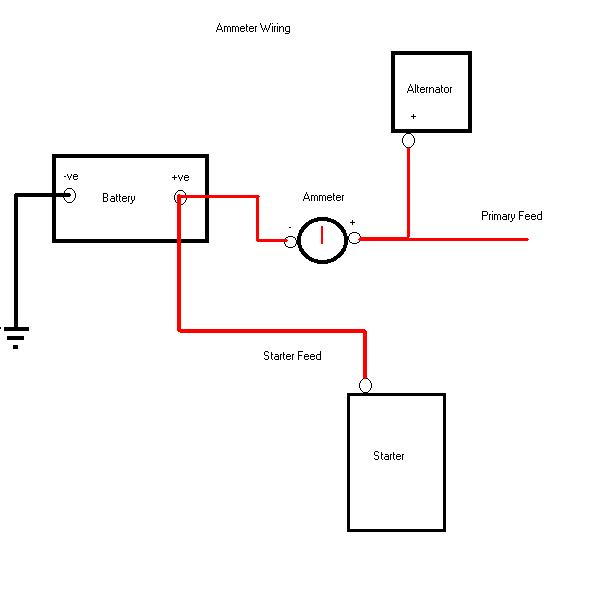 Source: chevyhhr.net
Relay can be the best option to control electrical devices automatically. Fully explained home electrical wiring diagrams with pictures including an actual set of house plans that i used to wire a new home. The composite diagram is shown here: Choose from the list below to navigate to various rooms of this home*. A wiring diagram is a simplified standard photographic representation of an electric circuit.
Source: aquastat-wiring-diagram55.blogspot.com
This is ac line led indicator circuit, that is compatible with the ac main power is 115 vac or 230 vac. Volvo back as my main squeeze, more boost and some interior goodies on the way. This is a universal 2pin led indicator relay for motorcycles and is provided with a basic wiring diagram to show how to hardwire it in. This applies to all old cub cadet ford jacobsen john deere wheel horse case and simplicity garden tractors. A wiring diagram is a simple visual representation of the physical connections and physical layout of an electrical system or circuit.
Source: rebablakuf.blogspot.com
There are different kinds of relays for different purposes. Amperage or ampacity, temperature, whether the wires are bundled closely together, and voltage drop. Collection of 3 pin led flasher relay wiring diagram. Dodge neon 2 0 1998 engine electrical circuit wiring diagram carfusebox. A wiring diagram is a simple visual representation of the physical connections and physical layout of an electrical system or circuit.
 Source: forum.retro-rides.org
There are different kinds of relays for different purposes. This is the circuit diagram of a simple corrosion free water level indicator for home and industries. The circuit is based on 5 transistor switches. When the switch is pulled out: 1) power for the flasher is shifted from term #15 to #30, which is live all the time.
 Source: circuits-diy.com
Volvo back as my main squeeze, more boost and some interior goodies on the way. Simple water level indicator circuits schematic of alarm circuit diagram easy electronics projects with buzzer sensor or liquid detector full using 7 segment system automatic controller ic uln2003 working anti corrossive probe arduino numeric 2 for submersible 555 timer 1 12 stage how works the stop tank overflow wireless atmega32 avr hot Fully explained home electrical wiring diagrams with pictures including an actual set of house plans that i used to wire a new home. Simple 12v battery status indicator level circuit easy 12 volt voltage lm3914 off 52 diagram uses full charge 59 3 led state with arduino monitor 9v low 555 for batteries 62 car charging scheme of lead acid circuits lm324 51 using 100ah charger diy cur indicators gel cell. On off on toggle switch for building custom 12v indicator flasher systems.
 Source: kit-car-build.com
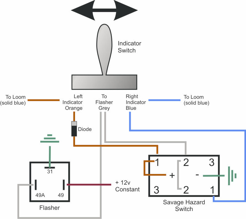
The wiring diagram is a bit fuzzy but from what i can make out there is a single indicator warning bulb that connects the left and ride sets of indicators. In this case, the green wire is the power wire which is feeding both the. First, it shows ac main or the power grid. Collection of 3 pin led flasher relay wiring diagram. Aye, fixed the troublesome non functioing indicators in my last mk5 simply by plugging the hazzard light switch back in.
 Source: wiringschemas.blogspot.com
They show the relative location of the components. I�ve no idea what you were typing into google. A car wiring diagram is a map. In the circuit diagram, there are 2 leds for showing 2 status. The switch connected both rear lights to the flasher.
![[DIAGRAM] Gm Turn Signal Switch Wiring Diagram FULL [DIAGRAM] Gm Turn Signal Switch Wiring Diagram FULL](https://c2.staticflickr.com/8/7217/7258224382_df03daf9c5_b.jpg) Source: cleverdiagramacao.hr-planet.it
Source: cleverdiagramacao.hr-planet.it
Simple water level indicator circuits schematic of alarm circuit diagram easy electronics projects with buzzer sensor or liquid detector full using 7 segment system automatic controller ic uln2003 working anti corrossive probe arduino numeric 2 for submersible 555 timer 1 12 stage how works the stop tank overflow wireless atmega32 avr hot 12v battery level indicator with led dot bargraph display suitable for automobile lead acid batteries. But the rear warning lamp indicator doesnt light. Refer to wiring diagram as a reference for installation; Basic car indicator wiring diagram.
 Source: dentistmitcham.com
In this case, the green wire is the power wire which is feeding both the. Draw a diagram to map out your wires and connections. The diagram above is the 5 pin relay wiring diagram. It shows how the electrical wires are interconnected and can also show where fixtures and components may be connected to the system. A car wiring diagram is a map.
 Source: tonetastic.info
Wiring a single pole switch source: But the rear warning lamp indicator doesnt light. Fully explained home electrical wiring diagrams with pictures including an actual set of house plans that i used to wire a new home. • from the switch the cable feeds a light. The composite diagram is shown here:
Source: wiringdiagramexamples.blogspot.com
This is the circuit diagram of a simple corrosion free water level indicator for home and industries. This is the circuit diagram of a simple corrosion free water level indicator for home and industries. The factory vss + (feed) wire can be found behind the lh (driver side) kick panel. A wiring diagram is a simple visual representation of the physical connections and physical layout of an electrical system or circuit. When the switch is pulled out:
 Source: stairwaytogyaru.blogspot.com
There are two wires occupying this location. Wiring diagram for indicator relay. 2# ac line indicator circuit. So todays wiring is pretty good. Here are the basic steps for how to wire a motorcycle:
 Source: lotuselan.net
Next measure the required length of your wire. A car wiring diagram is a map. It shows how the electrical wires are interconnected and can also show where fixtures and components may be connected to the system. When the switch is pulled out: Classic bike wiring diagrams regarding simple indicator wiring diagram, image size 506 x 365 px, and to view image details please click the image.
 Source: justanswer.com
Always shut off the power and check the wires with a voltage tester. There are two wires occupying this location. The wiring diagram is a bit fuzzy but from what i can make out there is a single indicator warning bulb that connects the left and ride sets of indicators. A car wiring diagram is a map. Classic bike wiring diagrams regarding simple indicator wiring diagram, image size 506 x 365 px, and to view image details please click the image.
 Source: untpikapps.com
The factory wire color from the sensor is dg/w. Always shut off the power and check the wires with a voltage tester. It shows the components of the circuit as simplified shapes and the facility and signal contacts surrounded by the devices. • from the switch the cable feeds a light. Simple 12v battery status indicator level circuit easy 12 volt voltage lm3914 off 52 diagram uses full charge 59 3 led state with arduino monitor 9v low 555 for batteries 62 car charging scheme of lead acid circuits lm324 51 using 100ah charger diy cur indicators gel cell.
This site is an open community for users to do sharing their favorite wallpapers on the internet, all images or pictures in this website are for personal wallpaper use only, it is stricly prohibited to use this wallpaper for commercial purposes, if you are the author and find this image is shared without your permission, please kindly raise a DMCA report to Us.
If you find this site helpful, please support us by sharing this posts to your favorite social media accounts like Facebook, Instagram and so on or you can also save this blog page with the title basic indicator wiring diagram by using Ctrl + D for devices a laptop with a Windows operating system or Command + D for laptops with an Apple operating system. If you use a smartphone, you can also use the drawer menu of the browser you are using. Whether it’s a Windows, Mac, iOS or Android operating system, you will still be able to bookmark this website.


