Your Ballast resistor wiring diagram points images are available in this site. Ballast resistor wiring diagram points are a topic that is being searched for and liked by netizens today. You can Download the Ballast resistor wiring diagram points files here. Download all free photos.
If you’re looking for ballast resistor wiring diagram points pictures information linked to the ballast resistor wiring diagram points topic, you have visit the right blog. Our site always provides you with suggestions for seeking the highest quality video and image content, please kindly surf and find more enlightening video content and graphics that match your interests.
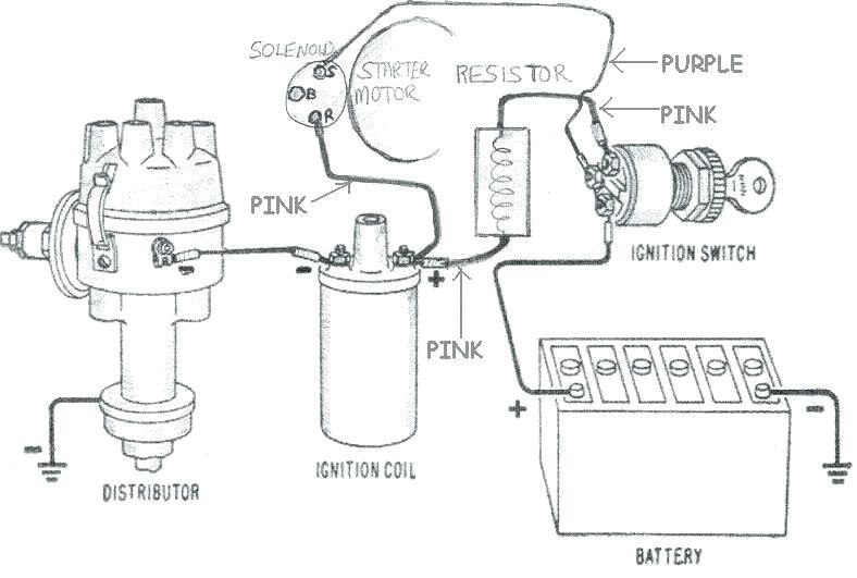
Ballast Resistor Wiring Diagram Points. (if battery has 12+) if 12 at coil, mount resistor on firewall (they get hot), run wire from ign to input side, check output side voltage. The ballast bypass wire from starter connects to coil+ and should supply full battery voltage to coil only during cranking. This simple system is easy for even the novice mechanic to wire. A ballast resistor is used in a device to compensate for changes and secure the other components of a network.
![[DIAGRAM] Ignition Coil Ballast Resistor Wiring Diagram [DIAGRAM] Ignition Coil Ballast Resistor Wiring Diagram](https://annawiringdiagram.com/wp-content/uploads/2019/02/how-to-wire-a-ballast-resistor-diagram-chevy-350-ignition-coil-ignition-coil-wiring-diagram-1024x768.jpg) [DIAGRAM] Ignition Coil Ballast Resistor Wiring Diagram From wiringestimatesk.netna.it
[DIAGRAM] Ignition Coil Ballast Resistor Wiring Diagram From wiringestimatesk.netna.it
A ballast resistor lowers line voltage from the battery level to a level that the points can live with. How do you wire in the ballast resistor. Ballast resistor wiring diagram points burning: Disconnect the negative terminal of the battery, if there is one installed on the car. When the current flowing through the resistor increase, the temperature also increases. The ballast bypass wire from starter connects to coil+ and should supply full battery voltage to coil only during cranking.
Bypass any resistance unit to provide full 12v key on power to the coil and module.
Ballast resistor wiring diagram c2 ballast resistor with electronic ignition. When hooking up the ignition to the coil there is 12v. There are two different types of ballast resistors, a ceramic type that is mounted to firewall or fenderwell, and another that is literally a set length of. Get ballast resistor wiring diagram points pics. Diagram attached for wiring of points dizzy and coil with ballast resistor. In a points type ignition the ballast resistor would help to keep the spark down and the coil from being burned up too quickly.
![[DIAGRAM] Ignition Coil Ballast Resistor Wiring Diagram [DIAGRAM] Ignition Coil Ballast Resistor Wiring Diagram](https://annawiringdiagram.com/wp-content/uploads/2019/02/how-to-wire-a-ballast-resistor-diagram-chevy-350-ignition-coil-ignition-coil-wiring-diagram-1024x768.jpg) Source: wiringestimatesk.netna.it
Source: wiringestimatesk.netna.it
A ballast resistor may also be included in this system. In simple terms the ballast resistor in a mopar limits the amperage or current flow through the coil while the engine is running thereby extending the life of the coil and breaker points of. October 25, 2019 1 margaret byrd. I�m trying to wire the bypass wire on the schematics. Ballast resistor wiring diagram points.

Ballast resistor wiring diagram c2 ballast resistor with electronic ignition. A resistor wire or ballast resistor may or may not be included in the original equipment. In a points type ignition the ballast resistor would help to keep the spark down and the coil from being burned up too quickly. What is causing my points on my 460 ford. A ballast resistor lowers line voltage from the battery level to a level that the points can live with.
 Source: mgbreakers.com
Get ballast resistor wiring diagram points pics. My wiring diagram has a line with a squiggle. If 9 or so, connect wire to coil +. A ballast resistor is used in a device to compensate for changes and secure the other components of a network. Wiring diagram for chrysler electronic ignition wiring the coil ballast wiring whether 4 or 2 wire is unchanged from points.

My wiring diagram has a line with a squiggle. If you have 9 or so, it may be resistance wire. If 9 or so, connect wire to coil +. A ballast resistor lowers line voltage from the battery level to a level that the points can live with. Com3623928 amazon kindle edition whiteboard description of the operation of a 3 wire coil on plug ignition system.
 Source: wiringdiagram.2bitboer.com
A ballast resistor may also be included in this system. The ballast bypass wire from starter connects to coil+ and should supply full battery voltage to coil only during cranking. Connect one side of the ballast resistor to the positive side of the coil. In a points type ignition the ballast resistor would help to keep the. If 9 or so, connect wire to coil +.
![[DIAGRAM] Ignition Coil Ballast Resistor Wiring Diagram [DIAGRAM] Ignition Coil Ballast Resistor Wiring Diagram](https://desbennettconsultants.netlify.app/img/placeholder.svg)
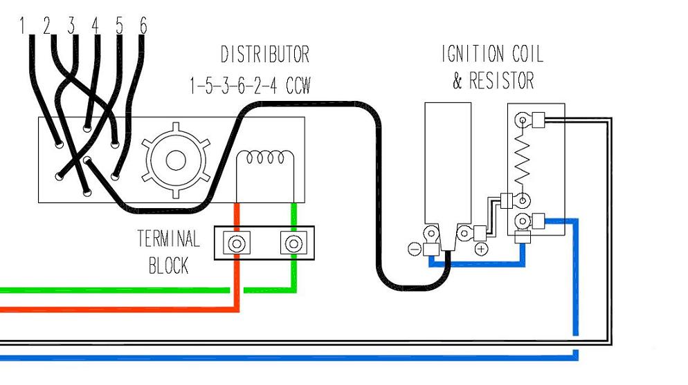
Ballast resistor wiring diagram c2 ballast resistor with electronic ignition. Each component ought to be set and linked to different parts in specific way. They are additionally beneficial for making fixings. According to the wiring diagram i have it goes to the ignition switch. Diagram attached for wiring of points dizzy and coil with ballast resistor.
 Source: classiczcars.com
There are two different types of ballast resistors, a ceramic type that is mounted to firewall or fenderwell, and another that is literally a set length of. In a points type ignition the ballast resistor would help to keep the. A ballast resistor lowers line voltage from the battery level to a level that the points can live with. Each component ought to be set and linked to different parts in specific way. Discussion in 1960 1966 started by ol betsy dec 20 2006.

If you set up a battery on a bench and hook up all the wires as shown you can check the spark by toggling the point lead (#5) to ground. Ignition troubleshooting ballast resistor bmw 2002 compatible coils diagram coil wiring accuspark diagrams 1967 points ford 34 how to replace a igniter and with texas t dist keeps burning condensers issue 71 302 only runs in. In the towns around fort bragg, north carolina, retired special forces soldiers apply to their companies what they. Ignition systems a short course carparts com ignition system car. Wiring diagram comes with a number of easy to adhere to wiring diagram instructions.
 Source: facybulka.me
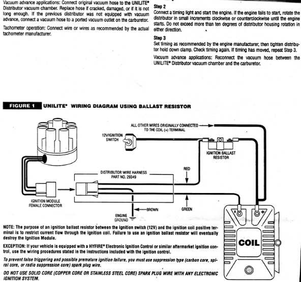
Ignition coil ballast resistor wiring diagram ignition coil coil ballast us standards are black is hot white is neutral green is ground or just a solid copper wire. In a points type ignition the ballast resistor would help to keep the spark down and the coil from being burned up too quickly. Discussion in 1960 1966 started by ol betsy dec 20 2006. The collection that comprising chosen picture and the best amongst others. Jan 01 2008 the purpose of the ign1 and ign2 is to supply a full 12 volts to a points type ignition for starting and to use a ballast resistor for running.
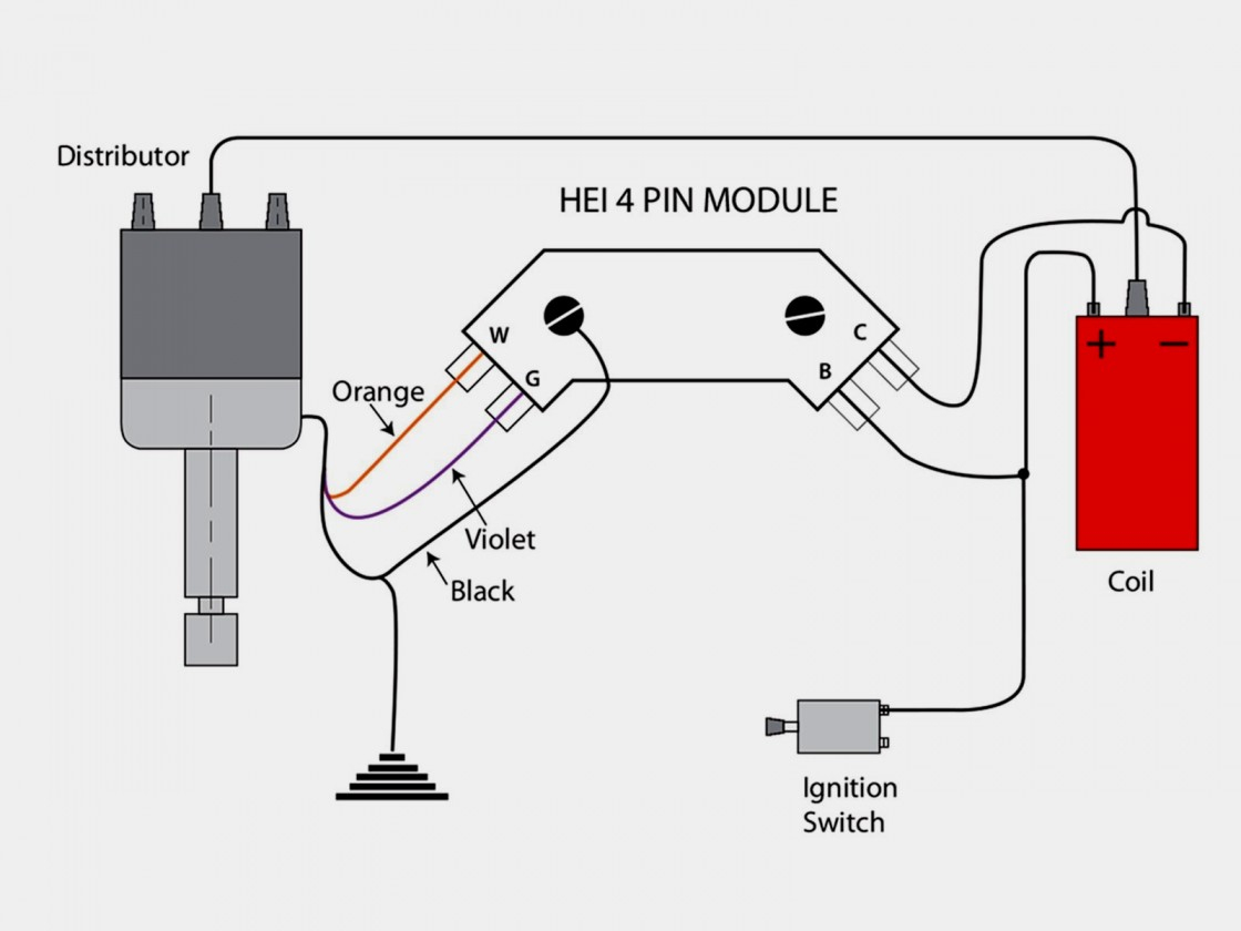 Source: 2020cadillac.com
Ignition systems a short course carparts com ignition system car. A ballast resistor may also be included in this system. Disconnect the negative terminal of the battery, if there is one installed on the car. The typical automotive ignition system prior to 1974 consisted of a coil and ballast resistor, with breaker points to interrupt the current flow when a spark was needed. Diagram attached for wiring of points dizzy and coil with ballast resistor.
 Source: elortodehiguain.blogspot.com
It is supposed to aid each of the typical user in creating a correct method. 150001 or oem ballast figure 2 accel points eliminator wiring diagram using ballast. What is causing my points on my 460 ford. Ignition troubleshooting ballast resistor bmw 2002 compatible coils diagram coil wiring accuspark diagrams 1967 points ford 34 how to replace a igniter and with texas t dist keeps burning condensers issue 71 302 only runs in. I have a white wire from the ignition switch which when attached to the coils gives me a spark but i can�t get a spark through the resistor.

This simple system is easy for even the novice mechanic to wire. Have replaced these just for no dash light issue before. Connect one side of the ballast resistor to the positive side of the coil. The two systems work in completely different ways. The typical automotive ignition system prior to 1974 consisted of a coil and ballast resistor with breaker points to interrupt the current flow when a spark was needed.

Points, transistorized ignition, hei and probably a bunch of other names used by someone as marketing wank connects battery voltage to the coil (sometimes through a ballast resistor) to slowly let the magnetic field build inside the coil, and store energy in it. If 9 or so, connect wire to coil +. If you set up a battery on a bench and hook up all the wires as shown you can check the spark by toggling the point lead (#5) to ground. Ballast resistor wiring diagram points have an image from the other. If you have 9 or so, it may be resistance wire.

The typical automotive ignition system prior to 1974 consisted of a coil and ballast resistor, with breaker points to interrupt the current flow when a spark was needed. (if battery has 12+) if 12 at coil, mount resistor on firewall (they get hot), run wire from ign to input side, check output side voltage. A resistor that has the property of increasing in resistance as current flowing through it increases and decreasing in resistance as current decreases. In a points type ignition the ballast resistor would help to keep the. Ballast resistor wiring diagram c2 ballast resistor with electronic ignition.
 Source: facybulka.me
Ballast resistor wiring diagram points. Disconnect the negative terminal of the battery, if there is one installed on the car. Ballast resistor wiring diagram points have an image from the other. My wiring diagram has a line with a squiggle. Wiring diagram comes with a number of easy to adhere to wiring diagram instructions.
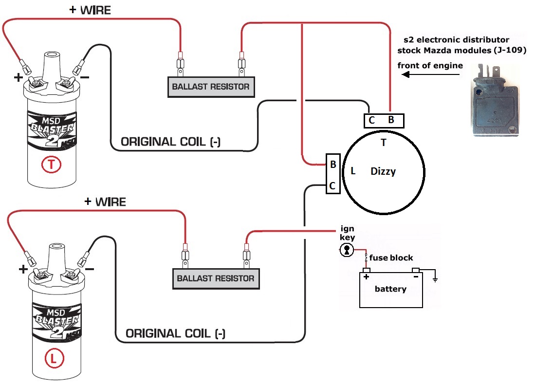 Source: nopistons.com
Ballast resistor wiring diagram points have an image from the other. It is supposed to aid each of the typical user in creating a correct method. 2 stroke ignition coil wiring diagram email protected gsm wiring diagram 4. 150001 or oem ballast figure 2 accel points eliminator wiring diagram using ballast. They are additionally beneficial for making fixings.
 Source: amee055.blogspot.com
There are two different types of ballast resistors, a ceramic type that is mounted to firewall or fenderwell, and another that is literally a set length of. These directions will be easy to understand and implement. What is causing my points on my 460 ford. A resistor wire or ballast resistor may or may not be included in the original equipment. Ballast resistor wiring diagram points.
 Source: alannahbig.blogspot.com
I have a white wire from the ignition switch which when attached to the coils gives me a spark but i can�t get a spark through the resistor. Otherwise, the structure will not function as it should be. (if battery has 12+) if 12 at coil, mount resistor on firewall (they get hot), run wire from ign to input side, check output side voltage. Points, transistorized ignition, hei and probably a bunch of other names used by someone as marketing wank connects battery voltage to the coil (sometimes through a ballast resistor) to slowly let the magnetic field build inside the coil, and store energy in it. When the current flowing through the resistor increase, the temperature also increases.
This site is an open community for users to submit their favorite wallpapers on the internet, all images or pictures in this website are for personal wallpaper use only, it is stricly prohibited to use this wallpaper for commercial purposes, if you are the author and find this image is shared without your permission, please kindly raise a DMCA report to Us.
If you find this site value, please support us by sharing this posts to your own social media accounts like Facebook, Instagram and so on or you can also bookmark this blog page with the title ballast resistor wiring diagram points by using Ctrl + D for devices a laptop with a Windows operating system or Command + D for laptops with an Apple operating system. If you use a smartphone, you can also use the drawer menu of the browser you are using. Whether it’s a Windows, Mac, iOS or Android operating system, you will still be able to bookmark this website.


