Your Balanced to unbalanced wiring diagram images are ready. Balanced to unbalanced wiring diagram are a topic that is being searched for and liked by netizens now. You can Find and Download the Balanced to unbalanced wiring diagram files here. Download all free photos and vectors.
If you’re looking for balanced to unbalanced wiring diagram images information linked to the balanced to unbalanced wiring diagram topic, you have visit the right site. Our website always gives you hints for seeing the maximum quality video and image content, please kindly hunt and find more enlightening video content and images that match your interests.
Balanced To Unbalanced Wiring Diagram. When connecting from 75 ohm unbalanced to 110 ohm balanced, all you need is a transformer with a 1:1.21 turns ratio, with appropriate connectors. 2:if the signal source is equipped with a cross coupled output stage:(see remarks below). The shield serves to guard the sensitive audio lines from interference. Two signals wires plus a separate ground wire.
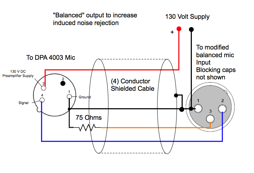 Xlr To 1/4 Balanced Wiring Diagram From schematron.org
This book have some digitalformats such us : Nilfisk alto mac 2 3 4 users manual nf01893 mac t c. If you are wiring to a balanced stereo jack plug positive is the tip negative is the ring and ground is the sleeve. With non tranny gear pin 1 to the shell and pin 2 goes to the center tip of the rca. Wiring audio inputs and outputs biamp systems. Signals flow from one piece of equipment to another via these two wires.
Write the characteristics shared by unbalanced and balanced forces in the area of overlap.
If you are wiring to a balanced stereo jack plug positive is the tip negative is the ring and ground is the sleeve. As in the unbalanced cable, the ground wire still surrounds the signal wires and is used as a shield against interference. Unbalanced input trs connector rca connect or left right left right balanced input or output balanced mono audio unbalanced st ereo audio tip sleeve sleeve ring unbalanced output left tip sleev e(s) no ground here no ground here tip right caution for unbalanced audio , connect the sleeves to the ground contact. Electronic wiring majorcom the cable connection balanced and unbalanced soldering schematics how to white noise studio audio cables my second brain xlr connector rca diagram. Balanced to unbalanced wiring book file pdf. Balance 1 4 jack wiring output jack znlhj adtddns asia.
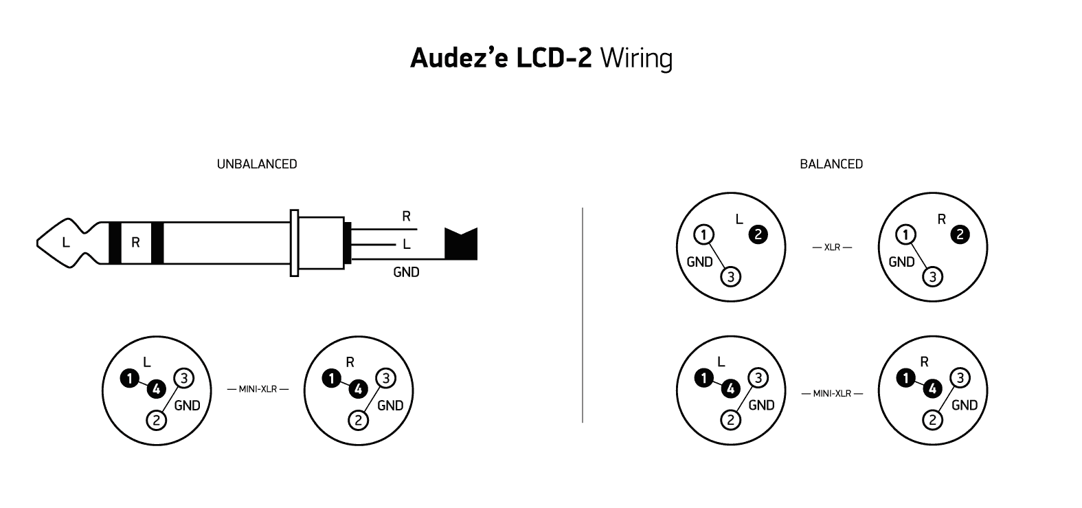 Source: schematron.org
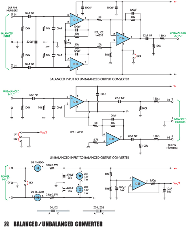
Balanced audio wiring diagram wiring schematic diagram. If you are wiring to a balanced stereo jack plug positive is the tip negative is the ring and ground is the sleeve. Balanced audio cable wiring diagram wiring diagram line wiring diagram. This balanced/unbalanced converter is really two projects in one. Unfortunately i need a wiring diagram like above, or i�m lost.
 Source: boxcast.com
On xlr to 1/4 balanced wiring diagram. 23.11.2020 · the more unbalanced the load and the longer the wiring, the greater the voltage offset of the device housing to the ground. This produces an unbalanced output that can be used to feed an unbalanced input via either a ts or trs plug. Balance 1 4 jack wiring output jack znlhj adtddns asia. I�d like to build a bosoz and use it as a bal to unbal converter to run the soz, but i�m not sure if i can wrap my head around building a preamp like that.
 Source: schematron.org
St da3 line level distribution amplifier The audio is impressed on the one active or hot wire. Wiring a directv genie (hr34/hr44), 3 clients (c31s) and deca. For unbalanced connections the biamp default output level of 24dbu may be too high. This produces an unbalanced output that can be used to feed an unbalanced input via either a ts or trs plug.
 Source: boxcast.com
Unbalanced is utilizing one active wire and one ground/shield wire return for a single audio feed. St da3 line level distribution amplifier Signals flow from one piece of equipment to another via these two wires. Mic wire wiring wiring diagram 500. This is commonly referred to as the studiohub wiring standard.
![[DIAGRAM in Pictures Database] U57fa U677f U30fblsi U4e8b [DIAGRAM in Pictures Database] U57fa U677f U30fblsi U4e8b](https://i.ytimg.com/vi/q2mmoU37SDo/maxresdefault.jpg) Source: lakesideministry.com
Source: lakesideministry.com
A balanced cable, by contrast, has three conductors in the connector and three wires in the cable: Practically anything that moves is a result of the exertion of unbalanced forces on it. Two signals wires plus a separate ground wire. But what makes a balanced cable special is the way the gear utilizes that. The audio is impressed on the one active or hot wire.
 Source: cuartifusavisual.blogspot.com
Xlr to 1 4 trs connector wired for balanced mono the usual way to connect a 3 pin xlr to a 1 4 trs aka stereo jack plug is to use the following pin. For this wiring scheme, two input channels are required; It can convert an unbalanced input to balanced outputs and vice versa. Always use twisted pair cable. Wiring a directv genie (hr34/hr44), 3 clients (c31s) and deca.
 Source: harmonycentral.com
It can also be used to feed a balanced cable and input via a trs plug. With non tranny gear pin 1 to the shell and pin 2 goes to the center tip of the rca. Mic wire wiring wiring diagram 500. The cable w wire across pins 1 3 goes from rca out of pre into male xlr at amp. When connecting balanced outputs to unbalanced inputs the big question that must come up with what to do with that third wire?

The audio is impressed on the one active or hot wire. Pin 2 on the xlr is hot and carries the positive going signal whilst pin 3 is cold and provides the return. Nilfisk alto mac 2 3 4 users manual nf01893 mac t c. It can convert an unbalanced input to balanced outputs and vice versa. The cable w wire across pins 1 3 goes from rca out of pre into male xlr at amp.
 Source: kc.flexradio.com
Kindle, epub, ebook, paperbook, and another formats. St da3 line level distribution amplifier It can also be used to feed a balanced cable and input via a trs plug. Female balanced xlr →to→ male unbalanced 1/4 (6.3mm) or 3.5mm jack. Wiring diagram for a 13pin euro trailer plug.
 Source: learningelectronics.net
For this wiring scheme, two input channels are required; St da3 line level distribution amplifier Mic wire wiring wiring diagram 500. 23.11.2020 · the more unbalanced the load and the longer the wiring, the greater the voltage offset of the device housing to the ground. This book have some digitalformats such us :
 Source: avcssguitarworld.com
Balanced line output / unbalanced line output. But what makes a balanced cable special is the way the gear utilizes that. Unbalanced input trs connector rca connect or left right left right balanced input or output balanced mono audio unbalanced st ereo audio tip sleeve sleeve ring unbalanced output left tip sleev e(s) no ground here no ground here tip right caution for unbalanced audio , connect the sleeves to the ground contact. On xlr to 1/4 balanced wiring diagram. When connecting from 75 ohm unbalanced to 110 ohm balanced, all you need is a transformer with a 1:1.21 turns ratio, with appropriate connectors.
 Source: tops-stars.com
Van den hul audio cable connector wiring diagrams female balanced xlr to male unbalanced rca fig. Signals flow from one piece of equipment to another via these two wires. Lowering the output level in the output. What�s shown in the schematic is the middle section of one half of our final cable. Mic wire wiring wiring diagram 500.
 Source: pinterest.com
Wiring audio inputs and outputs biamp systems. On the left is our balanced signal coming from our xlr cables, and on the right is our unbalanced cable. 1:if the signal source is equipped with a pseudo balanced output stage:(see remarks below). St da3 line level distribution amplifier Xlr 2 (hot) should go to jack tip, xlr 3 (cold) should go to jack ring, xlr 1 (ground) should go to jack sleeve the tn, rn and gn.
 Source: whitenoisestudio.com
The arrangement is shown in the block diagram on page 2 of the technical specification and enlarged in the owner�s manual(pdf) e.g. Apparently, this will convert whilst also maintaining the balancing of the xlr cable (which i don�t believe the other answers would) and so help to reduce noise. This balanced/unbalanced converter is really two projects in one. Wiring audio inputs and outputs biamp systems. File balanced to unbalanced wiring book free download pdf at our ebook library.

The arrangement is shown in the block diagram on page 2 of the technical specification and enlarged in the owner�s manual(pdf) e.g. If you are wiring to a balanced stereo jack plug positive is the tip negative is the ring and ground is the sleeve. A balanced cable, by contrast, has three conductors in the connector and three wires in the cable: When connecting from 75 ohm unbalanced to 110 ohm balanced, all you need is a transformer with a 1:1.21 turns ratio, with appropriate connectors. St da3 line level distribution amplifier
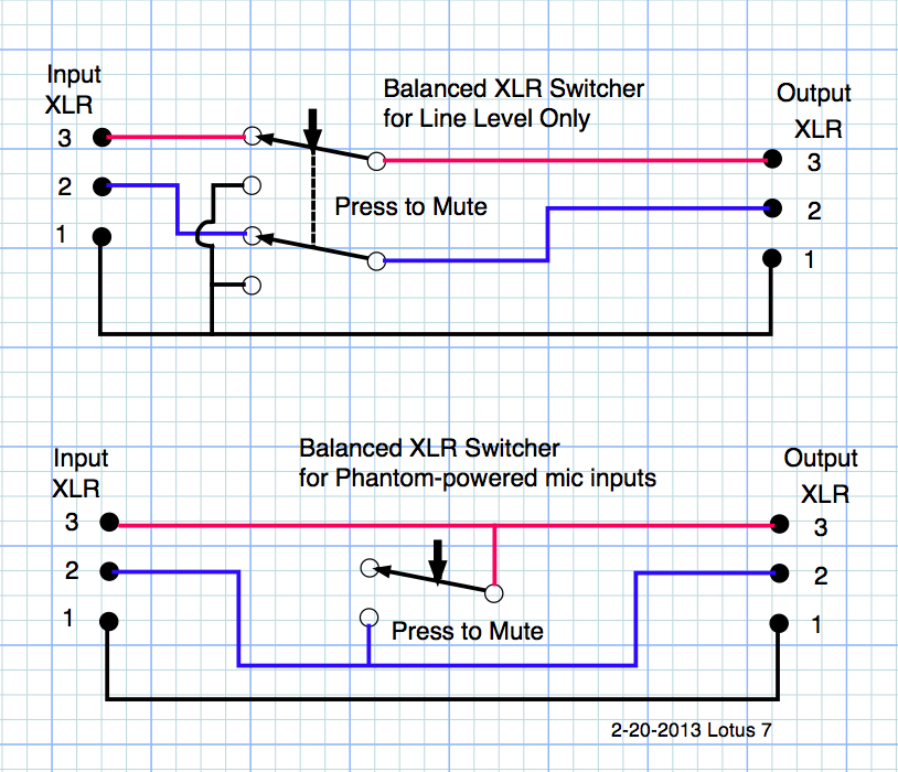 Source: schematron.org
Balanced line output / unbalanced line output. Lowering the output level in the output. The audio is impressed on the one active or hot wire. File balanced to unbalanced wiring book free download pdf at our ebook library. Pin 2 on the xlr is hot and carries the positive going signal whilst pin 3 is cold and provides the return.
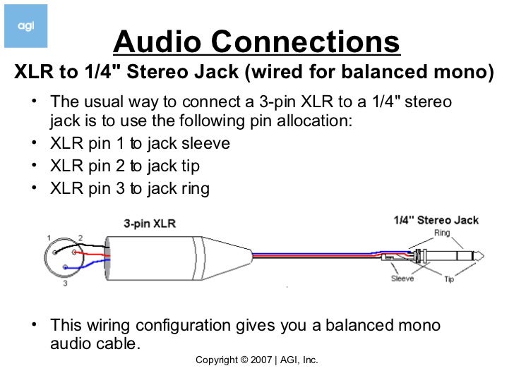 Source: schematron.org
Balanced and unbalanced forces venn diagram angelo on october 31, 2021 weather interactive notebook pages print and digital versions weather interactive notebook interactive notebooks interactive science notebook Mic wire wiring wiring diagram 500. Write the characteristics shared by unbalanced and balanced forces in the area of overlap. Mic wire wiring wiring diagram 500. Mic wire wiring wiring diagram 500.
This site is an open community for users to do sharing their favorite wallpapers on the internet, all images or pictures in this website are for personal wallpaper use only, it is stricly prohibited to use this wallpaper for commercial purposes, if you are the author and find this image is shared without your permission, please kindly raise a DMCA report to Us.
If you find this site convienient, please support us by sharing this posts to your preference social media accounts like Facebook, Instagram and so on or you can also save this blog page with the title balanced to unbalanced wiring diagram by using Ctrl + D for devices a laptop with a Windows operating system or Command + D for laptops with an Apple operating system. If you use a smartphone, you can also use the drawer menu of the browser you are using. Whether it’s a Windows, Mac, iOS or Android operating system, you will still be able to bookmark this website.
