Your Aware gps wiring diagram images are available. Aware gps wiring diagram are a topic that is being searched for and liked by netizens now. You can Get the Aware gps wiring diagram files here. Find and Download all royalty-free photos and vectors.
If you’re searching for aware gps wiring diagram pictures information related to the aware gps wiring diagram keyword, you have pay a visit to the right site. Our site frequently gives you suggestions for downloading the maximum quality video and image content, please kindly hunt and find more enlightening video content and graphics that match your interests.
Aware Gps Wiring Diagram. Only need to attach three of these wires to your vehicle (the additional wires are for future features or functions). If the transfer is interrupted, turn off the gps and then turn it back on. 4) note what the speedometer is indicating at a known 60mph. Your asset must be outside and not in a covered area so that it will receive gps signal.
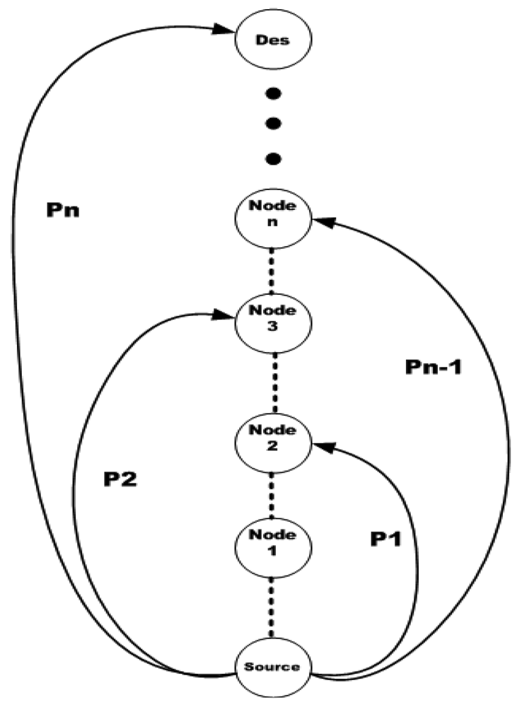
 Sensors Free FullText Joint Energy Supply and Routing From mdpi.com
Then add a g5 electronic flight instrument for backup, an optional gmc 507 autopilot controller for dedicated autopilot operation and a gtr 200 as a second comm radio. Be aware that the wiring diagram supplied with this stack has gnd and bat the wrong way round. Be aware of damaging any wiring, pipeline, and fuel tank of the.instructions and connection diagram, as improper installation may cause a fire. Problem doesn’t show up during usb config/build setup. 4) note what the speedometer is indicating at a known 60mph. Use the wiring diagram and information below to make the necessary wiring connections.
Grt sport sx, autopilot, gtx327, gps 175.
User manual, english, garmin gpsmap 76csx gps with 4gb memory card user manual. But when a > 3s lipo is connected, it fried my fc, my gps and my rx. The system will automatically use the source with the best reception. Be careful however, most gps modules are 3.3v. Both pairs must be connected to a 12/24 volt power supply (via fuse panel) so that the electrical load can be distributed evenly. The three wires you need are:
 Source: youtube.com
Turn off or pull out the ignition key before installation, as battery current leakage or short circuit may be caused when the engine is running. Support@awaregps.com the connector is located under the dash and is required to be within two feet of the steering wheel. 1 trick that we 2 to printing a. Follow these steps to install the device: Only need to attach three of these wires to your vehicle (the additional wires are for future features or functions).
 Source: ebay.com
Both pairs must be connected to a 12/24 volt power supply (via fuse panel) so that the electrical load can be distributed evenly. The three wires you need are: Locate the vehicle’s ignition wire (reference the vehicle’s wiring diagram in order to locate). I have been reading the other messages in this forum gps units. Next, using standard jumper wires, connect the modules together as per the wiring diagram.
 Source: mdpi.com
Combine 2 10.6 g3x touch panels as pfds, a single 7 display as an mfd and a gtn™ 650xi touchscreen navigator for gps/nav/comm functions. Use water, isopropyl alcohol, or. Cut and strip the red wire on the awaregps device connect the two red wires and crimp this connection provides power to the device connect the awaregps black wire to your vehicle’s chassis this connection serves as a ground for the device locate the vehicle’s ignition wire (reference the vehicle’s wiring diagram in order to locate). A wiring diagram is a simple visual representation of the physical connections and physical layout of an electrical system or circuit. If you have a wiring diagram that i can start from or have any tips, send pm me.
 Source: mdpi.com
Find the constant red power wire in your vehicle. Jan 19, 2022, 10:34 am #3; If you cannot locate the obd connector, Setup button on the home screen, then system settings, internal gps = off. Note that i didn�t include the power wiring in order to make the signal wiring more obvious.
 Source: mdpi.com
Only need to attach three of these wires to your vehicle (the additional wires are for future features or functions). Locate the vehicle’s ignition wire (reference the vehicle’s wiring diagram in order to locate). Grt sport sx, autopilot, gtx327, gps 175. The three wires you need are: Connect the black ground wire of the sn16f to a good chassis ground.
 Source: mdpi.com
Both pairs must be connected to a 12/24 volt power supply (via fuse panel) so that the electrical load can be distributed evenly. Note that i didn�t include the power wiring in order to make the signal wiring more obvious. Both pairs must be connected to a 12/24 volt power supply (via fuse panel) so that the electrical load can be distributed evenly. There is a built in gps on the e125 mfd. The system will automatically use the source with the best reception.
 Source: mdpi.com
Next, using standard jumper wires, connect the modules together as per the wiring diagram. J garmin aera 795/796 pilot’s guide warnings, cautions & notes caution: The osh team thus developed the geocam based on raspberry pi (rpi) using the rpi hd video camera, an adafruit gps, and an adafruit. The red wire (power), the longer of the two black wires (ground) and the white wire (ignition sense). Connect the red power wire of the sn16f to the red 5v wire of the gauge wire harness.
 Source: mdpi.com
Cut and strip the red wire on the awaregps device. Grt sport sx, autopilot, gtx327, gps 175. User manual, english, garmin gpsmap 76csx gps with 4gb memory card user manual. 3s wiring diagram 1 ph, 2 wire (1 pt, 1 ct) glems would like to thank and acknowledge the use of the following meter connection diagrams from dr. Connect the black ground wire of the sn16f to a good chassis ground.
 Source: mdpi.com
This connection serves as a ground for the device. Refer to the installation guide wiring diagram for information about connecting to an nmea 2000 network. 32 results for garmin gps 76csx save garmin. Calibrated speedometer or by using a gps. Its the gnd and bat nearest the boot button that are reversed.
 Source: mdpi.com
Your asset must be outside and not in a covered area so that it will receive gps signal. Your asset must be outside and not in a covered area so that it will receive gps signal. The three wires you need are: 1 trick that we 2 to printing a. I was hoping to gain some accelerated learning from anyone who may have a similar configuration:
 Source: mdpi.com
The three wires you need are: Then add a g5 electronic flight instrument for backup, an optional gmc 507 autopilot controller for dedicated autopilot operation and a gtr 200 as a second comm radio. Grt sport sx, autopilot, gtx327, gps 175. I have been reading the other messages in this forum gps units. Would like a wiring diagram of the system, handwritten would work, to see how everything is connected.
 Source: mdpi.com
Cut and strip the red wire on the awaregps device. Jan 19, 2022, 10:34 am #3; Turn off or pull out the ignition key before installation, as battery current leakage or short circuit may be caused when the engine is running. Use the wiring diagram and information below to make the necessary wiring connections. Grt sport sx, autopilot, gtx327, gps 175.
 Source: mdpi.com
Cut and strip the red wire on the awaregps device. Next, using standard jumper wires, connect the modules together as per the wiring diagram. If you cannot locate the obd connector, As you might be aware of, the current nvr camera systems do not i wanted to share my experience with everyone in the zmodo forum on how to make your own spoe longer wiring. Note that i didn�t include the power wiring in order to make the signal wiring more obvious.
 Source: pinterest.com
Be careful however, most gps modules are 3.3v. Combine 2 10.6 g3x touch panels as pfds, a single 7 display as an mfd and a gtn™ 650xi touchscreen navigator for gps/nav/comm functions. Be careful however, most gps modules are 3.3v. If you cannot locate the obd connector, October 3, 2019 page 2 of 48 stratus es and stratus esg
 Source: mdpi.com
There is a built in gps on the e125 mfd. Cut and strip the red wire on the awaregps device. Be aware of damaging any wiring, pipeline, and fuel tank of the.instructions and connection diagram, as improper installation may cause a fire. The red wire (power), the longer of the two black wires (ground) and the white wire (ignition sense). Setup button on the home screen, then system settings, internal gps = off.
 Source: mdpi.com
The three wires you need are: At this stage, the module is already transferred to the vin for the 2016 and i just have to connect it to wherever on the wiring harness they already have provisioned for it. Grt sport sx, autopilot, gtx327, gps 175. I am starting the adventure of adding a gps 175 to my panel. Check with your supplier if you are unsure.
 Source: pinterest.com
Setup button on the home screen, then system settings, internal gps = off. Grt sport sx, autopilot, gtx327, gps 175. J garmin aera 795/796 pilot’s guide warnings, cautions & notes caution: Jan 19, 2022, 10:34 am #3; I have been reading the other messages in this forum gps units.
 Source: mdpi.com
Print the wiring diagram off plus use highlighters to trace the signal. Both pairs must be connected to a 12/24 volt power supply (via fuse panel) so that the electrical load can be distributed evenly. Cut and strip the red wire on the awaregps device. Turn off or pull out the ignition key before installation, as battery current leakage or short circuit may be caused when the engine is running. Next, using standard jumper wires, connect the modules together as per the wiring diagram.
This site is an open community for users to share their favorite wallpapers on the internet, all images or pictures in this website are for personal wallpaper use only, it is stricly prohibited to use this wallpaper for commercial purposes, if you are the author and find this image is shared without your permission, please kindly raise a DMCA report to Us.
If you find this site value, please support us by sharing this posts to your own social media accounts like Facebook, Instagram and so on or you can also bookmark this blog page with the title aware gps wiring diagram by using Ctrl + D for devices a laptop with a Windows operating system or Command + D for laptops with an Apple operating system. If you use a smartphone, you can also use the drawer menu of the browser you are using. Whether it’s a Windows, Mac, iOS or Android operating system, you will still be able to bookmark this website.
